manuals.online logo
Brands
  1. Home
  2. •
  3. Brands
  4. •
  5. Vertiv
  6. •
  7. UPS
  8. •
  9. Vertiv Liebert APS User manual

Vertiv Liebert APS User manual

Other Vertiv UPS manuals
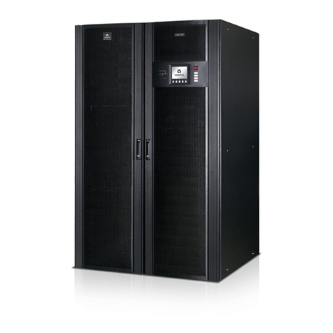
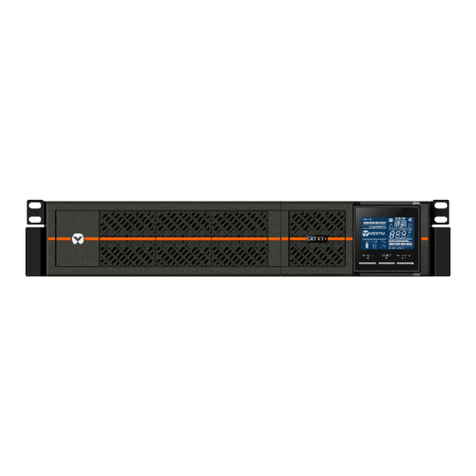
Vertiv Liebert GXTRT-1000IRT2UXL User manual

Vertiv

Vertiv Liebert GXTRT-1000IRT2UXL User manual

Vertiv Liebert GXT4 Series User manual

Vertiv

Vertiv Liebert GXT4 Series User manual

Vertiv Liebert GXT3 Series Installation and maintenance instructions

Vertiv

Vertiv Liebert GXT3 Series Installation and maintenance instructions

Vertiv Liebert GXT4-6000RTL630 Installation and maintenance instructions

Vertiv

Vertiv Liebert GXT4-6000RTL630 Installation and maintenance instructions

Vertiv Liebert EXS 30kVA User manual

Vertiv

Vertiv Liebert EXS 30kVA User manual

Vertiv Liebert EXM2 User manual

Vertiv

Vertiv Liebert EXM2 User manual

Vertiv Liebert GXT RT Series User manual

Vertiv

Vertiv Liebert GXT RT Series User manual

Vertiv Liebert EXM MBC User manual

Vertiv

Vertiv Liebert EXM MBC User manual

Vertiv Liebert EXS 0030kTH16FN01000 User manual

Vertiv

Vertiv Liebert EXS 0030kTH16FN01000 User manual

Vertiv Liebert GXT5 User manual

Vertiv

Vertiv Liebert GXT5 User manual

Vertiv NetSure 48 Series User manual

Vertiv

Vertiv NetSure 48 Series User manual

Vertiv Liebert PST5 Series User manual

Vertiv

Vertiv Liebert PST5 Series User manual

Vertiv Liebert NXC 0060kTJ1AFN02000 User manual

Vertiv

Vertiv Liebert NXC 0060kTJ1AFN02000 User manual

Vertiv Liebert PST4-660MT120 Installation and maintenance instructions

Vertiv

Vertiv Liebert PST4-660MT120 Installation and maintenance instructions

Vertiv Liebert APM 300 User manual

Vertiv

Vertiv Liebert APM 300 User manual

Vertiv Liebert EXS User manual

Vertiv

Vertiv Liebert EXS User manual

Vertiv Liebert GXT5-500LVRT2UXLN Installation and maintenance instructions

Vertiv

Vertiv Liebert GXT5-500LVRT2UXLN Installation and maintenance instructions

Vertiv Liebert EXS 10kVA User manual

Vertiv

Vertiv Liebert EXS 10kVA User manual

Vertiv Liebert EXL User manual

Vertiv

Vertiv Liebert EXL User manual

Vertiv Liebert EXM User manual

Vertiv

Vertiv Liebert EXM User manual
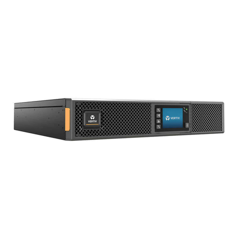
Vertiv Liebert GXT5-8000HVRT5UXLN User manual

Vertiv

Vertiv Liebert GXT5-8000HVRT5UXLN User manual

Vertiv Liebert GXT5 User manual

Vertiv

Vertiv Liebert GXT5 User manual

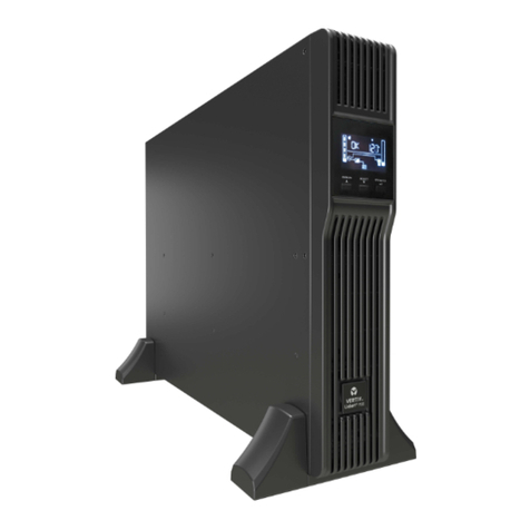
Vertiv PSA4-1000MT120 Installation and maintenance instructions
Vertiv

Vertiv PSA4-1000MT120 Installation and maintenance instructions
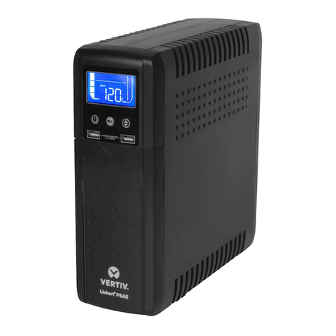
Vertiv LIEBERT GXT5-6000IRT5UXL User manual

Vertiv

Vertiv LIEBERT GXT5-6000IRT5UXL User manual

Popular UPS manuals by other brands

AEG Protect 3.M 2.0 manual

AEG

AEG Protect 3.M 2.0 manual

Alpha Novus FXM 650 Installation and operation manual

Alpha

Alpha Novus FXM 650 Installation and operation manual

CyberPower RB12120X2A user manual

CyberPower

CyberPower RB12120X2A user manual

Pylontech Victron & Pylontech US5000 manual

Pylontech

Pylontech Victron & Pylontech US5000 manual

BEL LDX-U20 user manual

BEL

BEL LDX-U20 user manual

Mustek PowerMust 530(B) Plus Startup manual

Mustek

Mustek PowerMust 530(B) Plus Startup manual

Emerson Liebert NXL series Operation and maintenance manual

Emerson

Emerson Liebert NXL series Operation and maintenance manual

MAKELSAN BOXER SERIES user manual

MAKELSAN

MAKELSAN BOXER SERIES user manual

Block PC-0524-400-0 manual

Block

Block PC-0524-400-0 manual

CyberPower CP585LCD user manual

CyberPower

CyberPower CP585LCD user manual

Eaton 3S Advanced user's guide

Eaton

Eaton 3S Advanced user's guide

CyberPower Office Tower Series UPS 1000 user manual

CyberPower

CyberPower Office Tower Series UPS 1000 user manual

CyberPower BM100 quick start guide

CyberPower

CyberPower BM100 quick start guide

Best Power 610 quick start guide

Best Power

Best Power 610 quick start guide

Best Power Unity/I UT3K user manual

Best Power

Best Power Unity/I UT3K user manual

Mustek PowerMust 400 Offline user manual

Mustek

Mustek PowerMust 400 Offline user manual

Xantrex Trace 512 UR-UPS owner's manual

Xantrex

Xantrex Trace 512 UR-UPS owner's manual

Forza SL-1501UL user manual

Forza

Forza SL-1501UL user manual

manuals.online logo
manuals.online logoBrands
  • About & Mission
  • Contact us
  • Privacy Policy
  • Terms and Conditions

Copyright 2025 Manuals.Online. All Rights Reserved.

590-1563-501A/SL-55016_REV1_3-17
1
LIEBERT® APS™
MODULE REPLACEMENT
Quick Installation Guide
These instructions apply to the
replacement or addition of the
following modules:
• Power module
• Battery module
• Charger module
• System control module
• System monitoring module
BATTERY, POWER, AND
CHARGER MODULE
REMOVAL
WARNING
:
Risk of heavy unit
falling over. Can cause equipment
damage, injury or death. Read all of the
instructions before attempting to move,
lift, remove packaging, or prepare the
unit for installation. The UPS represents
a tipping hazard.
Do not remove more than one module
at a time. Failure to do so may cause
unit to tip over and cause serious injury.
To locate a faulty module, remove the
bezel cover and look for an illuminated
yellow “fault” LED, which indicates a
faulty module.
If the removed bezel(s) have air filters,
replace them at this time.
NOTE
: If your system does not contain
a redundant module, place the UPS into
manual bypass mode before removing
modules to prevent accidental loss of
power to the connected equipment.
1. Removing the
module‑securing bracket
Use a Phillips-head screwdriver to
remove the fastener (if installed).
2. Releasing the lock lever
Pull out the lock lever slightly and
lift up, then wait a few seconds
before continuing.
3. Removing the module
from the cabinet bay
Slide the module out about
two-thirds of the way until it is
stopped by the safety catch.
Lift the module slightly and, while
supporting the module, slide it
completely out.
1
2
3
590-1563-501A/SL-55016_REV1_3-17
2
LIEBERT® APS™ MODULE REPLACEMENT
Quick Installation Guide
BATTERY, POWER, AND
CHARGER MODULE
INSTALLATION
4. Inserting a module
into a cabinet bay
Lift the module to the appropriate
bay, resting the end of the module
on the bay shelf.
NOTE
: Do not rest the module on
any plastic bezels. It could damage
the bezel.
NOTE
: Two battery modules must
be installed in the same row to
complete the battery string.
Slowly push the module in until
about one-third of the module is in
the bay.
Lift the module up, then continue
pushing until about 5 cm (2 in.) of
the module remains outside the bay,
then push it firmly and smoothly to
ensure that it is fully inserted.
5. Engaging the lock lever
Pull out the lock lever slightly
and press the lever down into the
bracket.
NOTE
: If the lever does not press
down smoothly, remove and reinstall
the module.
6. Attaching the
module‑securing bracket
Use a #2 Phillips-head screwdriver
to install the module-securing
bracket.
7. Replace the plastic bezel(s).
4
5
4
590-1563-501A/SL-55016_REV1_3-17
3
LIEBERT® APS™ MODULE REPLACEMENT
Quick Installation Guide
SYSTEM CONTROL OR
SYSTEM MONITORING
MODULE REMOVAL
CAUTION
:
When both a control
and monitoring module need replaced,
do not remove them at the same time.
If both are removed, the UPS shuts
down and power is removed from
the connected equipment unless
the system includes an external
maintenance-bypass system, and the
UPS is operating in maintenance-
bypass mode.
1. Remove the display bezel
and the LCD display.
Lay the display module on top
of the UPS.
2. Freeing the module
Use a Phillips-head screwdriver
to remove the screws from the
2 securing holes.
3. Releasing the lock lever
Pull out the lock lever slightly
and pull to the left, then wait a few
seconds before continuing.
4. Removing the module
Being sure to support the module,
slide it completely out of its control
bay.
NOTE
: These modules do not have
a safety catch because they are
lightweight.
SYSTEM CONTROL OR
SYSTEM MONITORING
MODULE INSTALLATION
5. Inserting a module
into a control bay
Push the module in until about 1
cm (1/2 in.) of the module remains
outside the bay, then push it firmly
and smoothly to ensure that it is
fully inserted.
6. Engaging the lock lever
Pull out the lock lever slightly and
press the lever to the right into
the bracket.
7. Re‑attaching the module
to the cabinet
Use a #2 Phillips-head screwdriver
to resecure the module.
8. Replace the LCD display
and the display bezel.
1
2
3
4
5
4
6
VertivCo.com |Vertiv Headquarters, 1050 Dearborn Drive, Columbus, OH, 43085, USA
© 2017 Vertiv Co. All rights reserved. Vertiv and the Vertiv logo are trademarks or registered trademarks of Vertiv Co. All other names and logos referred to are trade names, trademarks or
registered trademarks of their respective owners. While every precaution has been taken to ensure accuracy and completeness herein, Vertiv Co. assumes no responsibility, and disclaims all
liability, for damages resulting from use of this information or for any errors or omissions. Specications are subject to change without notice.
590-1563-501A/SL-55016_REV1_3-17
4