VEXILAR FL-8SLT User manual

1
CONTENTS
General Description 2
Specifications 3
Unit Installation 4
Power Connection 4
Transducer Installation 5 - 8
Operation - 10
Typical Indications 11 - 14
Maintenance 15
Operational Questions & Answers 16 - 20
Transducer Beam Angle Chart 21
Trouble Shooting Chart 22
Accessories and Other Products 23 - 25
Transducers 26 - 27
Service and Support 28
Founded in 1 60, Vexilar, Inc. has a long his-
tory of bringing revolutionary technology to the
sport fishing industry. Just some of the Vexilar
firsts include: the first liquid crystal display, the
first fish alarm, the first three color display, and
the first CRT and straight line paper graphs, for
the sport fisherman. Now, with the FL-8SLT, we bring you the first true
interference Rejection unit. Again, Vexilar leads, while the others follow.
FL-8SLT Operation Manual

2
GENERAL DESCRIPTION
The FL-8SLT is a compact
and lightweight depth
sounder designed for serious
anglers. Besides indicating
depth, the unit also shows
changes in bottom content and
conditions. It can also dis-
criminate between large
underwater targets, such as
fish, and smaller targets such
as bait fish and plankton.
The unit transmits bursts
of high frequency pulses,
which are converted from
electrical to mechanical energy by the transducer. These "sound" pulses
radiate from the transducer downward and are reflected back up to the
transducer where the energy is converted back to electrical signals. The
FL-8SLT then processes these signals and displays them.
The circular display is accomplished by attaching an LED (Light
Emitting Diode) to a wheel, which is then spun at a high speed in the
clockwise direction. This allows for an extremely high speed update.
The bottom, as well as other targets, can be displayed as red, orange, or
green to indicate strong, medium and weak signals respectively. The FL-
8SLT also has patented Interference Rejection (IR) Technology. This lets
the user "filter out" unwanted interference from another nearby depth
sounder. With two models available, deep and shallow, and a wide vari-
ety of accessories to choose from, the Vexilar FL-8SLT is second to none.

3
SPECIFICATIONS
Operating Voltage: 10.5 - 15 Volts (12 Volts Nominal)
Current Draw: 200mA
Power Output: 400 Watts (Peak to Peak)
Frequency: 200 kHz
Resolution: 525 Segments
Target Separation: 2.65" Min.
Display Colors: 3 - Red, Orange, and Green
Dimensions: 4.4"H x 6"W x 2.5"D
Weight: 1.1 Lbs.
Dept Scales:
0-20', 0-30', 0-40', 0-60', 0-80', and 0-120' - Shallow Model
Or
0-20', 0-30', 0-40', 0-60', 0-80', and 0-240' - Deep Model
Beam Angle:
If your transducer is not marked, you can determine the beam angle
by the dimensions of the transducer face. Measure the shortest distance
across the face of the transducer. 1 ˚ transducers measure about 1 1/2”.
º and dual beam transducers will be about 2 1/2” across the face.

4
INSTALLATION
To make the FL-8SLT work, you must provide the unit with power
and mount the transducer in an appropriate location.
UNIT INSTALLATION
Find a convenient place to
mount the unit. This may include
a boat seat, deck, dash, or a
portable case. Make sure that there
is plenty of room for the unit to tilt
and/or swivel freely without the
cables binding behind the unit.
Once you have found a spot,
remove the unit from the gimbal
bracket. Securely attach the brack-
et to the mounting surface.
POWER CONNECTION
Plug the flat 3 pin connector into the back of the unit. Find the clos-
est source of 12 volts and run the cord to it. Keep the cord away from
sharp metal edges and avoid tight places where the cord may get crushed.
Connect the red wire to positive and the black wire to negative or ground.
If the cord provided is not long enough, more can be added. Use 18 gauge
wire minimum. It is recommended that a 1 amp in-line fuse be placed
in the positive line as close to the power source as possible to protect
against any shorts in the wiring.

5
TRANSDUCER INSTALLATION
There are three basic types of transducers to consider: High Speed,
Puck Style, and the Ice-Ducer System.
HIGH SPEED TRANSDUCERS
High Speed transducers are
designed to be mounted on the transom
of a boat. The wedged shape will cut
the water and give a clear depth read-
ing at any boat speed. Locate a spot
similar to the one in figure E. Keep in
mind that you need clear water flow
across the face of the transducer to
insure a clear reading at all speeds. Stay
away from rivets, ribs, or strakes that
would be just in front of the transduc-
er. They will disturb the water and
scramble the reading. Attach the
mounting bracket to the transducer and
hold it up to the boat where you are
planning to mount it (see figure E).
Mark the holes on the transom, or mounting plate, so that when the bot-
tom of the transducer is flush with the bottom of the boat the holes are
located at the bottom of the bracket slots. This gives you room to "fine
tune" the position of the transducer and optimize your reading after
you've put the back boat in the water. Drill out the holes and tighten the
bracket down securely. Be sure to seal any holes drilled
into the transom with silicone to prevent water from leak-
ing into the boat. Run the transducer cord up to the unit
taking the same care as you did when you ran the power
cord. Plug the transducer connector into the back of the
unit and screw the retaining ring down tight.
Figure E

6
PUCK STYLE TRANSDUCERS
There are three ways in which a Puck Style trans-
ducer can be mounted. It can be mounted In-Hull, on
an electric trolling motor, or portable (with a suction
cup or on an arm of some type).
IN-HULL MOUNTING
This method, gluing the transducer to the hull, gets the same results
as if you were using the High Speed transducer only there are no holes
to drill in the boat and there is no transducer on the transom to get dam-
aged by impact.
Finding the best location for the transducer before mounting is crit-
ical. Choose a flat smooth spot near the center of the bilge and near the
back of the boat. It is a good idea to make a "test run" before you per-
manently install the transducer to make sure that you can indeed get a
reading through your hull, and when the boat is on plane. Put about a
half inch of water in the bilge and hold the transducer in the intended
location. Move the transducer around until you get the best reading.
Mark the spot.
To install the transducer clean the spot of mud and oil. Using an
epoxy or silicone glue make a puddle about the same diameter as the
transducer on the hull. Place the transducer in the glue. Press it down
firmly, gently twisting it back and forth, making sure that there are no
air bubbles in the glue between the transducer and the hull. Let the glue
dry completely before turning the unit on.
Run the transducer cord up to the unit taking the same care as you
did when you ran the power cord. Plug the transducer connector into
the back of the unit and screw the retaining ring down tight.

7
TROLLING MOTOR MOUNTING
To attach a Puck Style transducer to a trolling
motor, use a hose clamp or a large cable tie. Notice the
slots in the transducer for this purpose. Locate the
transducer on the bottom of the lower unit as in figure
G. Run the cable up the shaft using cable ties to hold
it in position. Make sure that the movement of the
trolling motor will not damage the cable. Plug the transducer connector
into the back of the unit and screw the retaining ring down tight.
PORTABLE MOUNTING
Optional suction cup brackets can be used to temporarily attach a
transducer to the transom or side of the boat. The cups should be placed
in a location where it will not be torn off when the boat goes high speed.
It is a good idea to tie on a safety rope in case the cup does let go.
There are three suction cup brackets available for the FL-8SLT. The
BK0023 and BK0027 are made to attach the Puck style transducers to a
boat for use at slow speeds. The BK0044 suction cup brackets is made to
attach the high speed transducers to a boat for high speed uses. See page
26 for details.
An arm can also be used to hold the transducer. Simply attach the
transducer to the end of the arm using cable ties or tape. If the arm is
constructed of metal tubing insulate the transducer from the arm by wrap-
ping electrical tape around the arm. This prevents "ringing" which can
be displayed as noise near the surface.
Run the transducer cord up to the unit using cable ties to hold the
cord in place. Plug the transducer connector into the back of the unit and
screw the retaining ring down tight.
Figure G

8
THE ICE-DUCER™ SYSTEM*
The Ice-Ducer system provides a quick and easy way to set up the
transducer for ice fishing. All of the adjustments needed to find the true
perpendicular point are done automatically. To use the Ice-Ducer, sim-
ply adjust the transducer to the desired depth and drop the assembly in
the ice hole.
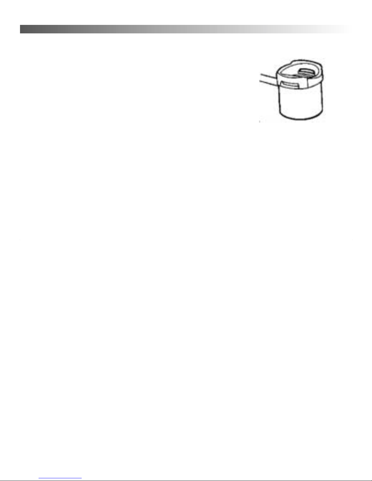
There are three main com-
ponents to the Ice-Ducer system.
They include the transducer,
float, and the stop. The trans-
ducer comes assembled with the
connector already installed. The
stop is put on by passing the
transducer cord through the slit
in the side of the stop. Make
sure that the tapered or round-
ed end is facing down, toward
the transducer. The float is
installed between the stop and
the transducer by, again, passing the transducer cord through the slit in
the side. Make sure the countersunk hole is facing up towards the top.
To use the Ice-Ducer, adjust the stop to allow the transducer to float
at the desired depth. A six inch minimum is recommended in order to
make sure that the transducer will indeed be pointing straight down.
The most it should be down is to the bottom of the ice hole. If the trans-
ducer is below the bottom of the ice it can cause tangling problems when
bringing in fish.
If you run into problems when using the Ice-Ducer and you can't see
your bait try this, rub the bottom of the transducer with water to elimi-
nate any residue or air film. This insures good contact between the trans-
ducer and the water. Check the length of cord between the float and the
transducer to make sure there are no kinks in the cord that will cause the
transducer to shoot off to the side
*Patent no. 5,546,362

9
OPERATION
Figure I shows the three main controls of the FL-8SLT.
They include Power and Range control, Gain, and
Interference Rejection.
POWER AND RANGE CONTROL
The knob located at the bottom of the control panel
turns the unit on and selects which range is to be used.
The center position is the Off position. There are six depth
ranges to choose from.
S1 - 0-20' D1 - 0-30'
S2 - 0-40' D2 - 0-60'
S4 - 0-80' D4 - 0-120'
(D8 - 0-240' Deep Model)
To activate the unit and select the appropriate range turn the knob
to the left or right. To read the correct depth on the display you must
correlate your range setting with the proper scale on the display. Notice
that the shallow ranges are marked in white and the deep ranges are
marked in yellow. For a range selection of S1 you would read the white
numbers on the display. For a range selection of S2 you would read the
white numbers times two, and times four for S4. The same is the case for
the D ranges, only you would read the yellow numbers on the display.
For example, figure J shows the leading edge of the bottom at nine
feet on the white scale. With a range setting of S1 you would interpret
this as nine feet deep. With a range setting of S2 you would interpret this
as 18 feet deep. With a range setting of D1 you would look at the yellow
numbers and read the depth as slightly over 13 feet deep. D2 would read
26 feet. A setting of D4 would read the depth at 52 feet (13 x 4).
Figure I

10
GAIN CONTROL
The knob located at the top of the control panel is the gain control.
This controls the amount of signal that you see on the display. A gain
setting of zero will display a minimum amount of signal while a gain set-
ting of ten will show the maximum amount. Different conditions will
require different gain settings. Deeper water will require higher gain
than shallow water. A weedy bottom will demand a lower gain setting
than a clean bottom. Keep the gain level low. Too much gain can "wash
out" the targets that you want to see. Generally, it is a good idea to set
the gain at an appropriate level and leave it there. Only change the gain
level if the water depth or conditions change.
INTERFERENCE REJECTION*
The yellow button in the middle of the panel controls the Interference
Rejection feature. The red LED to the upper left of the I.R. button tells
you if the rejection circuitry is on. The I.R. feature has eight steps of rejec-
tion to let you eliminate unwanted interference from another nearby
depth finder. When you turn on the FL-8SLT on, the I.R. automatically
comes on to the first step. If necessary, press the I.R. button repeatedly
until the interference is eliminated. You can press the button seven times
before you get back to the first step again. Turning the unit off and then
on again will also reset the I.R. back to the first step. To turn the I.R. fea-
ture off press the Gain control knob. The red LED will also go off.
TIP - If running two SLTs, it is best to turn the I.R. off on one unit
and then eliminate the interference on the other unit.
* Patent #5,515,33

11
TYPICAL INDICATIONS
The three-color display on the FL-8SLT can give you a lot of infor-
mation if you know how to read it. A color represents the strength of a
signal. A red color indicates a strong signal, an orange color indicated a
medium strength signal, and green represents a weak signal. The colors
will combine to indicate objects, such as bottom echoes, structure, fish,
and plankton. The way in which they combine, and the speed in which
they do so, tells you what is what.
The following examples illustrate some of the different conditions
that you may encounter and what the display on the FL-8SLT may look
like.
HARD BOTTOM
Under these conditions the bottom will be almost all red, although
you will always see some orange and green at the trailing edge, as in fig-
ure J. A sharp red leading edge tells you that the bottom is very clean. If
you were to move from a hard bottom to a softer -bottom you would see
a change in color to more orange and green. Try not to change the Gain
setting as you move around.
WEEDY BOTTOM
In weedy conditions the bottom can be harder to determine. Figure
K gives you an idea of what it may look like. To find the bottom in weeds
it is important to keep the gain control low. If the gain is too high the
bottom and the weeds will "run together" making it difficult to determine
the actual depth. Some weed beds can be so dense that they will display
as solid red, even at medium gain. If you fish in these conditions often
you may want to add an S-Cable to your system (see page 27).

12
Fig. J
Fig. K
ZERO MARK
ZERO MARK
2ND ECHO
TRAILING
EDGE
TRAILING
EDGE
BOTTOM
BOTTOM
SURFACE
CLUTTER
SURFACE
CLUTTER
BAIT FISH
OR
PLANKTON
FISH
LEADING EDGE
LEADING EDGE
POSSIBLE FISH
WEEDS

13
SEEING FISH
The FL-8SLT sees a fish as a target, much like the bottom. It has a
leading edge, a width, and color content. Refer, again, to figure J. If the
range setting is S x2 then the fish is just over two feet above the bottom.
It is a fairly wide target and is made up of all three colors. This should
be recognized as a significant fish, something you may want to catch.
The targets that appear just above this fish are smaller and there is no
red. Here is where target identification gets a bit trickier. Since we do not
know the position of the targets in the cone of sound we cannot readily
identify them. For example, the green target at ten feet could be a small
piece of floating debris or a single small baitfish in the center of the cone
or it could be a large game fish at the very edge of the cone.
In the weeds spotting fish is more difficult. Figure K shows a bot-
tom at twelve feet (S1). The weeds extend from the bottom up to about
eight feet. Notice the red target at ten feet is marked "possible fish". We
cannot say that it is a definite fish because the weeds around it are dense
enough to give a red signal themselves. Again, keep the gain as low as
you can for reading in the weeds. If you can't turn the gain down far
enough you may want to get an S-Cable to cut down the power of your
unit.
CLUTTER VS. NOISE
Clutter is created by very small targets in the water. It is usually dis-
played as thin green or orange lines. Clutter can include bait fish, plank-
ton, floating debris, or air bubbles. Although clutter is not fish, it can be
useful in finding fish.
Noise is, usually, electrical noise, which is in the engine ignition,
radios, or trolling motors. It can be displayed as red, orange, or green
lights that flash as the interfering equipment is operated. The Interference
Reject circuit of the FL-8SLT will block out most noise, but sometimes,
extra measures are required to eliminate it. Please contact our service
department (page 28) if you have interference that you cannot get rid of.

14
HIGH SPEED OPERATION
The FL-8SLT can accurately read depths at almost any boat speed.
Here high speed is defined as any speed at or above the planning speed
of the boat. Once the boat starts to plane out, turbulence will develop
behind the transom. If you have the wrong type of transducer, or it is
poorly mounted, the unit will lose the bottom at a certain boat speed.
This is due to all of the air bubbles in the turbulent water.
ICE FISHING
Ice fishing brings out the best in the FL-8SLT. The stable platform of
ice lets you concentrate on your bait and the fish around it. The bottom
becomes less important because it never changes. The only movement
on the display is of your bait and fish.
Unlike open water use, the direction in which the transducer is point-
ed is very critical. You want your bait to be located in the dead center of
the cone sound. This way you can see very small baits at low gain set-
tings and also see fish come in from all sides. If you are not using the Ice-
Ducer system, the transducer must be attached to an adjustable arm so
that it can be manually pointed directly at the bait. Sometimes it helps
to attach a bubble level to the transducer so that you know when it's
straight.
After your system is properly set up, adjust the gain until you see
your bait as a green target. You may need to readjust the gain control to
keep the bait green. This is due to the changing condition and position
of your bait. If you are using a swimming bait or a lure that darts to the
side as it's jigged, you will see the color change as the bait moves.
Sometimes it may even disappear if the bait goes out of the cone of sound.
Fish will appear at the edge of the cone as a green target. If the fish
moves closer to the bait it will change from green to orange. If it moves
up, right next to the bait, it will change to red. If the fish leaves and you
can no longer see your bait, chances are, you've been robbed.

15
MAINTENANCE
PERMANENT MOUNT
With permanent mount applications, the power cord is left connect-
ed to the source, the transducer is not easily removed, and the gimbal
bracket is screwed to the seat, deck, or dash. Under these conditions
maintenance is very simple because nothing changes once the unit is
installed. Because of this problems can sneak up on you if you're not
careful.
The unit should be removed from the bracket whenever the boat is
parked to guard against theft. Don't store it in a place that may fill with
water.
Power connections need constant checking. Corrosion can develop
and cause intermittent or loss of operation. Connections made to battery
posts need extra attention because of the battery acid.
The transducer should be checked for scratches and cracks which
can reduce the unit’s sensitivity. Cuts or breaks in the cord should be
repaired as soon as possible so corrosion doesn't attack the wire.
Periodically clean the face of the transducer with a mild detergent. An
oily film can develop which will cause weak readings.
PORTABLE MAINTENANCE
In portable applications the unit is generally mounted to a carrying
case and the transducer is frequently removed, as is the power. These
conditions can cause more wear and tear than a permanently mounted
unit.
In addition to the previously mentioned maintenance items, be sure
to check for broken or pulled wires, loose screws or hardware, and, above
all, battery condition.

16
OPERATIONAL QUESTIONS & ANSWERS
W ere S ould T e Gain Control Be Set?
For ice fis ing - the gain control should be set so the bait you are
fishing with is shown in green color on the dial. This color should be set
while the lure or bait is at the normal fishing depth. As the bait is raised
toward the surface the colors will turn to orange and possibly red, just
below the surface. This happens because as the bait is raised towards the
surface the signal strength from the bait gets stronger, resulting in color
change.
For open water fis ing - set the gain control so as to get a strong bot-
tom echo along with a second echo. You may need to switch to a deep-
er range to see the second echo. The leading edge of the bottom echo will
show a solid Red band, then bleeding into the orange color, then the trail-
ing edge of the bottom will bleed from orange into the green color. Good
bottom echoes, most of the time, will show all three colors, starting with
Red, Orange, into Green.
W y Can't I See My Bait W ile Ice Fis ing, or like I can
w ile ice fis ing?
For Ice Fis ing - In order to see your bait it must be in the center of
the cone and you must have your gain turned up high enough to see it.
For open water - With the position of the transducer mounted to the
boat, it is hard to get your bait there, and with the motion of the water it
makes it difficult to keep it there. If all conditions are right you will be
able to see your bait.
W y Do Some Lures S ow Up Better T an Ot ers?
The amount of Reflective Surface Area on the lure is the main rea-
son. A thin vertical lure is not as easy to see as a horizontal fat lure.

17
W at Color S ould Fis Be?
For ice fis ing - with the FL-8SLT being operated with the perpen-
dicular position found, the fish target entering the outside of the cone of
sound will appear in green, as it moves towards the bait it will add some
orange into the center of the signal, and if the fish continues to the per-
pendicular line under the transducer, red will be added to the center of
the fish target. These color changes will take place automatically with-
out adjusting the gain control. This color change feature allows the oper-
ator to observe the fish moving towards or away from your bait.
For Open Water - The fish can appear the same way on open water
as they do ice fishing. The same rules apply. Although, instead of the
nice stable platform of ice you have wave and boat motion to contend
with. Usually the boat moves more than the fish. If you see a red target
separated from the bottom you can bet that it's a fish. If all you see is
green or orange you won't know if it's a fish until it turns red
How Long Will My Battery Last On T e FL-8SLT?
Run Time - The FL-8SLT draws about 200 mA, less than a quarter of
an amp of current The unit will run good until the battery voltage drops
to about 10 volts. Beyond that you will notice lower sensitivity, as well
as, a much dimmer display. The Vexilar Model V120, a 7.2 amp/hr bat-
tery, will run the FL-8SLT for about 20 hours straight.
Battery Life - This applies only to rechargeable batteries. The largest
influence on battery life is your charging habits. To get the most out of
your battery follow these simple tips; Charge the battery as soon as pos-
sible after each use or, if it's cold, as soon as it reaches room temperature.
Do not overcharge or under charge the battery. Use a battery charger
that has an automatic shut-off feature. A battery should be stored, fully
charged, in a cool place. Charge it once a month or so when in storage
to make sure it's full.

18
How Far Down T e Ice Hole Does T e Ice-Ducer Have
To Be?
You need water contact only to get a depth reading. The bottom or
the face of the transducer, only, has to make contact with the water in
order to get a good transfer of sound waves into the water
There are times (usually deep ice - 36" or more) when the transduc-
er needs to be placed at the bottom of the ice. The zero indication of the
flasher will be unusually wide, 8 to 10 feet wide. This can be caused by
the transmitted signal ringing back and forth through the depth of the
hole. By extending the transducer to the bottom of the hole this ringing
can be eliminated. Now the lake depth must be mentally corrected for
the new position of the transducer.
Will T e FL-8SLT Read T roug T e Ice?
YES! It will easily read through ice, provided the ice is CLEAR ICE
and not MILKY ICE. Remember, the transducer must have GOOD CON-
TACT with the surface of the clear ice. A bottom indication should appear
on the sounders dial at an appropriate depth. The ice surface must be
wet; water works well.
W y Do I Get Interference?
Electrical interference can be caused by other electrical equipment
that put unwanted signals on the power line. It usually can be reduced
or eliminated by simple fixes such as resistor spark plugs and wires on
the engine or better grounding on the electrical system. Sometimes, how-
ever, there can be equipment problems that need shop service.
Another kind of interference comes from another depth finder oper-
ating on the same frequency nearby. The FL-8SLTs interference rejection
circuitry is designed to knock out most or all of this, but sometimes severe
conditions can still cause interference. The two factors that determine if
this happens are: a) the depth of the water and, b) how far apart the two

19
sounders are placed. If this interference is happening, each of the sounders
will have a non-stop rotating light moving around the dial. One mov-
ing light rotates around the dial clockwise and on the other sounder the
light will rotate in the counter clockwise direction. To eliminate this prob-
lem you can either move the sounders farther apart or shut one off.
W ic Side of t e Transducer S ould Be Aimed Toward
T e Lake Bottom?
Most of today's transducers have two sides to them. Side A is the
side that the cable enters the transducer and usually has holes, slots, or
some method to attach a bracket to. Side B is usually flat but may have
different shapes, such as round, square, or arrow shaped. The Side B or
the Flat side should be aimed toward the lake bottom.
W at Does t e Zero Lig t Mean?
The zero light is actually the start point of the units transmission of
sound waves. On the display it indicates the zero foot point. This sig-
nal has very little use. Sometimes a portable transducer arm can cause
"ringing" which will display as a very wide zero. The width of the zero
indication should never be more than 5 feet wide. Most problems
occur when the arm, which the transducer is attached to, is metal.
Plastic or wood transducer arms cause little problems. To test your
portable box system, in air, turn the FL-8SLT on, range 1, and with the
gain control turned to maximum position, note the width of the zero
indication. If the zero indication is wider than 5 feet, squeeze the
transducer and metal arm together with your hand. While squeezing,
if the zero gets smaller you need to work on the transducer attach-
ment. To solve the problem, especially with a metal transducer arm,
remove the transducer from the metal arm. Then tape three layers of
black electrical tape around the arm in the flat section of the arm, then
lay the transducer against the tape and continue to tape it onto the flat
section on the metal arm. The tape creates an insulation layer between

20
the metal arm and the plastic housing of the transducer. This insula-
tion layer eliminates any transmission vibrations caused when the unit
transmits the signal to the water.
W at Does t e Bottom Lig t Mean?
Besides depth the bottom light can give you a lot of information. The
width and color content of the bottom signal can tell you what type of
bottom it is.
Ice fisherman can look for movement of color in the bottom signal.
If you see a red line move through the orange or green part of the bot-
tom signal, it's probably a fish close to the bottom and away from the
center point.
Open water fisherman usually can't see this because the boat moves
too much. You can, however, see changes in the bottom type as you move
along. The more red in the signal, the harder the bottom. The more green
and orange in the softer the bottom
W y is t e Bottom Indication so Wide?
While fishing in a depth of 30 feet, a normal width of a bottom indi-
cation is from 5 to 12 feet wide. The width of the bottom is actually the
summation of the radius of coverage on the bottom and is controlled by
the gain control. The bottom width and color adjust automatically. The
leading edge of the bottom light is the actual depth. The color beyond is
the area, within the cone of sound, which is around the center point of
the circle you are covering on the bottom.
Other manuals for FL-8SLT
1
Table of contents
Other VEXILAR Marine Equipment manuals

VEXILAR
VEXILAR LC-8 User manual

VEXILAR
VEXILAR FL-8 User manual

VEXILAR
VEXILAR FL-8SE User manual

VEXILAR
VEXILAR EDGE LC-507 User manual

VEXILAR
VEXILAR FL-8SE User manual

VEXILAR
VEXILAR FL-18 User manual

VEXILAR
VEXILAR EDGE 3 User manual

VEXILAR
VEXILAR Boundary Waters LC-10 User manual

VEXILAR
VEXILAR CLC-200 User manual

VEXILAR
VEXILAR CLC-200 User manual
Popular Marine Equipment manuals by other brands

New Age
New Age PRM Delta Workshop manual

Reflex Marine
Reflex Marine FROG XT10 user manual

Simrad
Simrad GC80 EXPANDED instruction manual

Clarion
Clarion CMS3 Owner's manual & installation manual

Teleflex Marine
Teleflex Marine BayStar installation manual

olympia electronics
olympia electronics BS-531 quick start guide