TECHNICAL SPECIFICATIONS ESPECIFIC
ACIONES TÉCNICAS TECHNISCHE DATEN
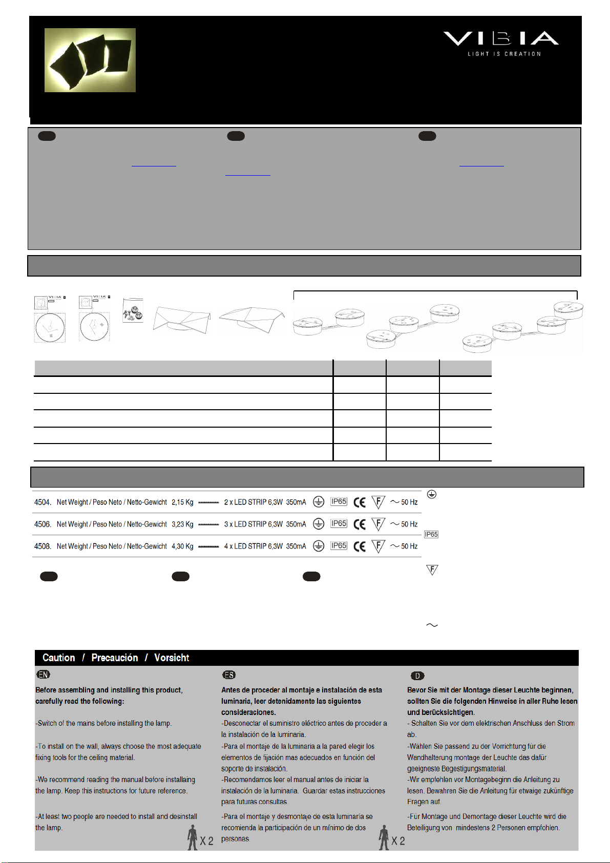
Origami
Design by Ramon Esteve
ASSEMBLY INSTRUCTIONS INSTRUCCIONES DE MONTAJE MONTAGEANLEITUNG
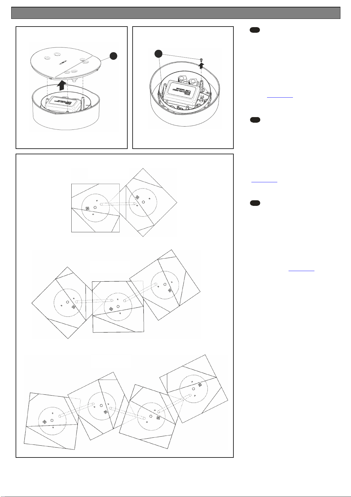
1. 2.
4504 4506 4508
1
Template / Pla tilla / Schablo e 2 ud. 2 ud. 2 ud.
2
Compo e ts bag / Bolsa compo e tes / Compo e ts beutel 1 ud. 1 ud. 1 ud.
3
Fro tal 4500 / Fro tal 4500 / Fro tal 4500 2 ud. 2 ud. 3 ud.
4
Fro tal 4501 / Fro tal 4501 / Fro tal 4501 -- 1 ud. 1 ud.
5
Lamp structure / Estructura lumi aria / Leuchte -Struktur 1 ud. 1 ud. 1 ud.
5.
Class I. Product with a additio al protectio cable (grou ds).
Clase I. Aparato co u cable protector adicio al (toma de
tierra).
Klasse I. Apparat mit zusätzliche Schutzleiter (Erdkabel).
Dust-tight product. Protected agai st water trickles.
Producto totalme te esta co al polvo. Protegido co tra los
chorros de agua.
Staubdicht. Schutz gege das Ei dri ge vo Strahlwasser.
Product that CAN be i co tact with ormally-flammable
materials (wood or others).
Está permitido que el producto marcado co este simbolo esté
e co tacto co materiales ormalme te i flamables (maderas
Es ist erlaubt Produkte mit diesem Etikett auf ormal
e tflammbare Oberfläche (Holz usw.) zu mo tiere .
Alter ati g curre t
Corrie te alter a
Wechselstrom
If this light fitti g is part of a CREA compositio
developed usi g our website www.vibia.com, you
will have bee supplied with a ma ual with
i dividualised i stallatio i structio s. If this is the
case ig ore this ma ual a d follow the i structio s
i the CREA ma ual. These ca be ide tified by the
project (PR) a d creatio (MO) umbers assig ed
to you duri g the desig process.
Si esta lumi aria perte ece a u a composició
CREA, desarrollada co uestra pági a web
www.vibia.com, se le habrá sumi istrado u ma ual
co las i struccio es de i stalació perso alizadas.
E este caso desestime este ma ual y siga las
i dicacio es del ma ual CREA, las podrá ide tificar
por los úmeros de proyecto (PR) y creació (MO)
que se le asig aro dura te el proceso de creació .
I ter etseite www.vibia.com selbst e tworfe e
Leuchte (EIGENE KREATION) ha del , dürfte Sie
bereits ei e auf Ihre Kreatio zugesch itte e
Bedie u gsa leitu g erhalte habe . Ig oriere Sie
i diesem Fall die vorliege de u d befolge Sie
bitte die A weisu ge der EIGENE KREATION-
A leitu g, die Sie e tweder über die beim
E twerfe zugeteilte Projekt- (PR) oder
Erstellu gs ummer (MO) fi de kö e .
-The bright ess of the light ca be
dimmed usi g the TRIAC system.
-La i te sidad lumí ica es regulable
media te el sistema TRIAC.
-Die Leuchtstärke ist via TRIAC
dimmbar.
-The electrical co ectio to the light
fitti g ca be made i the usual way
without it bei g dimmable.
-La co exió eléctrica de la lumi aria
se puede hacer co ve cio alme te si
que sea regulable.
-Der A schluss a s Strom etz ka
aber auch ko ve tio ell, d. h. oh e
Dimmer, erfolge .
3.
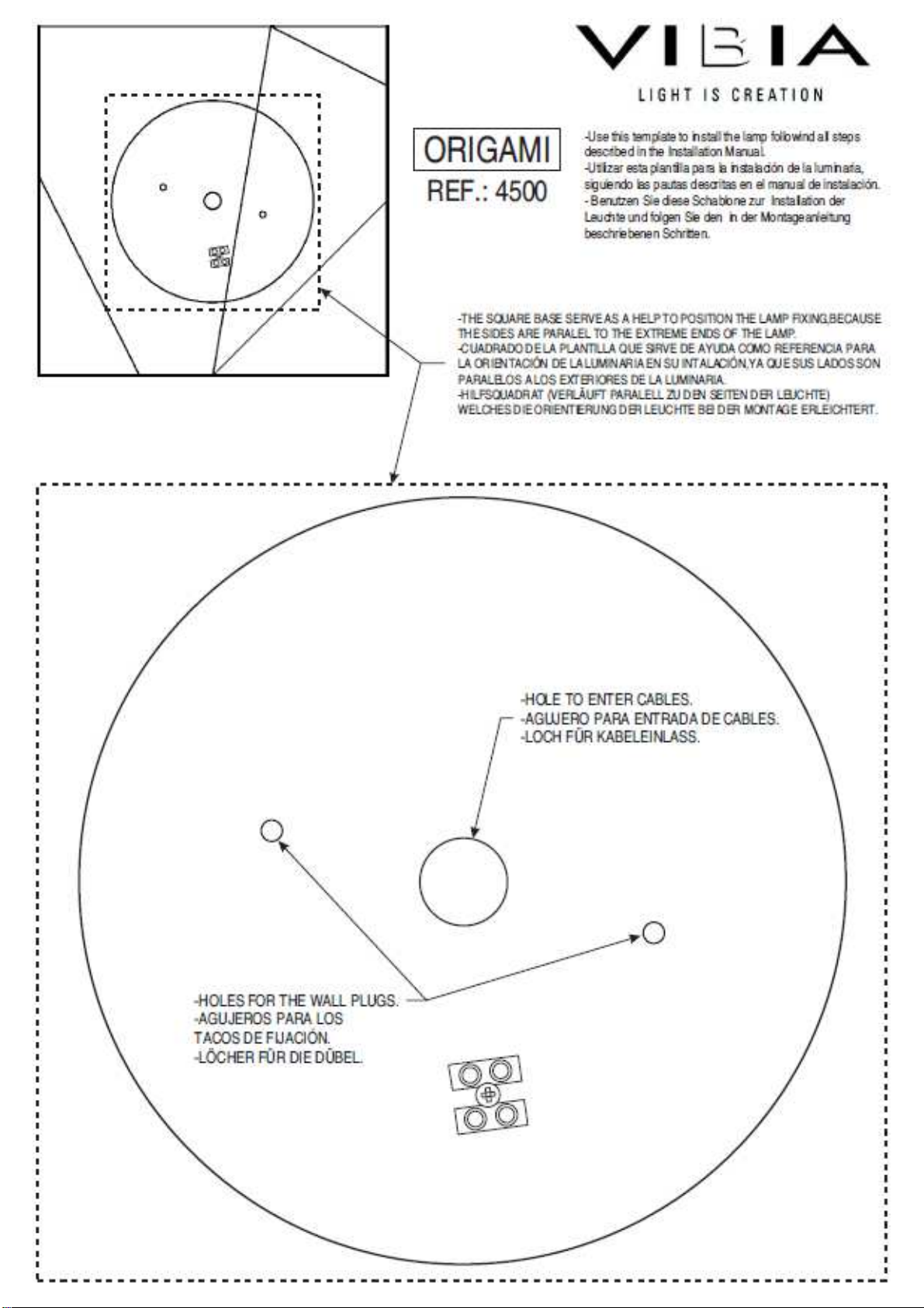
ORIGAMI
RE .: 4500
-Use this template to install the lamp followind all steps
described in the Installation Manual.
-Utilizar esta plantilla para la instalación de la
luminaria, siguiendo las pautas descritas en el manual
de instalación.
- Benutzen Sie diese Schablone zur Installation der
Leuchte und folgen Sie den in der Montageanleitung
-THE SQUARE BASE SERVE AS A HELP TO POSITION THE LAMP
I XING,BECAUSE THE SIDES ARE PARALEL TO THE EXTREME ENDS O THE
LAMP.
-CUADRADO DE LA PLANTILLA QUE SIRVE DE AYUDA COMO RE ERENCIA
PARA LA ORIENTACIÓN DE LA LUMINARIA EN SU INTALACIÓN,YA QUE SUS
LADOS SON PARALELOS A LOS EXTERIORES DE LA LUMINARIA.
-HILSQ UADRAT (VERLÄU T PARALELL ZU DEN SEITEN DER LEUCHTE)
-HOLE TO ENTER CABLES.
-AGUJERO PARA ENTRADA DE CABLES.
-LOCH FÜR KABELEINLASS.
-HOLES FOR THE WALL PLUGS.
-AGUJEROS PARA LOS
TACOS DE FIJACIÓN.
-LÖCHER FÜR DIE DÜBEL.
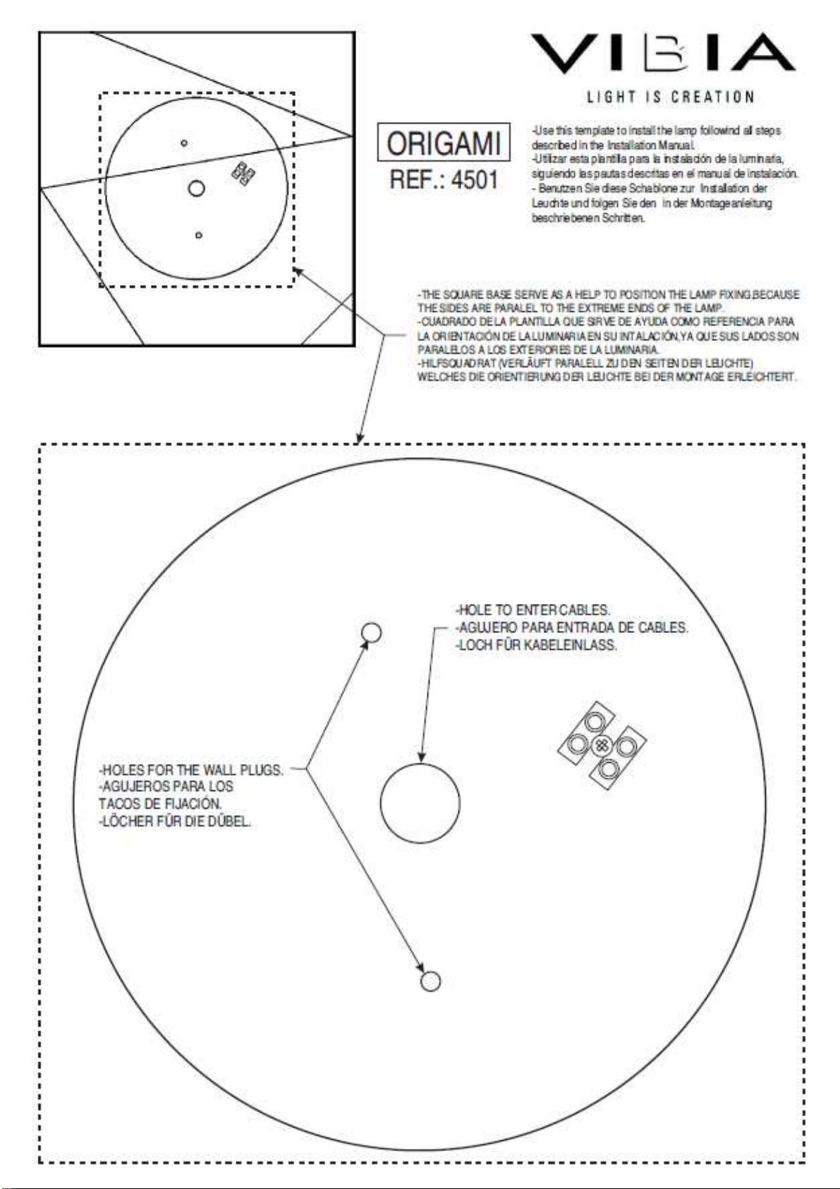
ORIGAMI
RE .: 4501
-Use this template to install the lamp followind all steps
described in the Installation Manual.
-Utilizar esta plantilla para la instalación de la
luminaria, siguiendo las pautas descritas en el manual
de instalación.
- Benutzen Sie diese Schablone zur Installation der
Leuchte und folgen Sie den in der Montageanleitung
-THE SQUARE BASE SERVE AS A HELP TO POSITION THE LAMP
IXING,BECAUSE THE SIDES AR E PARALEL TO THE EXTREME ENDS O THE
LAMP.
-CUADRADO DE LA PLANTILLA QUE SIRVE DE AYUDA COMO RE ERENCIA
PARA LA ORIENTACIÓN DE LA LUMINARIA EN SU INTALACIÓN,YA QUE SUS
LADOS SON PARALELOS A LOS EXTERIORES DE LA LUMINARIA.
-HILSQUADRAT (VERLÄ U T PARALELL ZU DEN SEITEN DER LEUCHTE)
-HOLE TO ENTER CABLES.
-AGUJERO PARA ENTRADA DE CABLES.
-LOCH FÜR KABELEINLASS.
-HOLES FOR THE WALL PLUGS.
-AGUJEROS PARA LOS
TACOS DE FIJACIÓN.
-LÖCHER FÜR DIE DÜBEL.
4.