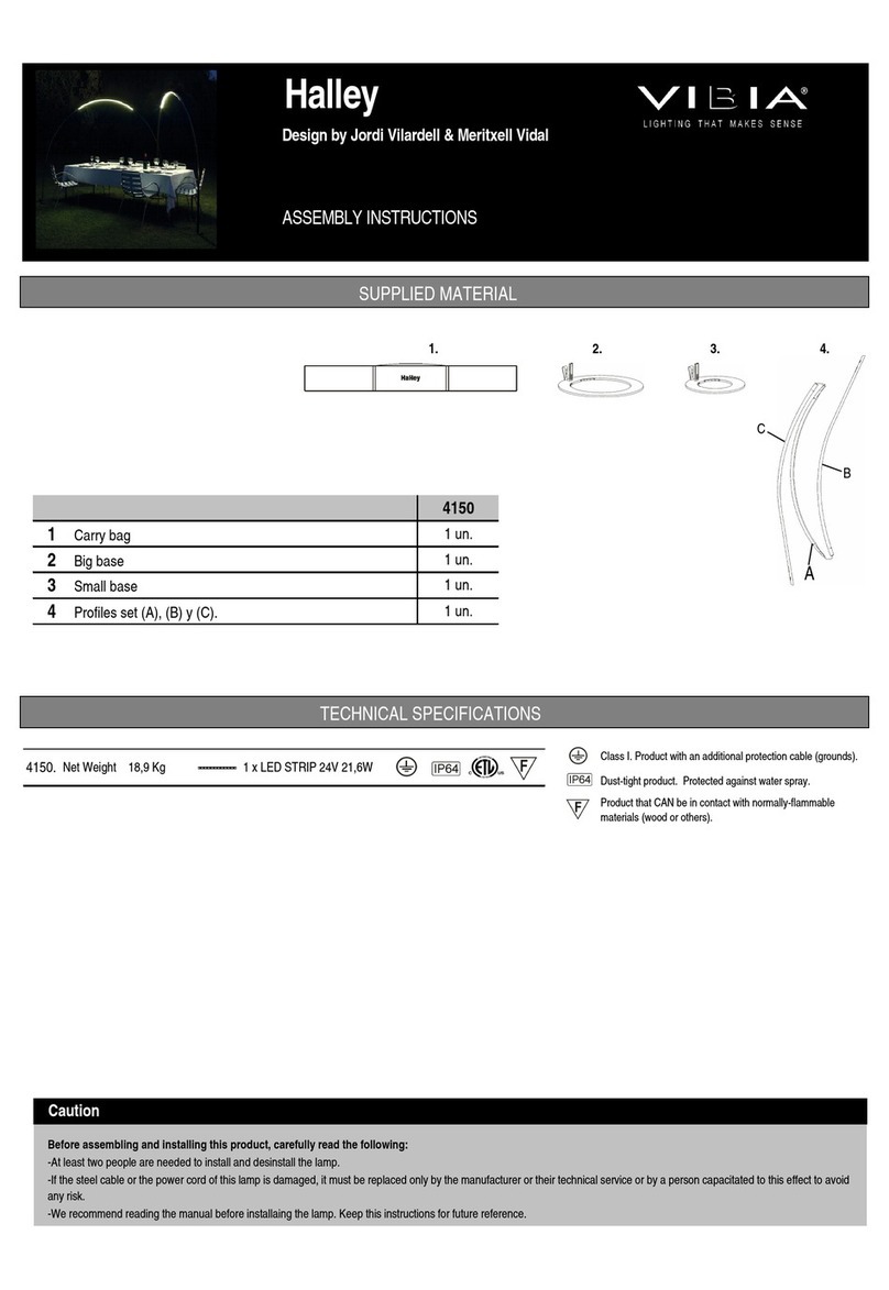
ASSEMBLY INSTRUCTIONS INSTRUCCIONES DE MONTAJE MONTAGEANLEITUNG
4. Realizar la conexión a la red eléctrica, primero desmontar la tapa (H) quitando
los 4 tornillos y segundo, aflojar el prensaca les (I) para poder introducir el ca le
de su instalación y realizar la conexión en las regletas. Por último volver a apretar
el prensaca les y montar la tapa con los 4 tornillos.
NOTA: El modelo va preparado para ser conectado directamente a una toma de
corriente cumpliendo un IP 65. El ca le utilizado de e ser de goma o superior
tipo H05 RN-F de entre 5 y 10 mm. de diámetro.
Volver a montar el pie (E) en la ase (C) siguiendo los pasos contrarios al punto
2 de forma que la caja de conexión (G) pase a través del agujero de la ase y
quede alojada completamente en su caja de registro. Asegurarse de que quede
ien sujeto al anclaje (F) y fijarlo roscando el tornillo (D).
Por último montar la pletina em ellecedor (A) con los tornillos (A) roscándolos sin
ejercer excesiva presión.
5. Para la instalación y mantenimiento de las om illas desenroscar los 6
tornillos con la llave allen suministrada y extraer la tapa (J). Proceder y volver a
montarla roscando los tornillos homogéneamente y apretar para asegurar la
estanqueidad.
Connection to the mains: First remove the cover (H) y unscrewing the four
screws. Secondly, loose the ca le clamp (I) so as to slip your installation ca le
through it and connect it to the connectors. Then tighten again the ca le clamp
and reinstall the cover using the four screws.
NOTE: The product is ready to e directly connected to an IP65 plug. The ca le
used must e made of ru er and type H05 RN-F etween 5 and 10 millimetres
in diameter.
Reinstall the lamp (E) on the ase (C) following the instruction in point 2
ackwards so that the connection ox (G) through the hole on the ase and is not
caught in etween the lamp and the ase. Make sure the lamp is firmly anchored
to the ase (F) and fix it in place using the screw (D). Reinstall the metal strip (A)
with the screws (A). To not screw them to tight.
5. To install and maintain the ul s unscrew the 6 screws with supplied allen key
to free the disc (J). Once finished, fit the disc with the screws, screw them
uniformly and tighten to ensure watertightness.
4. Schließen Sie die Lampe an die Stromversorgung an. Nehmen Sie dazu zuerst
die A deckung (H) durch Lockern der 4 Schrau en a und lockern Sie
anschließend die Ka eleinführung (I), um das Ka el einführen und den Anschluss
an den Leisten durchführen zu können. Befestigen Sie anschließend die
Ka eleinführung wieder und ringen Sie die A deckung mit den 4 Schrau en
wieder an.
HINWEIS: Dieses Modell ist für den direkten Stromanschluss nach Schutzklasse
IP65 ausgelegt. Das verwendete Ka el muss aus Gummi oder einem
höherwertigem Material Typ H05 RN-F mit 5 is 10 mm Durchmesser sein.
Bringen Sie den Fuß (E) wieder am Gestell (C) an. Gehen Sie da ei wie in Punkt
2 vor, jedoch in umgekehrter Reihenfolge, so dass die Leitungsdose (G) durch
die Öffnung im Gestell und vollständig in den Schaltkasten passt. Stellen Sie
sicher, dass sie gut an der Verankerung (F) efestigt ist. Ziehen Sie hierzu die
Schrau e (D) fest.
Bringen Sie anschließend die Verzierungsplatine (A) mit den Schrau en (B)
wieder an. Ziehen Sie diese ohne ü ermäßigen Druck fest.
5. Zwecks Installation oder Austausch der Leuchtmittel lösen Sie die 6 Schrau en
mit dem mitgelieferten Im ußschlüssel und entnehmen Sie die A deckung (J).
Montieren Sie danach wieder die A deckung und schrau en Sie die Schrau en
fest. Festziehen, damit die Dichtigkeit gewährleistet ist.
: MAKE SURE HE LID IS FIRMLY CLOSED O AVOID
MOIS URE.
ASEGURAR EL CORREC O CIERRE DE LA APA PARA
EVI AR POSIBLES FIL RACIONES DE AGUA.
: VERGEWISSERN SIE SICH EINES KORREK EN SCHLIESSENS
DER ABDECKUNG UM EINEN MÖGLICHEN WASSEREIN RI ZU
VERMEIDEN.
