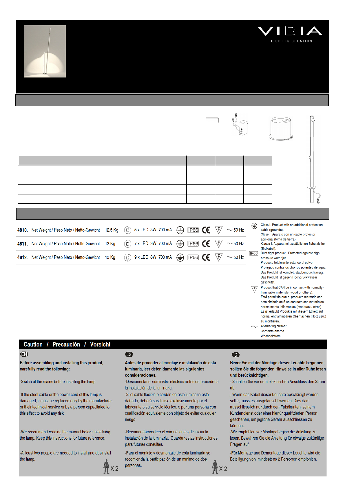
VIBIA Bamboo User manual

SUPPLIE
D MATERIAL MATERIAL SUMINISTRADO
GELIEFERTES MATERIAL
Bamboo
Design by Antoni Arola & Enric Rodríguez
ASSEMBLY INSTRUCTIONS
INSTRUCCIONES DE MONTAJE
MONTAGEANLEITUNG
1.
2.
3.
4.
481 4811 4812
1
Allen key / Llave allen / Inbuss hlüssel 1 un. 1 un. 1 un.
2
Wiring box / Caja de onexión / Klemmenkasten 1 un. 1 un. 1 un.
3
Inset asing / Cuerpo de empotrar / Einbauso kel 1 un. 1 un. 1 un.
4
Tube stru ture / Estru tura Tubo / Röhren-Struktur 2 un. 2 un. 3 un.
TECHNICAL SPECIFICATIONS
ESPECIFICACIONES TÉCNICAS TECHNISCHE DATEN

ASSEMBLY INSTRUCTIONS INSTRUCCIONES DE MONTAJE MONTAGEANLEITUNG
EN
ES
D
1
.
Quitar la tapa (B) desmontando los tres tornillos (A) on la
llave allen suministrada.
2. Realizar un orifi io en el suelo de Ø34,5 m. y 26 m. de
profundidad para poder empotrar el uerpo (C), dejando
preparado debajo un sistema de drenaje de entre 20 y 30 m.
on base de grava, si el terreno es arenoso. En aso de que
se empotre en hormigón, prever el sistema de drenaje más
ade uado.
IMPORTANTE: Realizar la prueba de llenar de agua el orifi io
y esperar 30 minutos, si después de este tiempo no se ha
eva uado todo el agua, ha er un sistema de drenaje
omplementario.
1.
Dismount over (B) by removing the three s rews (A) using
the allen key supplied.
2. Make a hole in the ground of Ø34,5 m and 26 m deep to
set the asing (C) into, and provide a gravel drainage system
20-30 m deep if the ground is sandy. If the lamp is to be set
into on rete, provide for the most suitable drainage system.
IMPORTANT: Carry out a trial by filling the hole with water and
waiting 30 minutes; if the water has not drained away
ompletely by this time, fit an extra drainage system.
1.
Lösen Sie mit dem mitgelieferten Inbuss hlüssel die drei
S hrauben (A) heraus und montieren Sie die Abde kung (B)
ab.
2. Fertigen Sie zum Versenken des Einbautopfes (C) im Boden
eine Öffnung von Ø 34,5 m und 26 m Tiefe an, unterhalb
muss si h bei sandigem Boden ein aus Kies bestehendes
Entwässerungssystem von 20 bis 30 m befinden.
WICHTIG: Ma hen Sie die Probe, indem Sie die Öffnung mit
Wasser füllen und 30 Minuten warten. Ist das Wasser na h
dieser Zeit ni ht vollständig abgelaufen, muss ein zusätzli hes
Entwässerungssystem angelegt werden. Beim Einbau in Beton
ein angemessenes Entwässerungssystem auswählen.
IMPORTANT NOTICE:
Switch of the mains before installing the lamp.
IMPO
RTANTE:
Desconectar el suministro eléctrico antes de realizar la
instalación de la luminaria.
WICHTIG:
Schalten Sie den Strom ab. bevor Sie die
Leuchtenmontage realisieren.
1
2
A
B
C
- Extra drain pipe
-Tubo de drenaje omplementario
-zusätzli hes Entwässerungsrohr
Ø 34,5 m.
26 m.
20 - 30 m.
-
Mains power able
-Cable de su instala ión elé tri a
-Kabel Ihrer Elektroinstallation
- Gravel for drainage
-Grava de drenaje
-Entwässerungskies

C
D
ASSEMBLY INS
TRUCTIONS INSTRUCCIONES DE MONTAJE MONTAGEANLEITUNG
50 m.
3
EN
ES
D
3
.
Introdu ir el uerpo (C) en el agujero
realizado pasando a través de su interior la
manguera de onexión elé tri a (D). Debe
sobresalir del suelo la longitud ne esaria de
manguera para fa ilitar la onexión elé tri a.
Rellenar on pasta el hue o hasta enrasar on
la superfi ie.
NOTA: Tener en uenta la orienta ión de la
base empotrada, uerpo (C), para que queden
los tubos orientados según desee, y no tener
dentro del diámetro indi ado ningún obstá ulo
verti al que pueda interferir en el montaje de los
tubos.
3
.
Insert the asing (C) in the resulting hole,
running the power able (D) through inside it.
Enough length of able must sti k out above the
ground to make the power onne tion.
Fill in the hole with ement until it is flush with
the ground.
NOTE: Pay attention to whi h way the inset
base, asing (C), is fa ing, so that the tubes
fa e the right way, and make sure there is no
verti al obje t within the diameter shown whi h
might interfere with the installation of the tubes.
3
.
Setzen Sie nun den Einbautopf (C) –
zusammen mit dem si h in seinem Innern
befindenden Stroms hlau h (D) – in die
angefertigte Öffnung ein. Der Stroms hlau h
muss hierbei soweit über den Boden
hinausragen, dass problemlos der elektris he
Ans hluss dur hgeführt werden kann.
Füllen Sie nun die Öffnung mit Spa htelmasse
auf, sodass sie bündig mit der Oberflä he
abs hließt.
HINWEIS: Bea hten Sie die Ausri htung des
eingebauten Lampenfußes, des Einbautopfes
(C), damit die Rohre wie gewüns ht
ausgeri htet sind und si h innerhalb des
angezeigten Dur hmessers kein senkre htes
Hindernis befindet, das die Montage der Rohre
behindern könnte.
Ø 50 m
Ø 38 m
Ø 47,5 m
Ref. 4810
Ref. 4811
Ref. 4812

ASSEMBLY INSTRUCTIONS INSTRUCCIONES DE MONTAJE MONTAGEANLEITUNG
EN
ES
D
4
.
Realizar la onexión elé tri a:
Primero: Desmontar los 4 tornillos de la aja de
onexión para extraer la tapa (E).
Segundo: Aflojar el prensa ables (F) para introdu ir el
able (D) en la aja de onexión.
Ter ero: Realizar la onexión elé tri a en el terminal
(G).
IMPORTANTE: El modelo va preparado para ser
one tado dire tamente a una toma de orriente
umpliendo un IP 65. El able utilizado debe ser de
goma o superior tipo H05 RN-F <HAR> de entre 7 y 12
mm. de diámetro.
5. Una vez realizadas todas las onexiones, volver a
apretar fuertemente el prensa ables (F).
Montar la tapa (E) asegurándola on los 4 tornillos.
6. Introdu ir la aja de onexiones errada y a omodar
los ables en el interior del uerpo empotrado.
Dejar los one tores (H) apoyados en el exterior.
4
.
Make the ele tri al onne tion:
One: Remove the 4 s rews from the wiring box and
open up the over (E).
Two: Loosen the able gland (F) in order to insert the
able (D) into the wiring box.
Three: Make the ele tri al onne tion in the box (G).
IMPORTANT: This model is ready for dire t onne tion
to an IP 65- lass power point. The able used must be
H05 RN-F <HAR> or better rubber, between 7 and
12mm in diameter.
5. After making all the onne tions, tighten up the
able gland (F) firmly on e more.
Fit the over (E) with the 4 s rews.
6. Insert the sealed wiring box and fit the ables inside
the asing set into the ground.
Leave the onne tors (H) resting outside.
4
.
Führen Sie den Stromans hluss wie folgt dur h:
Erstens: Lösen Sie vom Klemmenkasten die 4
S hrauben und entfernen Sie den De kel (E).
Zweitens: Lo kern Sie die Kabelklemmen (F), um dann
das Kabel (D) einzuführen und die Verbindung im
Klemmenkasten herzustellen.
Drittens: Führen Sie den Ans hluss ans Stromnetz
dur h Kasten (G).
WICHTIG: Das Modell ist für den direkten Ans hluss
an eine Ste kdose mit S hutzgrad IP 65 konzipiert.
Das verwendete Stromkabel muss mindestens eine
Gummiummantelung des Typs H05 RN-F <HAR> mit
einem Dur hmesser zwis hen 7 und 12 mm aufweisen.
5. Na hdem alle Kabel anges hlossen sind, die
Kabelklemmen (F) wieder fest zudrü ken.
Bringen Sie den De kel (E) wieder mithilfe der 4
S hrauben an.
6. Führen Sie den vers hlossenen Klemmenkasten in
den Einbautopf ein und verlegen Sie die Kabel.
Legen Sie die Ste kverbinder (H) außen ab.
5
E
D
F
G
E
F
4
H
6

ASSEMBLY INST
RUCTIONS INSTRUCCIONES DE MONTAJE MONTAGEANLEITUNG
EN
ES
D
7
.
Insertar los tubos (I) de la luminaria en
los pivotes (J) de la base, de forma que los
one tores queden fuera.
8. Girar los tubos (I) on la orienta ión de
los fo os ha ia la dire ión que desee
iluminar.
IMPORTANTE: No oger por los fo os para
girar el tubo.
Apretar las tuer as (K) de las bridas
montadas en la base, de esta forma
quedan fijados los tubos, sin posibilidad de
ningún movimiento. Para fa ilitar la
opera ión levantar por el lado on la mano
libre el dis o de goma (L).
NOTA: Para el apriete se puede utilizar una
llave de arra a.
7
.
Insert the tubes (I) of the light fitting into
the pivots (J) in the base, so that the
onne tors remains outside.
8. Rotate tubes (I) to point the spotlights in
the dire tion to be lit.
IMPORTANT: Don´t rotate the tube by the
spotlights
Tighten the nuts (K) on the lamps fitted in
the base, so that the tubes are fixed in
pla e and annot move at all. To make this
easier, use your free hand to lift up the side
of rubber dis (L).
NOTE: A rat het spanner an be used for
tightening.
7
.
Setzen Sie die Rohre (I) der Leu hte so
auf die Zapfen (J) des Fußes, dass die
Ste kverbinder außen bleiben.
8. Drehen Sie die Rohre (I) so und ri hten
Sie die Strahler so aus, dass diese in die
gewüns hte Ri htung leu hten.
WICHTIG: Ni ht die Strahler nützen um
den S hlau h zu drehen.
Ziehen Sie die Muttern (K) der am Fuß
montierten Flans he an, so bleiben die
Rohre gut befestigt und können ni ht
bewegt werden. Heben Sie zum Erlei htern
des Vorgangs mit der freien Hand die
Gummis heibe an (L).
HINWEIS: Zum Fests hrauben kann au h
eine Rats he verwendet werden.
J
I
7
I
K
L
8

ASSEMBLY INSTRUCTIONS INSTRUCCIONES DE MONTAJE MONTAGEANLEITUNG
EN
ES
D
9
.
Cone tar los terminales (H) e introdu ir en el interior
del uerpo empotrado.
1 . Empujar en ada tubo el dis o de goma (L)
deslizándolo ha ia abajo por el tubo hasta que haga
tope en la brida montada.
NOTA: Si quedan restos de goma negra en el tubo se
pueden limpiar on un trapo humede ido en agua. No
usar produ tos de limpieza que puedan dañar la
superfi ie.
9
.
Conne t the terminals (H) and insert them inside the
asing set into the ground.
1 . Push rubber dis (L) over ea h tube, sliding it down
along the tube until it is against the lamp fitted.
NOTE: If any tra es of bla k rubber are left in the tube
they an be leaned off with a loth dampened in water.
Do not use leaning produ ts whi h an damage the
surfa e.
9
.
Ste ken Sie die Ste kverbinder (H) zusammen und
setzen Sie diese in den Einbautopf ein.
1 . S hieben Sie an jedem Rohr die Gummis heibe (L)
na h unten, bis sie auf dem montierten Flans h aufsitzt.
HINWEIS: Sollten s hwarze Gummireste am Rohr
haften bleiben, können diese mit einem feu hten Tu h
entfernt werden. Verwenden Sie keine
Reinigungsmittel, da diese die Oberflä he bes hädigen
könnten.
1
H
1
st
2
nd
9
L

ASSEMBLY INSTRUCTIONS INSTRUCCIONES DE MONTAJE MONTAGEANLEITUNG
12
EN
ES
D
11.
Fíjese en la posi ión de los taladros de fija ión de
la tapa (B), para introdu irla de forma orre ta por la
parte superior de los tubos, de forma que al deslizarla
hasta la base oin idan los orifi ios de fija ión on
los de la base empotrada. Tiene montadas unas
juntas de goma en los orifi ios para que no rayen los
tubos, extraer y dese has estas juntas al final de todo
el pro eso.
NOTA: Los tubos tienen un me anismo en la base,
de forma que se pueden mover lo sufi iente para
poder introdu ir la tapa (B). No mover un solo tubo,
se tienen que a ompañar un po o todos.
12. Fijar la tapa (B) on los tres tornillos (A) usando
la llave allen suministrada.
11.
Note the position of the fixing holes in the over
(B) and fit it orre tly over the top of the tubes so that
when it is slid down to the base the said fixing holes
line up with those in the inset base. It has rubber
seals in the openings so that the tubes are not
s rat hed. Remove and dis ard these seals on e the
pro ess is omplete.
NOTE: The tubes have a me hanism in the base to
allow them to move enough to be able to fit the over
(B). Do not move one tube alone; they must all move
a little at the same time.
12. Fix over (B) in pla e with the three s rews (A)
using the allen key supplied.
11.
Bea hten Sie die Position der Gewindebohrungen
auf der Abde kung (B), so kann diese korrekt von
oben auf die Rohre ges hoben werden und die
Befestigungsöffnungen stimmen mit denen des
eingebauten Leu htenfußes überein. Damit dabei die
Rohre ni ht zerkratzt werden, sind auf den Öffnungen
einige Gummidi htungen befestigt. Nehmen Sie na h
Beendigung des Vorgangs die Di htungen heraus
und entsorgen Sie sie.
HINWEIS: Die Rohre verfügen an ihrem Fuß über
einen Me hanismus. Dur h diesen können sie weit
genug bewegt werden, um die Abde kung (B)
einzuführen. Bewegen Sie ni ht nur ein Rohr,
sondern alle glei hzeitig.
12. Befestigen Sie die Abde kung (B), indem Sie die
drei S hrauben (A) mit dem mitgelieferten
Inbuss hlüssel anziehen.
B
A
B
1
st
2
nd
B
3
rd
11
This manual suits for next models
3
Table of contents
Other VIBIA Outdoor Light manuals

VIBIA
VIBIA Alpha 7940 User manual

VIBIA
VIBIA Warm 4895 User manual

VIBIA
VIBIA Palma User manual

VIBIA
VIBIA Warm User manual

VIBIA
VIBIA Break User manual

VIBIA
VIBIA Break User manual

VIBIA
VIBIA Brisa User manual

VIBIA
VIBIA Skan 0250 User manual

VIBIA
VIBIA Palo Alto User manual

VIBIA
VIBIA Empty 4125 User manual

VIBIA
VIBIA Halley User manual

VIBIA
VIBIA Jazz User manual

VIBIA
VIBIA Wind User manual

VIBIA
VIBIA Break User manual

VIBIA
VIBIA Brisa Quick start guide

VIBIA
VIBIA Warm 4900-INC User manual

VIBIA
VIBIA Meridiano User manual

VIBIA
VIBIA Plis Outdoor User manual

VIBIA
VIBIA Swing 0503 User manual

VIBIA
VIBIA Class 2800 User manual