ViewZ VZ-CM308-B User manual

VZ-CM308
VZ-CM308 series INSTALLATION INSTRUCTIONS
Telescopic Ceiling Mount with length, rotation and tilt adjust
VZ-CM308-B (for Black Color)
VZ-CM308-W (for White Color)
VZ-CM-EB (Optional Extension Pole set for Black Color)
VZ-CM-EW (Optional Extension Pole set for White Color)

2Installation InstructionsVisit the ViewZ USA website at http://www.viewzusa.com
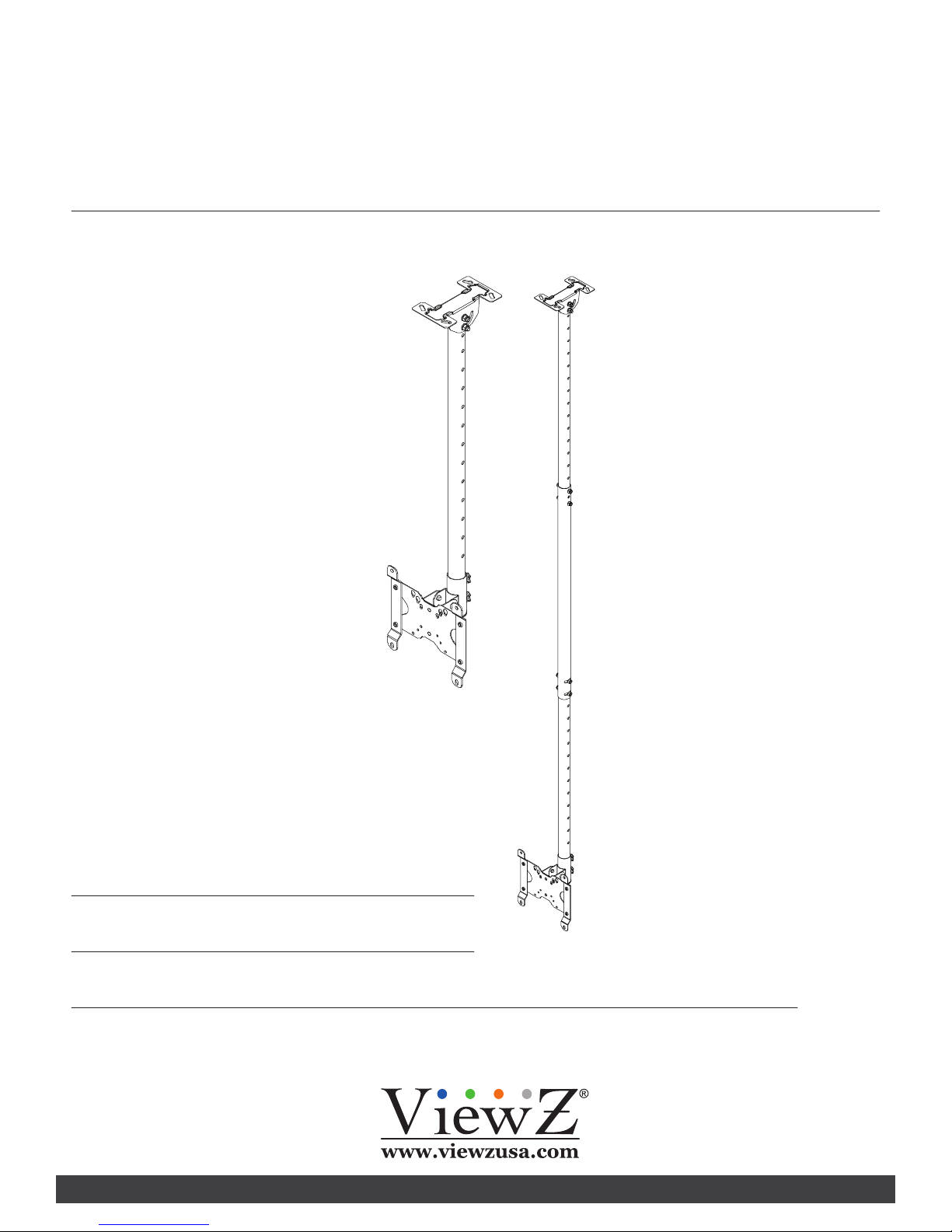
CM 308 series
Weight Limit 2
Warning Statements 2
Ceiling Mount info 3
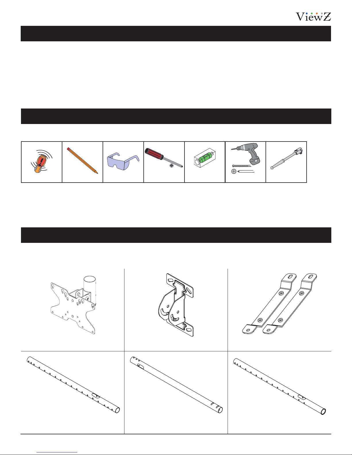
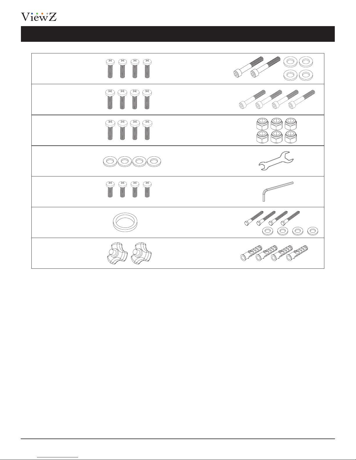
Assembly Component List 3
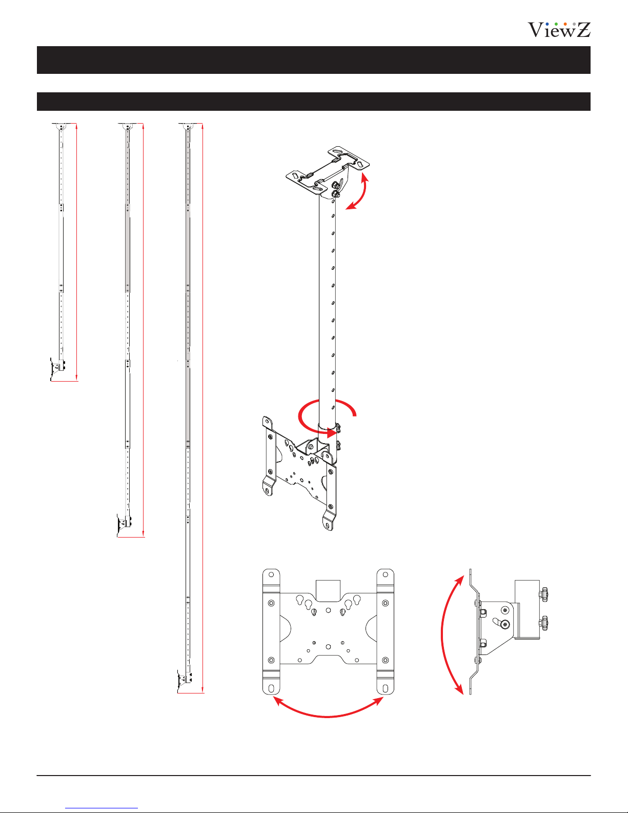
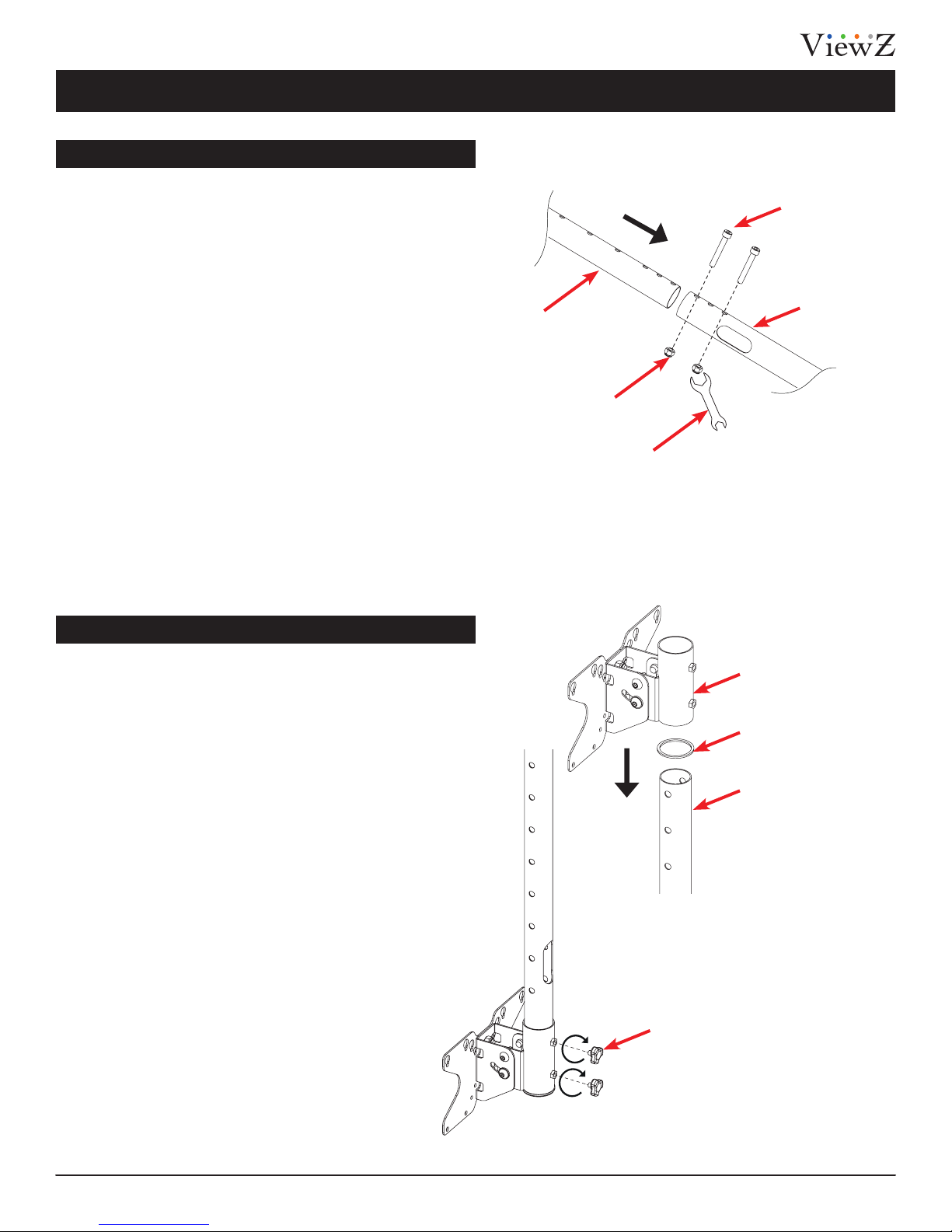
6Installing the Mount
7Leveling the Pole
7Mounng Monitor-Bracket to Pole
9Installing Monitor to the Pole
Features 5
Warranty 10
Maximum Monitor Weight:
66.1 lbs
PRIOR TO THE INSTALLATION OF THIS PRODUCT, THE INSTALLATION INSTRUCTIONS MUST BE READ AND COMPLETELY UNDERSTOOD. KEEP THESE
INSTALLATION INSTRUCTIONS IN AN EASILY ACCESSIBLE LOCATION FOR FUTURE REFERENCE.
SAFETY MEASURES MUST BE PRACTICED AT ALL TIMES DURING THE ASSEMBLY OF THIS PRODUCT. USE PROPER SAFETY EQUIPMENT AND TOOLS
FOR THE ASSEMBLY PROCEDURE TO PREVENT PERSONAL INJURY.
At least two qualied people should perform the assembly procedure. Personal injury and/or property damage can result from dropping or
mishandling the at-panel.
CHANGES OR MODIFICATIONS NOT EXPRESSLY APPROVED BY THE PARTY RESPONSIBLE FOR COMPLIANCE COULD VOID THE USERS AUTHORITY TO
OPERATE THE EQUIPMENT.
If mounng to wall studs or ceiling studs, make sure that the mounng screws are anchored into the center of the wall studs or ceiling studs. Use
of an edge-to-edge stud nder is recommended.
Using replacement parts or accessories other than from the manufacturer may void the warranty.
Be aware of the mounng environment. If drilling and/or cung into the mounng surface, always make sure that there are no electrical wires in
wall. Cung or drilling into an electrical line may cause serious personal injury.
Make sure there are no water or natural gas lines inside the wall where the mount is to be located. Cung or drilling into a water or gas line may
cause severe property damage or personal injury.
This product is intended for indoor use only. Use of this product outdoors could lead to product failure and/or serious personal injury.
Do not install near sources of high heat. Do not install on a structure that is prone to vibraon, movement or chance of impact.
Contact ViewZ with any quesons:
(888) 998-4399
techsupport@viewzusa.com
PROPER INSTALLATION PROCEDURE BY A QUALIFIED SERVICE TECHNICIAN MUST BE FOLLOWED, AS OUTLINED IN THESE INSTALLATION
INSTRUCTIONS. FAILURE TO DO SO COULD RESULT IN PROPERTY DAMAGE, SERIOUS PERSONAL INJURY, OR EVEN DEATH.
ViewZ USA DOES NOT WARRANT AGAINST DAMAGE CAUSED BY THE USE OF ANY ViewZ USA PRODUCT FOR PURPOSES OTHER THAN THOSE
FOR WHICH IT WAS DESIGNED OR DAMAGE CAUSED BY UNAUTHORIZED ATTACHMENTS OR MODIFICATIONS, AND IS NOT RESPONSIBLE FOR
ANY DAMAGES, CLAIMS, DEMANDS, SUITS, ACTIONS OR CAUSES OF ACTION OF WHATEVER KIND RESULTING FROM, ARISING OUT OF OR IN ANY
MANNER RELATING TO ANY SUCH USE, ATTACHMENTS OR MODIFICATIONS.
Weight Limit
Warning Statements
Contents
.........................................................................................................................................................................................................
............................................................................................................................................................................................
...................................................................................................................................................................................................
....................................................................................................................................................................................
............................................................................................................................................................................................
...............................................................................................................................................................................................
......................................................................................................................................................................
.............................................................................................................................................................................
.................................................................................................................................................................................................................
...............................................................................................................................................................................................................

3Installation Instructions Visit the ViewZ USA website at http://www.viewzusa.com
A
D
B
E
C
F
CM 308 series
This bracket is designed to mount a monitor from the ceiling structure. It can be used with the exisng truss structure of the building
or in conjuncon with a channel strut. There are four lengths of brackets available.
The following tools may be required depending on your installaon.
• Part #
• Part #
• Part #
• Part #
VZ-CM308-B
VZ-CM308-W
VZ-CM-EW
VZ-CM-EB
Length of 3' to 8'
Length of 3' to 8'
Length of 3' to 5.2' Oponal Extension Pole Set
Your ViewZ mount product is shipped with all proper installaon hardware and components. If there are parts missing
and/or damaged, please stop the installaon and contact ViewZ USA at (888)-998-4399.
Electronic Stud Finder
Monitor Hold Bracket (1 pc.)
Top Pole (1 pc.)
Wall/Ceiling Mount Bracket (1 pc.)
Middle Pole (1 pc.)
Monitor Hold Bracket (2 pc.)
Boom Pole (1 pc.)
Protecve Eye-wearPencil Phillips Screwdriver Level Portable Drill / Bit Socket Wrench
Assembly Components
Installation Tools
Telescopic Ceiling Mount Info

4Installation InstructionsVisit the ViewZ USA website at http://www.viewzusa.com
CM 308 series
Assembly Components (cont’d)
M5 x L15 mm Screw
(Qty 4)
M8 x L50 x φ 10
(Qty 4) - 8.8 grade
M6 x L15 mm Screw
(Qty 4)
M8 Lock Nut
(Qty 6)
φ 16 x φ 6.2 x 1.5
Washers (Qty 4) Open Wrench (Qty 1)
M6 x L12 mm Screw
(Qty 4)
6 mm Allen Wrench
(Qty 1)
φ 44 x φ 38.5 x 2.0
Washers (Qty 1)
M8 x L70 x φ 10
(Qty 4) - 8.8 grade
φ 16 x φ 8.2 x 1.5
Washers (Qty 4)
M6 x L10 mm Lock Screw
(Qty 2) Anchor (Qty 4)
M4 x L15 mm Screw
(Qty 4)
M8 x L55 x φ 10
(Qty 2) - 8.8 grade
φ 16 x φ 8.2 x 1.5
Washers (Qty 4)
G N
H O
I P
J Q
K R
L S
M T

5Installation Instructions Visit the ViewZ USA website at http://www.viewzusa.com
8.03 ft / 96.45” / 2450 mm (Max) ~ 3.08 ft / 37.0” / 940 mm (Min)
13 ft (Max) ~ 3.08 ft / 37.0” / 940 mm (Min)
18 ft (Max) ~ 3.08 ft / 37.0” / 940 mm (Min)
CM 308 series
Extension Pole Configuration / Tilt, Swivel
Features
Tilng ± 5°
PAN Rotaon 360°
Tilng 0-90°
Tilng -5° ~ +45°
D DD
E EE
D DF
E E
E
F D
F
8 ft
(Basic)
13 ft
(Optional)
18 ft
(Optional)

6Installation InstructionsVisit the ViewZ USA website at http://www.viewzusa.com
CM 308 series
Securing Mount to Building
Secure Mounting to Brick/Concrete or Wood
Installation
1) Insert screw to Wall/Ceiling mount bracket with wahsers when you
setup the position of top pole.
2) You can adjust pole angle between 0⁰ and 90⁰.
3) Tighten the M8 lock nut using a open-wrench.
Brick or Concrete Wall/Ceiling Mounting
1) Insert anchors to truss or channel strut (brick, concrete or wood)
2) Insert screw to Wall/Ceiling mount bracket with wahsers rod between
truss gap or hole in channel strut.
3) Place washer over the threaded rod and then tighten using wrench.
Wood Mounting
1) Insert screw to Wall/Ceiling mount bracket between truss gap or
hole in channel strut.
Caution: Please be extra cautious when finding a mountable
position in the ceiling. Dry-wall or weak-wood material
cannot bear the weight of pole & monitor.
P Lock Nut
N Screws & Washers
N Washers
B Wall/Ceiling Mount Bracket
D Top Pole
Q Open Wrench
T Anchors
S Screws & Washers
S Screws & Washers
Truss / Channel Struct
Brick or Concrete
Wood

7Installation Instructions Visit the ViewZ USA website at http://www.viewzusa.com
CM 308 series
Leveling the Pole (Top & Middle)
Mounting Monitor-Hold-Bracket(Vesa Plate) to Pole
Installation
1) You can ensure the pole is properly aligned by tightening the lock
screws/nuts between top & middle, middle & bottom poles.
2) Place a level on poles(top & bottom) and tighten the screws/nuts (see
illustration on the right).
3) Check and adjust 2 adjacent sides of the pole until it is plumb in each
direction.
1) Hold the bottom pole and put 1-3/4" washer between vesa brack and
bottom pole (see illustration on the right).
2) Gently push the vesa bracket to bottom pole. Vesa bracket is bigger
than bottom pole circumference
3) You can rotate vesa plate before locking. If you have a desired
direction for the plate, please rotate vesa bracket.
4) After setting the position, use M6xL10 lock screws and lock the vesa
plate.
*NOTE: Avoid over-tightening which can cause the pole to cave.
P Lock Nut
D Top Pole
O Screws
E Middle Pole
F Boom Pole
M M6xL10 lock
screws
L φ 44 x φ 38.5 x 2.0
mm Washer
E Monitor Hold
Bracket
Q Open Wrench

8Installation InstructionsVisit the ViewZ USA website at http://www.viewzusa.com
CM 308 series
Leveling Pole (Bottom & Middle)
Rotation
Installation
1) You can ensure the pole is properly aligned by tightening the lock
screws/nuts between middle & bottom poles.
2) Place a level on poles (middle & bottom) and tighten the screws/nuts
(see illustration on the right).
3) Check and adjust 2 adjacent sides of the pole until it is plumb in each
direction.
1) Hold the lower pole (where it connects to the monitor) and turn
two lock screws counter-clockwise to loosen the VESA plate (see
illustration on left below). Then, rotate vesa plate to set the position.
2) Once set in a desired position, lock the two lock-screws by turing
clockwise.
Le Loosen
Hold vesa plate posion
and turn two lock-screws as
clockwise to set the posion
Hold lower pole secon, turn
two lock-screws as counter-
clockwise to rotate vesa plate
Right Tighten
O M8 x L50 Screws
F Boom Pole
P M8 Lock Nut
E Middle Pole
Q Open Wrench

9Installation Instructions Visit the ViewZ USA website at http://www.viewzusa.com
CM 308 series
Installation
G, H, I Screws
G, H, I Screws
J Washer
C - Monitor Hold Bracket
Direct Installation
Monitor Hold Bracket Installation
1) Applicable VESA pattern - 50 x 50, 75 x 75, 100 x 100, 200 x 100
If your monitor supports a VESA plate already mounted on the back,
simply ensure the four M4/M5/M6 screws are in place and tightened.
If the mount is not already attached, connect it using the supplied
M4/M5/M6 VESA screws (4-places).
1) Applicable VESA pattern - 200 x 100, 200 x 200
(Optional 400 x 400 available)
This stand is intended for use only with products that are
lighter than maximum weight indicated. Usage with
products heavier than the maximum weight indicated
may result in instability causing possible injury. This
product is intended to mount to a steel support truss, or
channel strut (Brick, Concrete or Wood)
Caution: Some installations may require running power and
video cables prior to attaching the monitor bracket to the pole. If
this is the case, do so before continuing to step 2.
Caution: Some monitors require specific length of screws.
Please check the affordable screw length before installing.
Max Load:
66.1 lbs / 30.0 kg
2) Install the M4 x L15 mm screw, washers, and monitor-hold bracket
(if necessary) into the upper slotted hole according to the illustration
on the right. You will need to use Phillips screwdriver or mobile
screwdriver to fully tighten in the next step.
3) Tighten the fasteners to secure the monitor at the desired angle.
*NOTE: Avoid over-tightening which can cause monitor damage

10 Installation InstructionsVisit the ViewZ USA website at http://www.viewzusa.com
CM 308 series
Warranty
What and Who is Covered by this Limited Warranty and for How Long
ViewZ USA warrants this product to be free from defects in material and workmanship for the lifeme of the original owner of this
product. The limited warranty is valid only for the original purchaser of the product.
What ViewZ USA Will Do
At the sole opon of ViewZ USA, ViewZ USA will repair or replace any product or product part that is defecve. If ViewZ USA chooses
to replace a defecve product or part, a replacement product or part will be shipped to you at no charge, but you must pay any labor
costs.
What is Not Covered; Limitaons
ViewZ USA DISCLAIMS ANY LIABILITY FOR DAMAGE TO MOUNTS, ADAPTERS, DISPLAYS, PROJECTORS, OTHER PROPERTY, OR
PERSONAL INJURY RESULTING, IN WHOLE OR IN PART, FROM IMPROPER INSTALLATION, MODIFICATION, USE OR MISUSE OF ITS
PRODUCTS.
ViewZ USA DISCLAIMS ALL OTHER WARRANTIES, EXPRESS OR IMPLIED, INCLUDING WARRANTIES OF MERCHANTABILITY AND FITNESS
FOR A PARTICULAR PURPOSE. ViewZ USA IS NOT RESPONSIBLE FOR INCIDENTAL OR CONSEQUENTIAL DAMAGES, INCLUDING BUT
NOT LIMITED TO, INABILITY TO USE ITS PRODUCTS OR LABOR COSTS FOR REMOVING AND REPLACING DEFECTIVE PRODUCTS OR
PARTS. SOME STATES DO NOT ALLOW THE EXCLUSION OR LIMITATION OF INCIDENTAL OR CONSEQUENTIAL DAMAGES, SO THE
ABOVE LIMITATION OR EXCLUSION MAY NOT APPLY TO YOU.
What Customers Must Do for Limited Warranty Service
If you discover a problem that you think may be covered by the warranty you MUST REPORT it in wring to the address below within
thirty (30) days. Proof of purchase (an original sales receipt) from the original consumer purchaser must accompany all warranty
claims. Warranty claims must also include a descripon of the problem, the purchaser’s name, address, and telephone number.
General inquiries can be addressed to ViewZ USA Customer Service at 1-888-998-4399. Warranty claims will not be accepted over the
phone or by fax.
How State Law Applies
THIS WARRANTY GIVES YOU SPECIFIC LEGAL RIGHTS, AND YOU MAY ALSO HAVE OTHER RIGHTS WHICH VARY FROM STATE TO STATE.
ViewZ USA intends to make this manual accurate and complete. However, ViewZ USA makes no claim that the informaon contained
herein covers all details, condions or variaons, nor does it provide for every possible conngency in connecon with the
installaon or use of this product. The informaon contained in this document is subject to change without noce or obligaon of
any kind. ViewZ USA makes no representaon of warranty, expressed or implied, regarding the informaon contained herein. ViewZ
USA assumes no responsibility for accuracy, completeness or suciency of the informaon contained in this document.
ViewZ USA
LIMITED LIFETIME WARRANTY
ViewZ USA
An: Warranty Claim
177 W. Orangethorpe Ave.
Placena, CA 92870
NORTH AMERICA
177 W. Orangethorpe Ave.
Placena, CA 92870
USA and Canada
Phone: 1-888-998-4399
Fax: 1-714-996-1138
Other Locaons
Phone: (001) 888-998-4399
Fax: (001) 714-996-1138
© ViewZ USA
Disclaimer
Contact Us
This manual suits for next models
4
Table of contents
Other ViewZ TV Mount manuals

ViewZ
ViewZ VZ-WM11 User manual

ViewZ
ViewZ VZ-CMKiT-01 User manual

ViewZ
ViewZ VZ-CMKiT-04 User manual

ViewZ
ViewZ VZ-WM71 User manual

ViewZ
ViewZ VZ-WM50 User manual

ViewZ
ViewZ VZ-CM-V1 User manual

ViewZ
ViewZ VZ-CMKiT-02 User manual

ViewZ
ViewZ VZ-AM03 User manual

ViewZ
ViewZ VZ-WM60 User manual

ViewZ
ViewZ VZ-CM-V3 User manual