manuals.online logo
Brands
  1. Home
  2. •
  3. Brands
  4. •
  5. Vimar
  6. •
  7. Intercom System
  8. •
  9. Vimar Elvox 12TS Assembly instructions

Vimar Elvox 12TS Assembly instructions

Manuale installatore - Installer guide - Manuel installateur
Technisches Handbuch - Instrucciones instalador - Manual do instalador
moduli per targa Galileo 2 FILI ELVOX
123
456
789
0
ABC DEF
GHIJKL MNO
PQRS TUV WXYZ
+
R
CANC
8051
(1 pulsante)
(1 push-button)
(1 poussoirs)
(1 Taste)
(1 pulsador)
(1 botão)
8052
(2 pulsanti)
(2 push-buttons)
(2 poussoirs)
(2 Tasten)
(2 pulsadores)
(2 botões)
12TS - 12TS.B
(4 pulsanti)
(4 push-buttons)
(4 poussoirs)
(4 Tasten)
(4 pulsadores)
(4 botões)
8054
(4 pulsanti)
(4 push-buttons)
(4 poussoirs)
(4 Tasten)
(4 pulsadores)
(4 botões)
8053
(3 pulsanti)
(3 push-buttons)
(3 poussoirs)
(3 Tasten)
(3 pulsadores)
(3 botões)
moduli per targa Galileo 2 FILI ELVOX
123
456
789
0
ABC DEF
GHIJKL MNO
PQRS TUV WXYZ
+
R
CANC
moduli per targa Galileo 2 FILI ELVOX
123
456
789
0
ABC DEF
GHIJKL MNO
PQRS TUV WXYZ
+
R
CANC
moduli per targa Galileo 2 FILI ELVOX
123
456
789
0
ABC DEF
GHIJKL MNO
PQRS TUV WXYZ
+
R
CANC
12TS, 12TS.B, 8051, 8052, 8053, 8054
Unità elettronica supplementare con 4 pulsanti
Additional electronic unit with 4 buttons
Unité électroniques supplementaires 4 boutons
Zusätzliche Elektronikeinheit mit 4 Tasten
Unidad electrónica adic. con 4 pulsad.
Unidade eletrônica adicional com 4 botões
MODULI SUPPLEMENTARI
Art. 12TS, 12TS.B
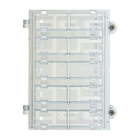
L’articolo 12TS è un modulo supplementare
con pulsanti in singola la da collegare alle
unità elettroniche base:
- Art. 13F3, 13F5 e Art. 12F3, 12F5 per tar-
ghe DUE FILI ELVOX
- Art. 1283, 1285, per targhe DIGIBUS.
L’articolo 12TS.B è un modulo supplemen-
tare con pulsanti da collegare alle unità elet-
troniche base Art. 13F3.B, 13F5.B, 13A4.B,
13A7.B per targhe DUE FILI ELVOX.
Il modulo supplementare si utilizza per l’e-
spansione del numero dei pulsanti di chia-
mata, essi vengono collegati uno di seguito
all’altro per mezzo dei cablaggi forniti con
gli stessi moduli per poi collegarsi all’unità
elettronica tramite il cablaggio presente nel
lato inferiore dell’unità elettronica stessa.
(vedi Fig. 1).
Per unire i moduli art. 12TS e ssarli al telaio
della placca serie 1200 si deve usare il tra-
versino nero art. R693 fornito di serie.
La Fig. 3 ed il particolare 2 indicano come
si agganciano due moduli con l’apposito
traversino.
ADDITIONAL MODULES
Art.12TS, 12TS.B
Type 12TS is an additional module with
push-buttons in one row to connect to the
electronic basic units:
- Types 13F3, 13F5 and types 12F3, 12F5
for DUE FILI ELVOX (Two Wire Elvox)
entrance panels
- Types 1283, 1285 for DIGIBUS entrance
panels.
Article 12TS.B is an additional module
with push buttons to be connected to the
basic electronic units Art. 13F3.B, 13F5.B,
13A4.B, 13A7.B for ELVOX DUE FILI en-
trance panels.
The additional modules are used to extend
the number of call push-buttons; they are
connected one after the other by means
of cables supplied with the same modules
and to be connected to the electronic unit
through the cabling present on the lower
side of the same electronic unit (see Fig. 1).
To join modules type 12TS and x them to
the plate bezel series 1200 use the black
cross bar type R693 supplied as standard.
Fig. 3 and Detail 2 show how to hook two
modules with proper cross bar.
MODULES SUPPLEMENTAIRES
Art. 12TS, 12TS.B
L’Art. 12TS est un module supplémentaire
avec boutons-poussoirs sur une rangée à
raccorder aux unités électroniques base :
- Art. 13F3, 13F5 et Art. 12F3, 12F5 pour
plaques de rue DUE FILI ELVOX (Deux
Fils Elvox)
- Art. 1283 et 1285 pour plaques de rue DI-
GIBUS.
L’article 12TS.B est un module supplémen-
taire avec boutons à connecter aux unités
électroniques de base Art. 13F3.B, 13F5.B,
13A4.B, 13A7.B pour les platines DUE FILI
ELVOX.
Les modules supplémentaires sont utilisés
pour augmenter le nombre de boutons-pous-
soirs d’appel; ils sont raccordés l’un après
l’autre au moyen des câblages fournis avec
les mêmes modules pour être raccordés à
l’unité électronique par l’intermédiaire du
câblage présent dans le côté inférieur de la
même unité électronique (voir Fig. 1).
Pour joindre les modules Art. 12TS et les
xer au châssis de la plaque série 1200 il
faut utiliser la traverse noire Art. R693 four-
nie de série.
La Fig. 3 et le détail 2 indiquent comment
il faut accrocher deux modules avec la tra-
verse appropriée.
MODULI SUPPLEMENTARI
Art. 8051, 8052, 8053, 8054
Gli articoli 8051, 8052, 8053, 8054, sono
moduli supplementari con pulsanti di tipo tra-
dizionale in singola la, da collegare ai mo-
duli base per le seguenti targhe elettroniche:
- DUE FILI ELVOX art. 89F3/…, 89F5/…
- DigiBus 8843/…, 8845/…
- Digit 2 Wires 8B63
Il moduli supplementari si utilizzano per
l’espansione del numero dei pulsanti di
chiamata, essi si collegano uno di seguito
all’altro per mezzo dei cablaggi forniti con
gli stessi moduli per poi collegarsi all’unità
elettronica tramite il cablaggio presente nel
lato inferiore dell’unità (vedi g. 2).
N.B. PER I TELAI PORTAMODULI ART.
8082, ART. 8083, ART. 8093 SI DO-
VRANNO USARE I TRAVERSINI DI AG-
GANCIO NERI ART. R693 (VEDI *).
PER I TELAI PORTAMODULI PER 4 O PIU’
MODULI (ART. 8084 E 8094) SI DOVRA’
USARE ANCHE IL TRAVERSINO DI AG-
GANCIO BIANCO ART. R694 (VEDI **). I
moduli supplementari nella parte posteriore
presentano dei punti di ssaggio evidenziati
nel particolare 1 di Fig. 1b. Detti ssaggi
dovranno essere effettuati solamente nei
moduli centrali come indicato nell’esempio
di Fig. 1 e non per il 1° e l’ultimo modulo.
La gura 3 ed il particolare 2 indicano come
si agganciano i traversini Art. R693 e R694.
ADDITIONAL MODULES
Art. 8051, 8052, 8053, 8054
Types 8051, 8052, 8053, 8054, are ad-
ditional modules with traditional type
push-buttons in single row for connection
to basic modules for the following electronic
entrance panels:
- DUE FILI ELVOX (two wire Elvox) type
89F3/…, 89F5/…
- Digibus type 8843/…, 8845/…
- Digit 2 Wires type 8B63
The additional modules are used to extend
the number of call push-buttons; they are
connected one after the other by means
of cables supplied with the same modules
and to be connected to the electronic unit
through the cabling present on the lower
side of the same electronic unit (see Fig. 2).
N.B. For the module holders type 8082,
8083, 8093 use the black hooking cross-
bars type R693 (see *).
For the module holders for 4 or more
modules (type 8084 and 8094) use also
the white hooking cross-bar type R694
(see **).
The additional modules have on the rear
side some xing points shown in Fig. 1b,
Detail 1.
Such mountings must be carried out only in
central modules as indicated on the example
in Fig. 1 and not for the 1st and last module.
Fig. 3 and Detail 2 show how to hook the
cross-bars type R693 and R694.
MODULES SUPPLÉMENTAIRES
Art. 8051, 8052, 8053, 8054
Les articles 8051, 8052, 8053, 8054, sont
des modules supplémentaires avec boutons
de type traditionnel en une rangée à connec-
ter aux modules de base pour les plaque de
rue électroniques suivantes :
- DUE FILI ELVOX (Deux Fils Elvox) Art.
89F3/…, 89F5/…
- Digibus Art. 8843/…, 8845/…
- Digit 2 Wires Art. 8B63
Les modules supplémentaires sont utilisés
pour augmenter le nombre de boutons-pous-
soirs d’appel; ils sont raccordés l’un après
l’autre au moyen des câblages fournis avec
les mêmes modules pour être raccordés à
l’unité électronique par l’intermédiaire du
câblage présent dans le côté inférieur de la
même unité électronique (voir Fig. 2).
N.B. Pour les cadres porte-modules Art.
8082, Art. 8083, Art. 8093 il faut utiliser
les traverses d’accrochage noires Art.
R693 (VOIR *). Pour les cadres porte-mo-
dules pour 4 ou plus modules (Art. 8084
et 8094) il faut utiliser aussi la traverse
d’accrochage blanche Art. R694 (voir **).
Les modules supplémentaires présentent
dans la partie postérieure des points de xa-
tion illustrés par le détail 1 de la Fig. 1b. Ces
xations doivent être effectuées seulement
dans les modules centraux comme indique
l’exemple de Fig. 1 et non pour le 1er et der-
nier module. La Fig. 3 et le détail 2 indiquent
comment il faut accrocher les traverses Art.
R693 et R694.
FRENIT
2
12TS, 12TS.B, 8051, 8052, 8053, 8054
ZUSATZMODULE
Art. 12TS, 12TS.B
Art. 12TS ist ein Zusatzmodul mit Tasten
in einer Reihe zum Anschluss der elektroni-
schen Grundeinheiten:
- Art. 13F3, 13F5 und Art. 12F3, 12F5 für
DUE FILI ELVOX (2-Draht) Klingeltable-
aus
- Art. 1283, 1285 für DIGIBUS Klingeltable-
aus.
Bei Artikel 12TS.B handelt es sich um ein
Zusatzmodul mit Tasten zum Anschluss an
die Basis-Elektronikeinheiten Art. 13F3.B,
13F5.B, 13A4.B, 13A7.B für Klingeltableaus
DUE FILI ELVOX.
Die Zusatzmodule werden für die Erweite-
rung der Ruftastenanzahl verwendet; sie
werden hintereinander an denselben Mo-
dulen durch die mitgelieferten Kabel ange-
schlossen, und dann an der elektronischen
Grundeinheit durch das auf der unteren
Seite vorhandene Kabel angeschlossen
(Abb. 1).
Um die Module Art. 12TS zu verbinden und
im Modulträger der Baureihe 1200 zu befes-
tigen, muss das mitgelieferte schwarze Ver-
bindungsstück Art. R693 verwendet werden.
Abb. 3 und Detail 2 zeigen wie zwei Module
mit dem entsprechenden Verbindungsstück
zusammengefügt werden müssen.
MODULOS SUPLEMENTARIOS
Art. 12TS, 12TS.B
El artículo 12TS es un módulo suplementa-
rio con pulsadores en una la para conectar
a las unidades base:
- Art. 13F3, 13F5 y Art. 12F3, 12F5 para las
placas DUE FILI ELVOX (Dos Hilos Elvox)
- Art. 1283 y 1285 para las placas DIGI-
BUS.
El artículo 12TS.B es un módulo adicional
con pulsadores que se conecta a las uni-
dades electrónicas básicas Art. 13F3.B,
13F5.B, 13A4.B, 13A7.B para placas DUE
FILI ELVOX.
Los módulos suplementarios se utilizan para
aumentar el número de los pulsadores de
llamada; ellos se conectan uno después
del otro por medio de cables suministrados
con los mismos módulos para conectarse
luego a la unidad electrónica por medio del
cableado presente en el lado inferior de la
misma unidad electrónica (ver Fig. 1).
Para unir los módulos Art. 12TS y jarlos en
el bastidor de la plancha serie 1200 se debe
utilizar la traversa negra Art. R693 suminis-
trada de serie.
La Fig. 3 y el particular 2 indican como se
enganchan dos módulos con el travesaño
apropriado.
MODULOS SUPLEMENTARES
Art. 12TS, 12TS.B
O artigo 12TS é um módulo suplementar
com botões numa la para ligar às unidades
electrónicas base:
- Art. 13F3, 13F5 e Art. 12F3, 12F5 para
botoneiras DUE FILI ELVOX (Dois Fios
Elvox)
- Art. 1283, 1285 para botoneiras DIGIBUS.
O artigo 12TS.B é um módulo suplementar
com botões a ligar às unidades eletrónicas
base Art. 13F3.B, 13F5.B, 13A4.B, 13A7.B
para botoneiras DUE FILI ELVOX.
Os módulos suplementares utilizam-se para
aumentar o número de botões de chamada;
os mesmos são ligados um após o outro
através das cablagens fornecidas com os
mesmos módulos para depois ser ligados
à unidade electrónica através da cablagem
presente no lado inferior da mesma unidade
electrónica (ver Fig. 1).
Para juntar os módulos Art. 12TS e xá-los
ao caixilho da placa série 2100 deve-se
utilizar a traversa preta Art. R693 fornecida
de série.
A Fig. 3 e o pormenor 2 indicam como se
engancham dois módulos com a travessa
apropriada.
ZUSATZMODULE
Art. 8051, 8052, 8053, 8054
Die Artikel 8051, 8052, 8053, 8054, sind
Zusatzmodule mit traditionellen einreihig
angeordneten Klingeltasten, die an die Ba-
sismodule für folgende elektronische Klin-
geltableau angeschlossen werden:
- DUE FILI ELVOX (2-Draht) Art. 89F3/…,
89F5/…
- DigiBus Art. 8843/…, 8845/…
- Digit 2 Wires Art. 8B63
Die Zusatzmodule werden für die Erweite-
rung der Ruftastenanzahl verwendet; sie
werden hintereinander an denselben Mo-
dulen durch die mitgelieferten Kabel ange-
schlossen, und dann an der elektronischen
Grundeinheit durch das auf der unteren
Seite vorhandene Kabel ange-schlossen
(Abb. 2).
HINWEIS: FÜR DIE MODULTRÄGER
ART. 8082, 8083 UND ART. 8093 VER-
WENDEN SIE DAS SCHWARZE VER-
BINDUNGSSTÜCK ART. R693 (SIEHE *).
FÜR DIE MODULTRÄGER FÜR 4 UND
MEHR MODULE (ART. 8084 UND 8094)
VERWENDEN SIE DAS WEISSE VERBIN-
DUNGSSTÜCK ART. R694 (SIEHE **).
AUF DER RÜCKSEITE DER ZUSATZ-
MODULE BEFINDEN SICH DIE BEFES-
TIGUNGSPUNKTE (SIEHE ABB. 1b
DETAIL1). ES MÜSSEN NUR DIE ZENT-
RALMODULE, WIE IN ABB. 1b GEZEIGT,
AM RAHMEN BEFESTIGT WERDEN. ABB.
3 UND DETAIL 2 ZEIGT DAS EINSETZEN
DER VERBINDUNGSSTÜCKE.
MÓDULOS SUPLEMENTARIOS
Art. 8051, 8052, 8053, 8054
Los artículos 8051, 8052, 8053, 8054, son
módulos suplementarios con pulsadores
tradicionales en una columna, que deben
conectarse a los módulos básicos para las
placas electrónicas siguientes:
- DUE FILI ELVOX (Dos Hilos Elvox) Art.
89F3/..., 89F5/...
- DigiBus Art. 8843/..., 8845/...
- Digit 2 wires Art. 8B63
Los módulos suplementarios se utilizan para
aumentar el número de los pulsadores de
llamada; ellos se conectan uno después
del otro por medio de cables suministrados
con los mismos módulos para conectarse
luego a la unidad electrónica por medio del
cableado presente en el lado inferior de la
misma unidad electrónica (ver Fig. 2).
N.B. En los bastidores portamódulos Art.
8082, 8083, 8093 se tendrán que utilizar
los travesaños de enganche negros Art.
R693 (ver *). En los bastidores portamó-
dulos para 4 o más módulos (Art. 8084
y 8094) se tendrá que utilizar también el
travesaño de enganche blanco Art. R694
(ver **).
Los módulos suplementarios tienen en la
parte posterior algunos puntos de jación
evidenciados en el detalle 1 de Fig. 1b.
Dichas jaciones deberán ser efectuadas
sólo en los módulos centrales como indica
el ejemplo de Fig. 1 y no en el 1ro y el último
módulo.
La Fig. 3 y el detalle 2 indican como se
deben enganchar los travesaños Art. R693
y R694.
MÓDULOS SUPLEMENTARES
Art. 8051, 8052, 8053, 8054
Os artigos 8051, 8052, 8053, 8054, são
módulos suplementares com botões do tipo
tradicional numa la para ligar aos módulos
base para a botoneiras electrónicas seguin-
tes:
- DUE FILI ELVOX (Dois Fios Elvox) Art.
89F3/..., 89F5/...
- DigiBus Art. 8843/... e 8845/...
- Digit 2 Wires Art. 8B63
Os módulos suplementares utilizam-se para
aumentar o número de botões de chamada;
os mesmos são ligados um após o outro
através das cablagens fornecidas com os
mesmos módulos para depois ser ligados
à unidade electrónica através da cablagem
presente no lado inferior da mesma unidade
electrónica (ver Fig. 2).
N.B. Nos aros portamódulos Art. 8082,
8083, 8093 têm-se de utilizar as traves-
sas de enganche pretas Art. R693 (ver *).
Nos aros portamódulos para 4 ou mais
módulos (Art. 8084 y 8094) têm-se de
utilizar também a travessa de enganche
branca Art. R694 (ver **).
Os módulos suplementares têm na parte
posterior alguns pontos de xação apresen-
tados nos pormenores 1 de Fig. 1b. Ditas
xações deverão ser efectuadas só nos
módulos centrais como indica o exemplo de
Fig. 1 e não para o 1° e o último módulo.
A Fig. 3 e o pormenor 2 indicam como de-
vem-se enganchar as travessas Art. R693
e R694.
PTESDE
3
12TS, 12TS.B, 8051, 8052, 8053, 8054
12TS
Fig. 1
Abb. 1
R693
12TS
Agli altri moduli
To other modules
Aux autres modules
Zu den anderen Modulen
Hacia otros módulos
Para outros módulos
Al modulo supplementare Art. 12TS
To the additional module type 12TS
Au module supplémentaire Art. 12TS
Zum Zusatzmodul Art. 12TS
Hacia el módulo suplementar Art. 12TS
Para o módulo suplementar Art. 12TS
4
12TS, 12TS.B, 8051, 8052, 8053, 8054
*
Particolare 2 - detail 2
détail 2 - detalle2
pormenor 2
Fig. 3
Abb. 3
3
2
1
Retro - Rear side
Derriére - Rückseite
Parte posterior - Detras
Fig. 2
Abb. 2
Particolare 2 - detail 2
détail 2 - detalle2
pormenor 2
NO,
NON,
NEIN,
NO,
NÃO
Agli altri moduli
To other modules
Aux autres modules
Zu den anderen Modulen
Hacia otros módulos
Para outros módulos
Fig. 1b
Abb. 1b
NO, NON,
NEIN, NO,
NÃO
Bianco
White
Blanc
Weiss
Blanco
Branco
Nero
Black
Noir
Schwarz
Negro
Preto
*
*
**
Nero
Black
Noir
Schwarz
Negro
Preto
5
12TS, 12TS.B, 8051, 8052, 8053, 8054
PROGRAMMAZIONE
HARDWARE DEI PULSANTI
(Eseguire le modifiche con impianto
spento)
La programmazione Hardware dei
pulsanti permette di assegnare ad
ogni pulsante della targa un codice
identificativo fisico (hardware) univoco.
Questa operazione è indispensabile
per distinguere ogni tasto della targa
e va effettuata solamente per i moduli
supplementari aggiuntivi Art. 12TS,
12TS.B e serie 805x. I tasti presenti
nei moduli base sono già assegnati e
la loro programmazione Hardware non
può essere modificata. Per associare
il codice fisico utilizzare i 6 dip-switch
presenti in ogni modulo supplementare
sotto la protezione bianca dei pulsanti.
I dip-switch modificano il codice fisico
del primo pulsante in alto a destra del
modulo, mentre gli altri pulsanti vengono
associati in modo consecutivo dall’alto
al basso (vedi Tab 1). Per targhe con
tre pulsanti sul modulo base (89F3/…,
89F5/…, 12F3/3, 12F5/3, 8843/…,
8845/…, 8B63) fare riferimento alla
numerazione dei pulsanti tra le parentesi
quadre; nel caso di modulo base con
quattro pulsanti (13F3, 13F5, 12F3,
12F5, 1283, 1285) considerare la
numerazione dei pulsanti tra le parentesi
graffe.
Èimportante non sovrapporre i codici
dei pulsanti nella stessa targa. L’utilizzo
dei moduli supplementari con pulsanti
in singola fila Art. 12TS, 12TS.B e serie
805x, richiede che il parametro “Pulsanti
singoli/doppi” sia programmato in modo
congruo in funzione del tipo di moduli
(vedi programmazione base o avanzata
delle targhe).
PUSHBUTTON HARDWARE
PROGRAMMING
(Perform modifications with system
switched off)
The hardware programming of
pushbuttons enables the assignment of
a unique physical hardware identification
code to each pushbutton of the panel.
This operation is indispensable to
distinguish each button of the panel and
should only be performed for additional
module 12TS, 12TS.B, 805x. The keys
present on the base modules are already
assigned with the numbers, the relative
hardware programming is not modifiable.
To associate the physical hardware code,
use the 6 dip-switches in each additional
module below the white protection of the
pushbuttons.
The dip-switches modify the hardware
code of the first pushbutton at the
top right of the module, while the
other pushbuttons are associated
consecutively from top to bottom (see
Table 1). For entrance panels with three
push-buttons on the standard module
(89F3/…, 89F5/…, 12F3/3, 12F5/3,
8843/…, 8845/…, 8B63) refer to the
numbering of the buttons in square
brackets; for the standard module
with four push-buttons (13F3, 13F5,
12F3, 12F5, 1283, 1285) consider the
numbering of the buttons in braces.
Take care not to overlap the codes of
pushbuttons on the same panel. When
using the modules with pushbuttons in
single row type 12TS, 12TS.B and series
805x, the parameter “Single/Double
pushbuttons” must be programmed
according to the type of module (see
basic or advanced programming of
panels).
PROGRAMMATION
MATÉRIELLE (HARDWARE) DES
BOUTONS
(Effectuer les modifications avec le
système éteint)
La programmation matérielle (Hardware)
des boutons permet d’associer à
chaque bouton de la plaque de rue
un code identificateur physique
(matériel) univoque. Cette opération est
indispensable pour distinguer chaque
touche de la plaque de rue et ne doit
être effectuée que pour les modules
supplémentaires ajoutés des Art. 12TS,
12TS.B et séries 805x. Les touches des
modules de base sont déjà assignées et
leur programmation matérielle ne peut
pas être modifiée.
Pour associer le code physique, utiliser
les 6 interrupteurs de programmation
(dip switch) de chaque module
supplémentaire sous le cache blanc de
protection des boutons.
Les interrupteurs de programmation
modifient le code physique du premier
bouton en haut à droite du module,
tandis que les autres boutons sont
associés successivement de haut en
bas (voir Tabl. 1). Pour les plaques avec
trois boutons sur le module de base
(89F3/…, 89F5/…, 12F3/3, 12F5/3,
8843/…, 8845/…, 8B63), se référer à la
numérotation des boutons entre crochets
; en cas de module de base avec quatre
boutons (13F3, 13F5, 12F3, 12F5,
1283, 1285), prendre en considération
la numérotation des boutons entre
accolades. Attention de ne pas avoir de
chevauchement des codes de boutons
d’une même plaque de rue. L’utilisation
des modules avec boutons organisés
en une rangée Art. 12TS, 12TS.B et
série 805x requiert la programmation
cohérente du paramètre “Boutons simple
rangée/double rangée” avec le type de
module (voir programmation de base ou
avancée des plaques de rue).
FRENIT
6
12TS, 12TS.B, 8051, 8052, 8053, 8054

HARDWARE-
PROGRAMMIERUNG DER
KLINGELTASTEN
(Änderungen mit abgeschalteter
Anlage durchführen)
Die Hardware-Programmierung der
Klingeltasten erlaubt, jedem einzelnen
Taster des Klingeltableaus einen
eindeutigen, physischen (Hardware)
Identizierungscode zuzuweisen. Dieser
Vorgang ist unbedingt erforderlich, um die
Tasten des Klingeltableaus voneinander
zu unterscheiden und wird nur für die
zusätzlichen Module Art. 12TS, 12TS.B
und die Serie 805x durchgeführt. Die an
den Basismodulen vorhandenen Tasten
sind bereits den Codes zugewiesen und
ihre Hardware-Pogrammierung kann
nicht geändert werden. Zur Zuweisung
des physischen Codes werden die 6
Dip-Switches verwendet, die sich an
jedem Zusatzmodul unter der weißen
Schutzabdeckung der Tasten benden.
Die Dip-Switches ändern den
physischen Code des ersten, oben
rechts befindlichen Tasters des
Moduls, während die anderen Tasten
nacheinander von oben nach unten
zugewiesen werden (siehe Tab. 1). Für
Klingeltableaus mit drei Tasten auf dem
Basismodul (89F3/…, 89F5/…, 12F3/3,
12F5/3, 8843/…, 8845/…, 8B63) sich
bitte auf die Nummerierung der Tasten
zwischen geschweiften Klammern
beziehen; im Falle des Basismoduls
mit vier Tasten (13F3, 13F5, 12F3,
12F5, 1283, 1285) die Nummerierung
der Tasten zwischen den geschweiften
Klammern berücksichtigen.
Die Codes der Tasten desselben
Klingeltableaus dürfen sich nicht
überschneiden. Bei Verwendung der
Module mit einreihig angeordneten
Klingeltasten Art. 12TS, 12TS.B
und Baureihe 805x muss der
Parameter “Ein-/zweireihige Tasten”
je nach Art der Module entsprechend
programmiert werden (siehe Basis- oder
fortgeschrittene Programmierung der
Klingeltableaus).
PROGRAMACIÓN HARDWARE
DE LOS PULSADORES
(Efectuar las modicaciones con el
equipo apagado)
La programación hardware de los
pulsadores permite asignar un código
de identificación físico (hardware)
unívoco a todos los pulsadores de la
placa. Esta operación se tiene que
efectuar únicamente para los módulos
suplementarios Art. 12TS, 12TS.B y
de la serie 805x y es indispensable
para identificar correctamente cada
botón de la placa. Los botones de los
módulos básicos ya están asignados y
no es posible modicar su programación
hardware.
Para asociar el código físico, utilizar
los 6 dip-switchs de cada módulo
suplementario, ubicados debajo de la
protección blanca de los pulsadores.
Los dip-switchs modifican el código
físico del primer pulsador superior de
la derecha del módulo mientras que los
demás pulsadores se asocian de manera
consecutiva, desde arriba hasta abajo
(véase tabla 1). Para las placas con tres
pulsadores en el módulo básico (89F3/…,
89F5/…, 12F3/3, 12F5/3, 8843/…,
8845/…, 8B63) consulte los números
de los pulsadores entre corchetes; en
el caso de módulo básico con cuatro
pulsadores (13F3, 13F5, 12F3, 12F5,
1283, 1285), haga consulte los números
de los pulsadores entre llaves.
Es muy importante no sobreponer los
códigos de los pulsadores en la misma
placa. El parámetro “Pulsadores únicos/
dobles” se ha programar según el tipo de
módulos (véase programación básica o
avanzada).
PROGRAMAÇÃO DO
HARDWARE DOS BOTÕES
(Efectuar as modificações com a
instalação desligada)
A programação do Hardware dos
botões permite atribuir a cada botão da
botoneira um código identicativo físico
(hardware) unívoco. Esta operação é
indispensável para distinguir cada botão
da botoneira e é efectuada apenas para
os módulos suplementares adicionais
Art. 12TS, 12TS.B e da série 805x. Os
botões existentes nos módulos base
estão já atribuídos e a sua programação
Hardware não pode ser modificada.
Para associar o código físico, utilizar os
6 dip-switch existentes em cada módulo
suplementar por baixo da protecção
branca dos botões.
Os dip-switch modificam o código
físico do primeiro botão situado em
cima e à direita do módulo, enquanto
os outros botões estão associados,
consecutivamente, de cima para baixo
(ver Tabela 1). Para as botoneiras com
três botões no módulo base (89F3/…,
89F5/…, 12F3/3, 12F5/3, 8843/…,
8845/…, 8B63) consulte a numeração
dos botões entre parêntesis rectos; no
caso de um módulo base com quatro
botões (13F3, 13F5, 12F3, 12F5, 1283,
1285), considere a numeração dos
botões entre as chavetas.
É importante não sobrepor os códigos
dos botões na mesma botoneira. A
utilização dos módulos com botões
numa la necessita que o parâmetro
“Pulsanti singoli/doppi (Botões simples/
duplos)” seja programado de modo
adequado em função do tipo de módulos
(ver programação base ou avançada das
botoneiras).
PTESDE
7
12TS, 12TS.B, 8051, 8052, 8053, 8054

OCCUPATO
ATTENDERE
OCCUPATO
ATTENDERE
1
2
3
7
6
5
4
7
6
5
4
11
10
9
8
3
2
1
OCCUPATO
ATTENDERE
1
2
3
10
9
8
7
4
5
6
14
13
12
11
OCCUPATO
ATTENDERE
OCCUPATO
ATTENDERE
1
2
3
7
6
5
4
7
6
5
4
11
10
9
8
3
2
1
OCCUPATO
ATTENDERE
1
2
3
10
9
8
7
4
5
6
14
13
12
11
Fig. 4b
Abb. 4b
ON
123
ON
123
DL3 DL4
DL5 DL6
DL1 DL2
TP
SV
SA
1
2
3
4
5
6
3
2
1
ON
123
ON
123
DL3 DL4
DL5 DL6
DL1 DL2
TP
SV
SA
1
2
3
4
5
6
3
2
1
Fig. 4a
Abb. 4a
[4] {5}
[5] {6}
[6] {7}
[7] {8}
Art. 1224 Art. 1258
1
2
3
4
5
11
10
9
8
7
6
12
Art. 1223 Art. 1258
1
2
3
4
10
9
8
7
6
5
11
Contemporary
Overview Complessiva- Acciaio / Alluminio
scala 1:1
ROSSI
VERDI
NERI
BIANCHI
ROSSI
VERDI
MESSIAS
MILANI
SMITH
LANZI
NERI
BIANCHI
NERI
BIANCHI
MENEGALLI
BUONARROTI
LAZZARO
MONTI
ROSSI
VERDI
NERI
BIANCHI
MENEGALLI
BUONARROTI
LAZZARO
MONTI
NERI
BIANCHI
MENEGALLI
BUONARROTI
LAZZARO
MONTI
SMITH
MILANI
MESSIAS
LANZI
SMITH
MILANI
MESSIAS
LANZI
ROSSI
VERDI
NERI
BIANCHI
MENEGALLI
BUONARROTI
LAZZARO
MONTI
ROSSI
NERI
BIANCHI
NERI
BIANCHIBIANCHI
ROSSI
VERDI
NERI
BIANCHI
ROSSI
VERDI
MESSIAS
MILANI
SMITH
LANZI
NERI
BIANCHI
NERI
BIANCHI
MENEGALLI
BUONARROTI
LAZZARO
MONTI
ROSSI
VERDI
NERI
BIANCHI
MENEGALLI
BUONARROTI
LAZZARO
MONTI
NERI
BIANCHI
MENEGALLI
BUONARROTI
LAZZARO
MONTI
SMITH
MILANI
MESSIAS
LANZI
SMITH
MILANI
MESSIAS
LANZI
ROSSI
VERDI
NERI
BIANCHI
MENEGALLI
BUONARROTI
LAZZARO
MONTI
ROSSI
NERI
BIANCHI
NERI
BIANCHIBIANCHI
1
7
6
5
4
3
2
8
1
4
3
2
8
12TS, 12TS.B, 8051, 8052, 8053, 8054
PULSANTI IN SINGOLA FILA - PUSHBUTTONS IN SINGLE ROW - BOUTONS SIMPLE RANGÉE
EINREIHIG ANGEORDNETE KLINGELTASTEN - PULSADORES EN UNA COLUMNA - BOTÕES NUMA FILA
ON
123
16
8
4
ON
123
128
64
32
ON
123
16
8
4
ON
123
128
64
32
ON
123
16
8
4
ON
123
128
64
32
ON
123
16
8
4
ON
123
128
64
32
ON
123
16
8
4
ON
123
128
64
32
ON
123
16
8
4
ON
123
128
64
32
ON
123
16
8
4
ON
123
128
64
32
ON
123
16
8
4
ON
123
128
64
32
ON
123
16
8
4
ON
123
128
64
32
ON
123
16
8
4
ON
123
128
64
32
ON
123
16
8
4
ON
123
128
64
32
ON
123
16
8
4
ON
123
128
64
32
ON
123
16
8
4
ON
123
128
64
32
ON
123
16
8
4
ON
123
128
64
32
ON
123
16
8
4
ON
123
128
64
32
ON
123
16
8
4
ON
123
128
64
32
ON
123
16
8
4
ON
123
128
64
32
ON
123
16
8
4
ON
123
128
64
32
ON
123
16
8
4
ON
123
128
64
32
ON
123
16
8
4
ON
123
128
64
32
ON
123
16
8
4
ON
123
128
64
32
ON
123
16
8
4
ON
123
128
64
32
ON
123
16
8
4
ON
123
128
64
32
ON
123
16
8
4
ON
123
128
64
32
ON
123
16
8
4
ON
123
128
64
32
ON
123
16
8
4
ON
123
128
64
32
ON
123
16
8
4
ON
123
128
64
32
ON
123
16
8
4
ON
123
128
64
32
ON
123
16
8
4
ON
123
128
64
32
ON
123
16
8
4
ON
123
128
64
32
ON
123
16
8
4
ON
123
128
64
32
ON
123
16
8
4
ON
123
128
64
32
ON
123
16
8
4
ON
123
128
64
32
ON
123
16
8
4
ON
123
128
64
32
ON
123
16
8
4
ON
123
128
64
32
ON
123
16
8
4
ON
123
128
64
32
ON
123
16
8
4
ON
123
128
64
32
ON
123
16
8
4
ON
123
128
64
32
ON
123
16
8
4
ON
123
128
64
32
ON
123
16
8
4
ON
123
128
64
32
ON
123
16
8
4
ON
123
128
64
32
ON
123
16
8
4
ON
123
128
64
32
ON
123
16
8
4
ON
123
128
64
32
ON
123
16
8
4
ON
123
128
64
32
ON
123
16
8
4
ON
123
128
64
32
ON
123
16
8
4
ON
123
128
64
32
ON
123
16
8
4
ON
123
128
64
32
ON
123
16
8
4
ON
123
128
64
32
ON
123
16
8
4
ON
123
128
64
32
ON
123
16
8
4
ON
123
128
64
32
ON
123
16
8
4
ON
123
128
64
32
[
0 ... 3
] {0 ... 4}
[
4 ... 7
] {5 ... 8}
[
8 ... 11
] {9 ... 12}
[
16 ... 19
] {17 ... 20}
[
24 ... 27
] {25 ... 28}
[
32 ... 35
] {33 ... 36}
[
40 ... 43
] {41 ... 44}
[
48 ... 51
] {49 ... 52}
[
56 ... 59
] {57 ... 60}
[
64 ... 67
] {65 ... 68}
[
72 ... 75
] {73 ... 76}
[
80 ... 83
] {81 ... 84}
[
12 ... 15
] {13 ... 16}
[
20 ... 23
] {21 ... 24}
[
28 ... 31
] {29 ... 32}
[
36 ... 39
] {37 ... 40}
[
44 ... 47
] {45 ... 48}
[
52 ... 55
] {53 ... 56}
[
60 ... 63
] { ... }
[
68 ... 71
] {69 ... 72}
[
76 ... 79
] {77 ... 80}
[
84 ... 87
] {85 ... 88}
[
88 ... 91
] {89 ... 92}
[
92 ... 95
] {93 ... 96}
[
96 ... 99
] {97 ... 100}
[
100 ... 103
] {101 ... 104}
[
104 ... 107
] {105 ... 108}
[
108 ... 111
] {109 ... 112}
[
112 ... 115
] {113 ... 116}
[
116 ... 119
] {117 ... 120}
[
120 ... 123
] {121 ... 124}
[
124 ... 127
] {125 ... 128}
[
128 ... 131
] {129 ... 132}
[
132 ... 135
] {133 ... 136}
[
136 ... 139
] {137 ... 140}
[
144 ... 147
] {145 ... 148}
[
152 ... 155
] {153 ... 156}
[
160 ... 163
] {161 ... 164}
[
168 ... 171
] {169 ... 172}
[
176 ... 179
] {177 ... 180}
[
184 ... 187
] {185 ... 188}
[
192 ... 195
] {193 ... 196}
[
200 ... 200
]
[
140 ... 143
] {141 ... 142}
[
148 ... 151
] {149 ... 152}
[
156 ... 159
] {157 ... 160}
[
164 ... 167
] {165 ... 168}
[
172 ... 175
] {173 ... 176}
[
180 ... 183
] {181 ... 184}
[
188 ... 191
] {189 ... 192}
[
196 ... 199
] {197 ... 200}
Non utilizzare - Not used -Ne pas utiliser
Nicht verwendet - No utilizar - Não utilizar
ON
123
16
8
4
ON
123
128
64
32
ON
123
16
8
4
ON
123
128
64
32
ON
123
16
8
4
ON
123
128
64
32
ON
123
16
8
4
ON
123
128
64
32
ON
123
16
8
4
ON
123
128
64
32
ON
123
16
8
4
ON
123
128
64
32
ON
123
16
8
4
ON
123
128
64
32
ON
123
16
8
4
ON
123
128
64
32
ON
123
16
8
4
ON
123
128
64
32
ON
123
16
8
4
ON
123
128
64
32
ON
123
16
8
4
ON
123
128
64
32
ON
123
16
8
4
ON
123
128
64
32
ON
123
16
8
4
ON
123
128
64
32
ON
123
16
8
4
ON
123
128
64
32
ON
123
16
8
4
ON
123
128
64
32
ON
123
16
8
4
ON
123
128
64
32
ON
123
16
8
4
ON
123
128
64
32
ON
123
16
8
4
ON
123
128
64
32
ON
123
16
8
4
ON
123
128
64
32
ON
123
16
8
4
ON
123
128
64
32
ON
123
16
8
4
ON
123
128
64
32
ON
123
16
8
4
ON
123
128
64
32
ON
123
16
8
4
ON
123
128
64
32
ON
123
16
8
4
ON
123
128
64
32
ON
123
16
8
4
ON
123
128
64
32
ON
123
16
8
4
ON
123
128
64
32
ON
123
16
8
4
ON
123
128
64
32
ON
123
16
8
4
ON
123
128
64
32
ON
123
16
8
4
ON
123
128
64
32
ON
123
16
8
4
ON
123
128
64
32
ON
123
16
8
4
ON
123
128
64
32
ON
123
16
8
4
ON
123
128
64
32
ON
123
16
8
4
ON
123
128
64
32
ON
123
16
8
4
ON
123
128
64
32
ON
123
16
8
4
ON
123
128
64
32
ON
123
16
8
4
ON
123
128
64
32
ON
123
16
8
4
ON
123
128
64
32
ON
123
16
8
4
ON
123
128
64
32
ON
123
16
8
4
ON
123
128
64
32
ON
123
16
8
4
ON
123
128
64
32
ON
123
16
8
4
ON
123
128
64
32
ON
123
16
8
4
ON
123
128
64
32
ON
123
16
8
4
ON
123
128
64
32
ON
123
16
8
4
ON
123
128
64
32
ON
123
16
8
4
ON
123
128
64
32
ON
123
16
8
4
ON
123
128
64
32
ON
123
16
8
4
ON
123
128
64
32
ON
123
16
8
4
ON
123
128
64
32
ON
123
16
8
4
ON
123
128
64
32
ON
123
16
8
4
ON
123
128
64
32
ON
123
16
8
4
ON
123
128
64
32
[
0 ... 3
] {0 ... 4}
[
4 ... 7
] {5 ... 8}
[
8 ... 11
] {9 ... 12}
[
16 ... 19
] {17 ... 20}
[
24 ... 27
] {25 ... 28}
[
32 ... 35
] {33 ... 36}
[
40 ... 43
] {41 ... 44}
[
48 ... 51
] {49 ... 52}
[
56 ... 59
] {57 ... 60}
[
64 ... 67
] {65 ... 68}
[
72 ... 75
] {73 ... 76}
[
80 ... 83
] {81 ... 84}
[
12 ... 15
] {13 ... 16}
[
20 ... 23
] {21 ... 24}
[
28 ... 31
] {29 ... 32}
[
36 ... 39
] {37 ... 40}
[
44 ... 47
] {45 ... 48}
[
52 ... 55
] {53 ... 56}
[
60 ... 63
] { ... }
[
68 ... 71
] {69 ... 72}
[
76 ... 79
] {77 ... 80}
[
84 ... 87
] {85 ... 88}
[
88 ... 91
] {89 ... 92}
[
92 ... 95
] {93 ... 96}
[
96 ... 99
] {97 ... 100}
[
100 ... 103
] {101 ... 104}
[
104 ... 107
] {105 ... 108}
[
108 ... 111
] {109 ... 112}
[
112 ... 115
] {113 ... 116}
[
116 ... 119
] {117 ... 120}
[
120 ... 123
] {121 ... 124}
[
124 ... 127
] {125 ... 128}
[
128 ... 131
] {129 ... 132}
[
132 ... 135
] {133 ... 136}
[
136 ... 139
] {137 ... 140}
[
144 ... 147
] {145 ... 148}
[
152 ... 155
] {153 ... 156}
[
160 ... 163
] {161 ... 164}
[
168 ... 171
] {169 ... 172}
[
176 ... 179
] {177 ... 180}
[
184 ... 187
] {185 ... 188}
[
192 ... 195
] {193 ... 196}
[
200 ... 200
]
[
140 ... 143
] {141 ... 142}
[
148 ... 151
] {149 ... 152}
[
156 ... 159
] {157 ... 160}
[
164 ... 167
] {165 ... 168}
[
172 ... 175
] {173 ... 176}
[
180 ... 183
] {181 ... 184}
[
188 ... 191
] {189 ... 192}
[
196 ... 199
] {197 ... 200}
ON
123
16
8
4
ON
123
128
64
32
ON
123
16
8
4
ON
123
128
64
32
ON
123
16
8
4
ON
123
128
64
32
ON
123
16
8
4
ON
123
128
64
32
ON
123
16
8
4
ON
123
128
64
32
ON
123
16
8
4
ON
123
128
64
32
ON
123
16
8
4
ON
123
128
64
32
ON
123
16
8
4
ON
123
128
64
32
ON
123
16
8
4
ON
123
128
64
32
ON
123
16
8
4
ON
123
128
64
32
ON
123
16
8
4
ON
123
128
64
32
ON
123
16
8
4
ON
123
128
64
32
ON
123
16
8
4
ON
123
128
64
32
ON
123
16
8
4
ON
123
128
64
32
ON
123
16
8
4
ON
123
128
64
32
ON
123
16
8
4
ON
123
128
64
32
ON
123
16
8
4
ON
123
128
64
32
ON
123
16
8
4
ON
123
128
64
32
ON
123
16
8
4
ON
123
128
64
32
ON
123
16
8
4
ON
123
128
64
32
ON
123
16
8
4
ON
123
128
64
32
ON
123
16
8
4
ON
123
128
64
32
ON
123
16
8
4
ON
123
128
64
32
ON
123
16
8
4
ON
123
128
64
32
ON
123
16
8
4
ON
123
128
64
32
ON
123
16
8
4
ON
123
128
64
32
ON
123
16
8
4
ON
123
128
64
32
ON
123
16
8
4
ON
123
128
64
32
ON
123
16
8
4
ON
123
128
64
32
ON
123
16
8
4
ON
123
128
64
32
ON
123
16
8
4
ON
123
128
64
32
ON
123
16
8
4
ON
123
128
64
32
ON
123
16
8
4
ON
123
128
64
32
ON
123
16
8
4
ON
123
128
64
32
ON
123
16
8
4
ON
123
128
64
32
ON
123
16
8
4
ON
123
128
64
32
ON
123
16
8
4
ON
123
128
64
32
ON
123
16
8
4
ON
123
128
64
32
ON
123
16
8
4
ON
123
128
64
32
ON
123
16
8
4
ON
123
128
64
32
ON
123
16
8
4
ON
123
128
64
32
ON
123
16
8
4
ON
123
128
64
32
ON
123
16
8
4
ON
123
128
64
32
ON
123
16
8
4
ON
123
128
64
32
ON
123
16
8
4
ON
123
128
64
32
ON
123
16
8
4
ON
123
128
64
32
ON
123
16
8
4
ON
123
128
64
32
ON
123
16
8
4
ON
123
128
64
32
ON
123
16
8
4
ON
123
128
64
32
ON
123
16
8
4
ON
123
128
64
32
ON
123
16
8
4
ON
123
128
64
32
[
0 ... 3
] {0 ... 4}
[
4 ... 7
] {5 ... 8}
[
8 ... 11
] {9 ... 12}
[
16 ... 19
] {17 ... 20}
[
24 ... 27
] {25 ... 28}
[
32 ... 35
] {33 ... 36}
[
40 ... 43
] {41 ... 44}
[
48 ... 51
] {49 ... 52}
[
56 ... 59
] {57 ... 60}
[
64 ... 67
] {65 ... 68}
[
72 ... 75
] {73 ... 76}
[
80 ... 83
] {81 ... 84}
[
12 ... 15
] {13 ... 16}
[
20 ... 23
] {21 ... 24}
[
28 ... 31
] {29 ... 32}
[
36 ... 39
] {37 ... 40}
[
44 ... 47
] {45 ... 48}
[
52 ... 55
] {53 ... 56}
[
60 ... 63
] { ... }
[
68 ... 71
] {69 ... 72}
[
76 ... 79
] {77 ... 80}
[
84 ... 87
] {85 ... 88}
[
88 ... 91
] {89 ... 92}
[
92 ... 95
] {93 ... 96}
[
96 ... 99
] {97 ... 100}
[
100 ... 103
] {101 ... 104}
[
104 ... 107
] {105 ... 108}
[
108 ... 111
] {109 ... 112}
[
112 ... 115
] {113 ... 116}
[
116 ... 119
] {117 ... 120}
[
120 ... 123
] {121 ... 124}
[
124 ... 127
] {125 ... 128}
[
128 ... 131
] {129 ... 132}
[
132 ... 135
] {133 ... 136}
[
136 ... 139
] {137 ... 140}
[
144 ... 147
] {145 ... 148}
[
152 ... 155
] {153 ... 156}
[
160 ... 163
] {161 ... 164}
[
168 ... 171
] {169 ... 172}
[
176 ... 179
] {177 ... 180}
[
184 ... 187
] {185 ... 188}
[
192 ... 195
] {193 ... 196}
[
200 ... 200
]
[
140 ... 143
] {141 ... 142}
[
148 ... 151
] {149 ... 152}
[
156 ... 159
] {157 ... 160}
[
164 ... 167
] {165 ... 168}
[
172 ... 175
] {173 ... 176}
[
180 ... 183
] {181 ... 184}
[
188 ... 191
] {189 ... 192}
[
196 ... 199
] {197 ... 200}
Tab. 1
9
12TS, 12TS.B, 8051, 8052, 8053, 8054
Il manuale istruzioni è scaricabile dal sito
www.vimar.com
Regole di installazione
L’installazione deve essere effettuata da
personale qualicato con l’osservanza delle
disposizioni regolanti l’installazione del
materiale elettrico in vigore nel paese dove i
prodotti sono installati.
Conformità normativa
Direttiva EMC
Norme EN 61000-6-1 e EN 61000-6-3.
Regolamento REACh (UE) n. 1907/2006 –
art.33. Il prodotto potrebbe contenere tracce
di piombo.
The instruction manual is downloadable
from the site www.vimar.com
Installation rules
Installation should be carried out by qualied
personnel in compliance with the current
regulations regarding the installation of
electrical equipment in the country where the
products are installed.
Conformity
EMC directive
Standards EN 61000-6-1 and EN 61000-6-3.
REACH (EU) Regulation no. 1907/2006 –
Art.33. The product may contain traces of lead.
Télécharger le manuel d’instructions sur le
site www.vimar.com
Règles d’installation
L’installation doit etre conee a des personnel
qualifies et executee conformement aux
dispositions qui regissent l’installation du
materiel electrique en vigueur dans le pays
concerne.
Conformité aux normes
Directive EMC
Normes EN 60065, EN 61000-6-1 et EN
61000-6-3.
Règlement REACH (EU) n° 1907/2006 –
art.33. Le produit pourrait contenir des traces
de plomb.
RAEE - Informazione agli
utilizzatori
Il simbolo del cassonetto barrato
riportato sull’apparecchiatura o
sulla sua confezione indica che il prodotto
alla ne della propria vita utile deve
essere raccolto separatamente dagli altri
riuti. L’utente dovrà, pertanto, conferire
l’apparecchiatura giunta a ne vita agli idonei
centri comunali di raccolta differenziata
dei riuti elettrotecnici ed elettronici.
In alternativa alla gestione autonoma,
è possibile consegnare gratuitamente
l’apparecchiatura che si desidera smaltire al
distributore, al momento dell’acquisto di una
nuova apparecchiatura di tipo equivalente.
Presso i distributori di prodotti elettronici
con supercie di vendita di almeno 400 m2è
inoltre possibile consegnare gratuitamente,
senza obbligo di acquisto, i prodotti elettronici
da smaltire con dimensioni inferiori a 25 cm.
L’adeguata raccolta differenziata per l’avvio
successivo dell’apparecchiatura dismessa al
riciclaggio, al trattamento e allo smaltimento
ambientalmente compatibile contribuisce ad
evitare possibili effetti negativi sull’ambiente
e sulla salute e favorisce il reimpiego
e/o riciclo dei materiali di cui è composta
l’apparecchiatura.
WEEE - Information for
users
If the crossed-out bin symbol appears
on the equipment or packaging, this
means the product must not be included
with other general waste at the end of its
working life. The user must take the worn
product to a sorted waste center, or return it
to the retailer when purchasing a new one.
Products for disposal can be consigned
free of charge (without any new purchase
obligation) to retailers with a sales area of
at least 400m2, if they measure less than
25cm. An efcient sorted waste collection
for the environmentally friendly disposal of
the used device, or its subsequent recycling,
helps avoid the potential negative effects on
the environment and people’s health, and
encourages the re-use and/or recycling of the
construction materials.
DEEE - Informations pour
les utilisateurs
Le symbole du caisson barré, là
où il est reporté sur l’appareil ou
l’emballage, indique que le produit en n de
vie doit être collecté séparément des autres
déchets. Au terme de la durée de vie du
produit, l’utilisateur devra se charger de le
remettre à un centre de collecte séparée
ou bien au revendeur lors de l’achat d’un
nouveau produit. Il est possible de remettre
gratuitement, sans obligation d’achat, les
produits à éliminer de dimensions inférieures
à 25 cm aux revendeurs dont la surface de
vente est d’au moins 400 m2. La collecte
séparée appropriée pour l’envoi successif
de l’appareil en n de vie au recyclage, au
traitement et à l’élimination dans le respect de
l’environnement contribue à éviter les effets
négatifs sur l’environnement et sur la santé
et favorise le réemploi et/ou le recyclage des
matériaux dont l’appareil est composé.
10
12TS, 12TS.B, 8051, 8052, 8053, 8054
Die Bedienungsanleitung ist auf der
Website www.vimar.com zum Download
verfügbar
Installationsvorschriften
Die Installation muss durch Fachpersonal
gema. den im Anwendungsland des Gerats
geltenden Vorschriften zur Installation elektri-
schen Materials erfolgen.
Normkonformität
EMC-Richtlinie
Normen DIN EN 61000-6-1 und EN 61000-
6-3.
REACH-Verordnung (EG) Nr. 1907/2006 –
Art.33. Das Erzeugnis kann Spuren von Blei
enthalten.
El manual de instrucciones se puede
descargar en la página web www.vimar.
com
Normas de instalación
La instalacion debe ser realizada por personal
cualicado cumpliendo con las disposiciones
en vigor que regulan el montaje del material
electrico en el pais donde se instalen los
productos.
Conformidad normativa
Directiva EMC
Normas EN 61000-6-1 y EN 61000-6-3.
Reglamento REACH (UE) n. 1907/2006 –
art.33. El producto puede contener trazas
de plomo.
É possível descarregar o manual de
instruções no site www.vimar.com
Regras de instalação
A instalação deve ser efetuada por pessoal
qualicado de acordo com as disposições
que regulam a instalação de material elétrico,
vigentes no País em que os produtos são
instalados.
Cumprimento de
regulamentação
Directiva EMC
Normas EN 61000-6-1 e EN 61000-6-3.
Regulamento REACh (UE) n.º 1907/2006
– art.33. O produto poderá conter vestígios
de chumbo.
Elektro- und Elektronik-
Altgeräte - Informationen
für die Nutzer
Das Symbol der durchgestrichenen
Mülltonne auf dem Gerät oder seiner
Verpackung weist darauf hin, dass das
Produkt am Ende seiner Nutzungsdauer
getrennt von den anderen Abfällen zu
entsorgen ist. Nach Ende der Nutzungsdauer
obliegt es dem Nutzer, das Produkt in einer
geeigneten Sammelstelle für getrennte
Müllentsorgung zu deponieren oder es
dem Händler bei Ankauf eines neuen
Produkts zu übergeben. Bei Händlern
mit einer Verkaufsäche von mindestens
400 m2können zu entsorgende Produkte
mit Abmessungen unter 25 cm kostenlos
und ohne Kaufzwang abgegeben werden.
Die angemessene Mülltrennung für das
dem Recycling, der Behandlung und der
umweltverträglichen Entsorgung zugeführten
Gerätes trägt dazu bei, mögliche negative
Auswirkungen auf die Umwelt und die
Gesundheit zu vermeiden und begünstigt den
Wiedereinsatz und/oder das Recyceln der
Materialien, aus denen das Gerat besteht.
RAEE - Información para
los usuarios
El símbolo del contenedor tachado,
cuando se indica en el aparato o en
el envase, indica que el producto, al nal de
su vida útil, se debe recoger separado de los
demás residuos. Al nal del uso, el usuario
deberá encargarse de llevar el producto a
un centro de recogida selectiva adecuado o
devolvérselo al vendedor con ocasión de la
compra de un nuevo producto. En las tiendas
con una supercie de venta de al menos
400 m2, es posible entregar gratuitamente,
sin obligación de compra, los productos que
se deben eliminar con unas dimensiones
inferiores a 25 cm. La recogida selectiva
adecuada para proceder posteriormente al
reciclaje, al tratamiento y a la eliminación del
aparato de manera compatible con el medio
ambiente contribuye a evitar posibles efectos
negativos en el medio ambiente y en la salud
y favorece la reutilización y/o el reciclaje de
los materiales de los que se compone el
aparato.
REEE - Informação dos
utilizadores
O símbolo do contentor de lixo
barrado com uma cruz, axado
no equipamento ou na embalagem, indica
que o produto, no m da sua vida útil,
deve ser recolhido separadamente dos
outros resíduos. No nal da utilização, o
utilizador deverá encarregar-se de entregar
o produto num centro de recolha seletiva
adequado ou de devolvê-lo ao revendedor
no ato da aquisição de um novo produto.
Nas superfícies de venda com, pelo menos,
400 m2, é possível entregar gratuitamente,
sem obrigação de compra, os produtos a
eliminar com dimensão inferior a 25 cm.
A adequada recolha diferenciada para
dar início à reciclagem, ao tratamento e à
eliminação ambientalmente compatível,
contribui para evitar possíveis efeitos
negativos ao ambiente e à saúde e favorece
a reutilização e/ou reciclagem dos materiais
que constituem o aparelho.
11
12TS, 12TS.B, 8051, 8052, 8053, 8054
Viale Vicenza, 14
36063 Marostica VI - Italy
www.vimar.com
49401412A0 00 1907

Other manuals for Elvox 12TS

2

This manual suits for next models

5

Other Vimar Intercom System manuals

Vimar ELVOX 860C Assembly instructions

Vimar

Vimar ELVOX 860C Assembly instructions

Vimar ELVOX 69RH Assembly instructions

Vimar

Vimar ELVOX 69RH Assembly instructions

Vimar Elvox 885B Assembly instructions

Vimar

Vimar Elvox 885B Assembly instructions

Vimar ELVOX 69PH User manual

Vimar

Vimar ELVOX 69PH User manual

Vimar ELVOX Petrarca 6A40 User manual

Vimar

Vimar ELVOX Petrarca 6A40 User manual

Vimar ELVOX DUE FILI PLUS 1300 Assembly instructions

Vimar

Vimar ELVOX DUE FILI PLUS 1300 Assembly instructions

Vimar ELVAX 6328 Assembly instructions

Vimar

Vimar ELVAX 6328 Assembly instructions

Vimar 8870 Series User guide

Vimar

Vimar 8870 Series User guide

Vimar ELVOX 40135 Assembly instructions

Vimar

Vimar ELVOX 40135 Assembly instructions

Vimar ELVOX 41007 User guide

Vimar

Vimar ELVOX 41007 User guide

Vimar Eikon 20296 User manual

Vimar

Vimar Eikon 20296 User manual

Vimar ELVOX TAB 7559 User manual

Vimar

Vimar ELVOX TAB 7559 User manual

Vimar ELVOX 8000 Series Assembly instructions

Vimar

Vimar ELVOX 8000 Series Assembly instructions

Vimar Elvox 6600 Series Assembly instructions

Vimar

Vimar Elvox 6600 Series Assembly instructions

Vimar 6341 User manual

Vimar

Vimar 6341 User manual

Vimar ELVOX 41006 User guide

Vimar

Vimar ELVOX 41006 User guide

Vimar ELVOX PIXEL UP 40405 User manual

Vimar

Vimar ELVOX PIXEL UP 40405 User manual

Vimar ELVOX PIXEL UP 40405 Owner's manual

Vimar

Vimar ELVOX PIXEL UP 40405 Owner's manual

Vimar ELVOX 41006.1 User guide

Vimar

Vimar ELVOX 41006.1 User guide

Vimar ELVOX TVCC User manual

Vimar

Vimar ELVOX TVCC User manual

Vimar TAB 40505 User manual

Vimar

Vimar TAB 40505 User manual

Vimar ELVOX 13F1 User manual

Vimar

Vimar ELVOX 13F1 User manual

Vimar 930C User manual

Vimar

Vimar 930C User manual

Vimar ELVOX 7559 User manual

Vimar

Vimar ELVOX 7559 User manual

Popular Intercom System manuals by other brands

Home Sentinel VI 450 owner's manual

Home Sentinel

Home Sentinel VI 450 owner's manual

Vitek VT-710S Specifications

Vitek

Vitek VT-710S Specifications

Toa ZM-9001 operating instructions

Toa

Toa ZM-9001 operating instructions

Orno OR-VID-JS-1053/W OPERATING AND INSTALLATION Manual

Orno

Orno OR-VID-JS-1053/W OPERATING AND INSTALLATION Manual

Mircom RA-1000 Series Installation and wiring manual

Mircom

Mircom RA-1000 Series Installation and wiring manual

Alphatech Brave series User and service manual

Alphatech

Alphatech Brave series User and service manual

Hyundai Telecom HAF-R1071 instruction manual

Hyundai Telecom

Hyundai Telecom HAF-R1071 instruction manual

DoorBird A1101 Series installation manual

DoorBird

DoorBird A1101 Series installation manual

Alecto DVC600IP user manual

Alecto

Alecto DVC600IP user manual

Comelit 6741W operating manual

Comelit

Comelit 6741W operating manual

Entrya D22S Installation and user manual

Entrya

Entrya D22S Installation and user manual

Commax CDV-71AM user manual

Commax

Commax CDV-71AM user manual

Aiphone MFW-P3 instructions

Aiphone

Aiphone MFW-P3 instructions

Algo 8036 install guide

Algo

Algo 8036 install guide

Brinno PHV 133014 user manual

Brinno

Brinno PHV 133014 user manual

Aiphone DB-1SD Setting instructions

Aiphone

Aiphone DB-1SD Setting instructions

Alcad ERLEA PLUS KVS-31221 user manual

Alcad

Alcad ERLEA PLUS KVS-31221 user manual

Telex EKP96 User instructions

Telex

Telex EKP96 User instructions

manuals.online logo
manuals.online logoBrands
  • About & Mission
  • Contact us
  • Privacy Policy
  • Terms and Conditions

Copyright 2025 Manuals.Online. All Rights Reserved.