manuals.online logo
Brands
  1. Home
  2. •
  3. Brands
  4. •
  5. Vimar
  6. •
  7. Intercom System
  8. •
  9. Vimar ELVOX 69RH/L Assembly instructions

Vimar ELVOX 69RH/L Assembly instructions

Manuale installatore - Installer guide
Manuel installateur - Technisches Handbuch
Instrucciones instalador - Manual do instalador
69RH/L
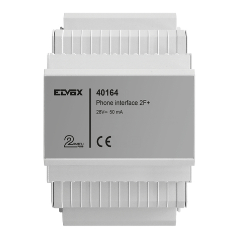
Dispositivo programmabile con 2 relè
Programmable device with 2 relays
Dispositif programmable à 2 relais
Programmierbares Gerät mit 2 Relais
Dispositivo programable con 2 relés
Dispositivo programável com 2 relés
Il manuale istruzioni è scaricabile dal sito www.vimar.com
DESCRIZIONE
L’art. 69RH/L è un dispositivo per impianti DUE FILI. E’ dotato di due relè con contatti normalmente aperti che si possono
comandare separatamente per un tempo impostato in modo indipendente tramite un trimmer. Questo dispositivo si attiva
quando si effettua una chiamata da targa, anche quando il codice di chiamata non corrisponde ad un interno (citofono /
videocitofono).
Per riconoscere se il dispositivo sia stato programmato, osservare il LED luminoso posto sul circuito stampato all’accensione
del dispositivo (vedi L1 gura 1, pag. 8):
LED SPENTO NESSUNA PROGRAMMAZIONE
LED LAMPEGGIANTE PER UN SECONDO ALMENO UNA PROGRAMMAZIONE
DESCRIZIONE MORSETTI E COMPONENTI D’INTERESSE (g. 1)
1, 2, B1, B2) Linea BUS (due coppie di morsetti collegati in parallelo).
1A, 1B) 1° contatto normalmente aperto, carico massimo 3A 230Vca.
2A, 2B) 2° contatto normalmente aperto, carico massimo 3A 230Vca.
TEMPO ATTUAT. 1) Trimmer di regolazione tempo di attivazione 1° contatto
TEMPO ATTUAT. 2) Trimmer di regolazione tempo di attivazione 2° contatto
ID0-ID2) Ponticelli per programmazione
S1) Pulsante per la programmazione/cancellazione numerazione
L1) LED per programmazione/cancellazione numerazione
ABC) ponticelli per la terminazione del BUS.
PROGRAMMAZIONE
La procedura per assegnare un relè a una chiamata è la seguente:
1. LED L1 inizialmente spento e ponticello su ID2 (tab. 1, g. 1 e 2)
2. Posizionare il ponticello su ID2 (Tabella 1, Fig. 1 e 2) per programmare il 1° relé.
3. Tenere premuto il pulsante di programmazione per 2 secondi, no all’accensione del LED L1.
4. A questo punto premere il pulsante della targa o comporre il codice della chiamata associata al relè scelto.
Il LED passa da acceso a lampeggiante.
5. Per confermare premere il pulsante di programmazione. Il LED si spegne e la programmazione è conclusa.
6. Posizionare il ponticello su IDO con ID2 inserito (Tabella 1, Fig. 1 e 2) per programmare il 2° relè.
7. Ripetere i punti 3, 4 e 5 per programmare il 2° relè.
CANCELLAZIONE
Una numerazione precedentemente programmata può essere cancellata nel seguente modo:
1. LED L1 inizialmente spento.
2. Togliere il ponticello da ID2 (g. 1)
3. Posizionare gli altri due ponticelli in dotazione, su ID0 e ID1 in modo da selezionare l’indirizzo della numerazione che si
vuole eliminare (tab. 1, g. 1 e 2)
4. Tenere premuto il pulsante di programmazione per 2 secondi no all’accensione del LED L1. Questo rimane acceso per
un secondo, dopodiché si spegne a conferma dell’avvenuta cancellazione.
5. Ripetere i punti 3 e 4 se si vuole cancellare l’altra programmazione.
2
69RH/L
The instruction manual is downloadable from the site www.vimar.com
DESCRIPTION
Type 69RH/L for DUE FILI installations is a device equipped with two relays with normally open contacts, which can be man-
aged separately for a time preset independently by a trimmer. This device is activated when a call is made by the entrance
panel, even when the call code does not correspond to a internal unit (interphone/ video interphone).
To recognise if the device has been programmed it is enough to see the luminous LED mounted on the printed circuit when
the device is switched on (see L1, Fig. 1, page 8).
LED SWITCHED OFF NO PROGRAMMING
LED FLASHING FOR A SECOND AT LEAST ONE PROGRAMMING
DESCRIPTION OF TERMINALS AND COMPONENTS (g. 1)
1, 2, B1, B2) BUS line (two pairs of terminals connected in parallel).
1A, 1B) 1st normally open contact, maximum load 3A 230Vac.
2A, 2B) 2nd normally open contact, maximum load 3A 230Vac.
ACTIV. TIME 1) Adjustment trimmer for activation time of 1st contact
ACTIV. TIME 2) Adjustment trimmer for activation time of 2nd contact
IDO-ID2) Jumpers for programming
S1) Push-button for group programming/deletion of numbering
L1) LED for group programming/deletion of numbering
ABC) Jumpers for termination of BUS.
PROGRAMMING
The procedure to assign a relay to a call is the following:
1. LED L1 initially switched off and jumper on ID2 (Table 1, Fig. 1 and 2).
2. Set the jumper on ID2 (Table 1, Fig. 1 and 2) to program the 1st relay.
3. Keep the programming push-button pressed for 2 seconds, until the LED L1 switches on.
4. Now press the panel push-button or digit the code of the call associated to the chosen relay.
The led starts ashing.
5. To conrm press the programming push-button. The LED switches off and the programming is accomplished.
6. Set the jumper on IDO with ID2 inserted (Table 1, Fig. 1 and 2) to program the 2nd relay.
7. Repeat the points 3, 4, 5 to program the 2nd relay.
DELETING
A numbering previously programmed can be cancelled in the following way:
1. LED L1 initially off.
2. Remove the jumper from ID2 (Fig. 1)
3. Set the bridge ID0 so as to select the numbering address you want to cancel (Table 1, Fig. 1 and 2)
4. Press and hold the programming key for 2 seconds, until the LED L1 turns on.
This remains lit for one second, after which it turns off to conrm deletion.
5. If you want to cancel the other programming repeat points 3 and 4.
3
69RH/L
Télécharger le manuel d’instructions sur le site www.vimar.com
DESCRIPTION
L’Art. 69RH/L pour installations DUE FILI est un dispositif fourni de deux relais avec contacts normalement ouverts, qui
peuvent être commandés séparément pour un temps programmé de manière indépendante par un trimmer. Ce dispositif
est activé lorsqu’on effectue un appel depuis la plaque de rue, même lorsque le code d’appel ne correspond pas à un poste
interne (poste d’appartement / portier-vidéo).
Pour reconnaître si le dispositif a été programmé il suft d’observer la LED lumineuse placée sur le circuit imprimé à l’allu-
mage du dispositif (voir L1, Fig. 1, page 8).
LED ÉTEINTE AUCUNE PROGRAMMATION
LED CLIGNOTANT POUR UNE SECONDE AU MOINS UNE PROGRAMMATION
DESCRIPTION BORNES ET COMPOSANTS D’INTERET (g. 1)
1, 2, B1, B2) Ligne BUS (deux couples de bornes reliées en parallèle).
1A, 1B) 1er contact normalement ouvert, charge maximum 3A 230Vca.
2A, 2B) 2ème contact normalement ouvert, charge maximum 3A 230Vca.
TEMPS ACTION. 1) Trimmer de réglage temps d’activation 1er contact
TEMPS ACTION. 2) Trimmer de réglage temps d’activation 2ème contact
IDO-ID2) Pontets pour programmation
S1) Bouton pour la programmation/effacement numération
L1) LED pour la programmation/effacement numération
ABC) Pontets pour la terminaison du BUS.
PROGRAMMATION
La procedure pour assigner un relais à un appel est la suivante:
1. La LED L1 est d’abord éteinte et le pontage sur ID2 (Table 1, Fig. 1 et 2).
2. Positionner le pontage sur ID2 (Table 1, Fig. 1 et 2) pour programmer le 1er relais.
3. Maintenir appuyé sur le bouton-poussoir de programmation pour 2 secondes, jusqu’à l’allumage de la LED L1.
4. A ce point appuyer sur le bouton-poussoir de la plaque de rue ou introduire le code de l’appel associé au relais choisi.
La LED commende a clignoter.
5. Pour conrmer appuyer sur le bouton-poussoir de programmation. La LED s’éteint et la programmation est terminée.
6. Positionner le pontage sur IDO avec ID2 inséré (Table 1, Fig. 1 et 2) pour programmer le 2ème relais.
7. Répéter les points 3, 4 et 5 pour programmer le 2ème relais.
EFFACEMENT
Une numérotation précédemment programmer peut être effacée dans la façon suivante :
1. LED L1 initialement éteinte.
2. Enlever le pontet de ID2 (g. 1)
3. Positionner le pontage ID0 de façon à sélectionner l’adresse de la numération qu’on souhaite effacer (Table 1, Fig. 1 et
2).
4. Maintenir le bouton de programmation enfoncé pendant 2 secondes jusqu’à l’allumage de la LED L1. Elle reste allumée
pendant une seconde puis elle s’éteint pour conrmer que l’effacement a été effectué.
5. Si l’on veut effacer l’autre programmation répéter les points 3 et 4.
4
69RH/L
Die Bedienungsanleitung ist auf der Website www.vimar.com zum Download verfügbar
BESCHREIBUNG
Art. 69RH/L für DUE FILI Anlagen ist eine mit zwei Relais ausgerüstete Vorrichtung mit normalerweise offenen Kontakten,
die separat für eine durch einen Trimmer unabhängige programmierte Zeit gesteuert werden können. Diese Vorrichtung
wird bei einem Ruf vom Klingeltableau aktiviert, auch wenn der Rufcode der angerufenen Internsprechstelle (Haustelefon
/ Videohaustelefon) entspricht nicht.
Um zu erkennen ob die Vorrichtung programmiert war, ist es genug die beleuchtete LED, die sich auf der gedrückten Karte
bendet, beim Einschalten der Vorrichtung anzusehen (siehe L1, Abb. 1, Seite 8).
LED AUSGESCHALTET KEINE PROGRAMMIERUNG
LED BLINKEND FÜR EINE SEKUNDE MINDESTENS EINE PROGRAMMIERUNG
BESCHREIBUNG DER KLEMMEN UND DER RELEVANTEN BAUTEILE (Abb. 1)
1, 2, B1, B2) BUS-Leitung (zwei Paar parallelgeschaltete Klemmen).
1A, 1B) 1. Schließerkontakt, max. Kontaktbelastung 3A 230 VAC
2A, 2B) 2. Schließerkontakt, max. Kontaktbelastung 3A 230VAC
AKTIVIERUNGSZEIT 1) Trimmer zur Einstellung der Aktivierungszeit des 1. Kontakts
AKTIVIERUNGSZEIT 2) Trimmer zur Einstellung der Aktivierungszeit des 2. Kontakts
IDO-ID2) Steckbrücken zur Programmierung
S1) Taste für die Programmierung/Löschung von Nummerierung
L1) LED für Programmierung/Löschung von Nummerierung
ABC) Steckbrücken für den Busabschluss.
PROGRAMMIERUNG
Die Prozedur zur Verknüpfung des Relais mit einem Ruf is wie folgend:
1. LED L1 ausgeschaltet und Brücke auf ID2 (Tab. 1, Abb. 1 and 2).
2. Die Brücke auf ID2 setzen (Tabelle 1, Abb. 1 und 2) zur Programmierung des ersten Relais.
3. Die Programmierungstaste für 2 Sekunden bis die Ledbeleuchtung L1 gedrückt halten.
4. Nun die Klingeltableautaste drücken oder den mit dem gewählten Relais verknüpften Rufcode eingeben.
Die LED startet blinken.
5. Zur Bestätigung die Programmierungstaste drücken. Die LED erlischt und die Programmierung beendet.
6. Die Brücke auf IDO (mit ID2 eingesetzt) setzen (Tabelle 1, Abb. 1 und 2) zur Programmierung des zweiten Relais.
7. Die Punkte 3, 4 und 5 zur Programmierung des zweiten Relais wiederholen.
LÖSCHEN
Eine vorkommende programmierte Nummerierung kann auf folgende Weise gelöscht werden
1. LED L1 zunächst ausgeschaltet.
2. Die Steckbrücke von ID2 (Abb. 1) entfernen.
3. Die Brücke ID0 setzen, so dass die Adresse der zu löschende Nummerierung gewählt werden kann (Tab. 1, Abb. 1 and
2).
4. Die Programmiertaste 2 Sekunden lang gedrückt halten, bis die LED L1 aueuchtet. Diese LED bleibt eine Sekunden
lang eingeschaltet, ihr Erlöschen bestätigt die erfolgreiche Löschung der Gruppe.
5. Soll man die andere Programmierung löschen, so wiederholt man die Punkte 3 und 4.
5
69RH/L
El manual de instrucciones se puede descargar en la página web www.vimar.com
DESCRIPCIÓN
El Art. 69RH/L para instalaciones DUE FILI es un dispositivo dotado de dos relés con contactos normalmente abiertos, que
se pueden mandar separadamente por un tiempo programado de manera indipendiente por medio de un trimmer. Este
dispositivo se activa cuando se efectua una llamada desde la placa, también cuando el código de llamada no corresponde
a un aparato interno (teléfono / videoteléfono).
Para reconocer si el dispositivo ha sido programado, es suciente observar el LED luminoso que se encuentra en el cirucito
estampado al momento del encendido del dispositivo (ver L1, Fig. 1, pag 8):
LED APAGADO NINGUNA PROGRAMACIÓN
LED PARPADEANTE POR UN SEGUNDO AL MENOS UNA PROGRAMACIÓN
DESCRIPCIÓN DE LOS BORNES Y DE LOS COMPONENTES DE INTERÉS (g. 1)
1, 2, B1, B2) Línea BUS (dos pares de bornes conectados en paralelo).
1A, 1B) 1° contacto normalmente abierto, carga máxima 3 A 230 Vca.
2A, 2B) 2° contacto normalmente abierto, carga máxima 3 A 230 Vca.
TIEMPO ACT. 1) Trimmer de regulación del tiempo de activación del primer contacto
TIEMPO ACT. 2) Trimmer de regulación del tiempo de activación del segundo contacto
IDO-ID2) Puentes para la programación
S1) Pulsador para programación o borrar los grupos de numeración
L1) Led para la programación o borrar los grupos de numeración
ABC) Puentes para la terminación del BUS.
PROGRAMACIÓN
El procedimento para asignar un relé a una llamada es el siguiente:
1. El LED L1 inicialmente está apagado y el puente en ID2 (Prospecto 1, Fig. 1 y 2).
2. Posicionar el puente en ID2 (Prospecto 1, Fig. 1 y 2) para programar el primer relé.
3. Mantener pulsado el pulsador de programación por 2 segundos hasta el encendido del LED L1.
4. Ahora pulsar el pulsador de la placa o introducir el código de la llamada asociada al relé escogido.
El LED comienza a parpadear
5. Para conrmar pulsar el pulsador de programación. El LED se apaga y la programación es terminada.
6. Posicionar el puente en IDO con ID2 insertado (Prospecto 1, Fig. 1 y 2) para programar el segundo relé.
7. Repetir los puntos 3, 4 y 5 para programar el segundo relé.
BORRADO
Una numeración precedentemente programada puede ser borrada de la manera siguiente:
1. Led L1 inicialmente apagado.
2. Quitar el puente de ID2 (Fig. 1).
3. Posicionar el puente ID0 de manera que se pueda selecionar la dirección de la numeración que se quiere eliminar
(Prospecto 1, Fig. 1 y 2).
4. Mantener accionado el pulsador de programación durante dos segundos o hasta que se encienda el LED L1. El led se
enciende durante un segundo y, luego, se apaga para conrmar que se ha realizado el borrado.
5. Si se quiere cancelar la otra programación, repetir los puntos 3 y 4.
6
69RH/L
É possível descarregar o manual de instruções no site www.vimar.com
DESCRIÇÃO
O Art. 89RH/L para instalações DUE FILI é um dispositivo equipado de dois relés com contactos normalmente abertos, que
podem ser comandados separadamente por un tempo programado de manera independente por meio dum trimmer. Este
dispositivo activa-se quando se efectua uma chamada da botoneira, mesmo quando o código de chamada não corresponde
a um posto interno (telefone / videotelefone).
Para reconhecer se o dispositivo foi programado, es suciente observar o LED luminoso colocado no circuito impresso no
momento do acendimento do dispositivo (ver L1, Fig. 1, pag 8):
LED DESLIGADO NENHUMA PROGRAMAÇÃO
LED CINTILANTE POR UN SEGUNDO PELO MENOS UMA PROGRAMAÇÃO
DESCRIÇÃO DOS BORNES E DOS COMPONENTES (g. 1)
1, 2, B1, B2) Linha BUS (dois pares de bornes ligados em paralelo).
1A, 1B) 1° contacto normalmente aberto, carga máxima 3A 230Vca.
2A, 2B) 2° contacto normalmente aberto, carga máxima 3A 230Vca.
TEMPO ATTUAT. 1) Potenciómetro de regulação do tempo de activação do 1° contacto
TEMPO ATTUAT. 2) Potenciómetro de regulação do tempo de activação do 2° contacto
IDO-ID2) Pontes para .programação
S1) Botão para a programação/eliminação dos grupos de numeração
L1) LED para trabalho e para programação/eliminação dos grupos de numeração
ABC) Pontes para a terminação do BUS.
PROGRAMAÇÃO
O procedimento para assignar um relé a uma chamada é o seguinte:
1. LED L1 inicialmente desligado e ponte em ID2 (Tabela 1, Fig. 1 e 2).
2. Colocar a ponte em ID2 (Tabela 1, Fig. 1 y 2) para programar o primeiro relé.
3. Manter pressionado o botão de programação por 2 segundos até o LED L1 se acender.
4. Neste ponto premir o botão da botoneira ou introduzir o código da chamada associada a um relé escolhido
O LED começa a cintilar.
5. Para conrmar pressionar o botão de programação. O LED desliga-se e a programação está terminada.
6. Colocar a ponte em IDO com ID2 inserido (Tabela 1, Fig. 1 e 2) para programar o segundo relé.
7. Repetir os pontos 3, 4 e 5 para programar o segundo relé.
ELIMINAÇÃO
Uma numeração precedentemente programada pode ser anulada da seguinte maneira:
1. LED L1 inicialmente apagado.
2. Retirar a ponte de ID2 (Fig. 1)
3. Colocar a ponte ID0 de maneira a selecionar a direção da numeração que se quer eliminar (Tabela 1, Fig. 1 e 2).
4. Manter pressionado o botão de programação durante 2 segundos até ao acendimento do LED L1. Este permanece
aceso durante um segundo, após o que se apaga para conrmar a respectiva eliminação.
5. Se se querer anular a outra programação, repetir os pontos 3 et 4.
7
69RH/L
ID2 ID1 ID0692R
1
2
3
4
5
6
7
8
IDENTIFICAZIONE
IDENTIFICATION
IDENTIFIZIERUNG
IDENTIFICACIÓN
IDENTIFICAÇÃO
Ponticello non inserito - Jumper not inserted - Pontage non inséré
Nicht eingesetzte Brücke - Puente no insertado - Ponte não inserido
Ponticello inserito - Jumper inserted - Pontage inséré
Eingesetzte Brücke - Puente insertado - Ponte inserido
TAB. 1
Il 1° relè (morsetti 1A-1B) ripete le chiamate per la numerazione 1.
The 1st Relay (terminals 1A-1B) repeats the calls for numbering 1
Le 1er relais (bornes 1A-1B) répète les appels pour la numération 1.
Das 1° Relais (Klemmen 1A-1B) wiederholt die Rufe für das Nummerierung 1.
El 1er Relé (Bornes 1A-1B) repite las llamadas para la numeración 1.
O 1° relé (Terminais 1A-1B) repite as chamadas para a numeração 1.
Il 2° relè (morsetti 2A-2B) ripete le chiamate per la numerazione 2.
The 2nd Relay (terminals 2A-2B) repeats the calls for numbering 2.
Le 2ème relais (bornes 2A-2B) répète les appels pour la numération 2.
Das 2° Relais (Klemmen 2A-2B) wiederholt die Rufe für das Nummerierung 2.
El 2do relé (Bornes 2A-2B) repite las llamadas para la numeración 2.
O 2° relé (Bornes 2A-2B) repite as llamadas para a numeração 2.
ID0 ID1 ID2692R
1
2
3
4
5
6
7
8
ID0 ID1 ID2
692H
ASSEGNARZIONE GRUPPO 1
ASSEGNARZIONE GRUPPO 2
ASSEGNARZIONE GRUPPO 3
ASSEGNARZIONE GRUPPO 4
CANCELLAZIONE GRUPPO 1
CANCELLAZIONE GRUPPO 2
CANCELLAZIONE GRUPPO 3
CANCELLAZIONE GRUPPO 4
Programmazione
Programming
Programmation
Programmierung
Programación
Programação
Cancellazione
Deletion
Effacement
Löschung
Borrado
Anulação
Assegnazione numerazione 1 - Assigning numbering 1 - Assignation numération 1
Zuweisung Nummerierung 1 - Asignación numeración 1 - Assinação numeração 1
Assegnazione numerazione 2 - Assigning group 2 - Assignation group 2
Zuweisung Nummerierung 2 - Asignación numeración 2 - Assinação numeração 2
Cancellazione numerazione 1 - Deletion numbering 1 - Effacement numération 1
Löschung Nummerierung 1 - Borrado numeración 1 - Anulação numeração 1
Cancellazione numerazione 2 - Deletion numbering 2 - Effacement numération 2
Löschung Nummerierung 2 - Borrado numeración 2 - Anulação numeração 2
{
ID0 ID1 ID2692R
1
2
3
4
5
6
7
8
ID0 ID1 ID2692H
ASSEGNARZIONE GRUPPO 1
ASSEGNARZIONE GRUPPO 2
ASSEGNARZIONE GRUPPO 3
ASSEGNARZIONE GRUPPO 4
CANCELLAZIONE GRUPPO 1
CANCELLAZIONE GRUPPO 2
CANCELLAZIONE GRUPPO 3
CANCELLAZIONE GRUPPO 4
{
8
69RH/L
Assegnazione numerazione 1 - Assigning numbering 1 - Assignation numération 1
Zuweisung Nummerierung 1 - Asignación numeración 1 - Assinação numeração 1
Assegnazione numerazione 2 - Assigning group 2 - Assignation group 2
Zuweisung Nummerierung 2 - Asignación numeración 2 - Assinação numeração 2
Cancellazione numerazione 1 - Deletion numbering 1 - Effacement numération 1
Löschung Nummerierung 1 - Borrado numeración 1 - Anulação numeração 1
Cancellazione numerazione 2 - Deletion numbering 2 - Effacement numération 2
Löschung Nummerierung 2 - Borrado numeración 2 - Anulação numeração 2
A
B
C
1A 1B 2A 2B
L1
S1
12 B1 B2
Tempo attuatore 1
Actuator time 1
Temps actionneur 1
Aktivierungszeit 1
Tiempo actuador 1
Tempo actuador 1
Tempo attuatore 2
Actuator time 2
Temps actionneur 2
Aktivierungszeit 2
Tiempo actuador 2
Tempo actuador 2
IDO
ID1
ID2
Diodo LED
LED diode
Diode LED
LED
Diodo LED
Diodo LED
Terminazione bus A-B-C
(vedi tabella altri schemi)
Termination bus A-B-C
(see table other wiring diagrams)
Termination A-B-C
(voir table d’autres schémas)
Busabschluss A-B-C
(siehe Tabelle andere Schaltpläne)
Terminación bus A-B-C
(ver prospecto de otros esquemas)
Terminação bus A-B-C
(ver tabela de otros esquemas)
Fig. 1
A
B
C
Connettore per assegnazione/cancellazione chiamata
Connector for the call assignation/cancellation.
Connecteur pour l’assignation/effacement de l’appel.
Verbinder für das Rufverknüpfen/Löschen
Conector para la asignación/cancelación de la llamada.
Conector para a assignação/cancelação da chamada.
Fig. 2
Non utilizzare
Not used
Ne pas utiliser
Nicht verwendet
No utilizar
Não utilizar
Pulsante programmazione
Programming push-button
Poussoir programmation
Programmiertaste
Pulsador programación
Botão de programação
9
69RH/L
Legenda per schemi di collegamento - Legenda for wiring diagram
Légende pour schémas de raccordement - Beschriftung für Schalpläne
Leyenda para esquemas de conexionado - Legenda para esquemas de conexionado
Sezione minima conduttori - Minimum conductor section - Section minimale conducteurs
Mindesleitungdurchmesser - Sección mínima conductores - Secção mínima condutores
Morsetti - Terminals - Bornes
Klemmen - Bornes - Terminais
no a 10m - up to 10m - jusqu’à 10m
bis 10m - hasta 10m - até 10m
Serratura elettrica - Electric lock - Gâche électrique
Elektrisches Türschloss - Cerradura eléctrica - Trinco eléctrico 1,5 mm2
Altri - Others - Autres - Andere - Otros - Outros: -, +U, +I, -L(#) 1 mm2
# Gli alimentatori supplementari (Art. 6923, 6582, 6982) devono essere installati il più vicino possibile al dispositivo a cui vengono collegati.
Additional power supply units (type 6923, 6582, 6982) must be installed as near as possible to the device to which they are connected.
Les alimentations supplémentaires (Art. 6923, 6582, 6982) doivent être installées le plus près possible du dispositif auquel elles sont reliées.
Die zusätzlichen Netzgeräte (Art. 6923, 6582, 6982) müssen so nah wie möglich am daran angeschlossenen Gerät installiert werden.
Los alimentadores suplementarios (Art. 6923, 6582, 6982) deben instalarse lo más cerca posible al dispositivo al que se conectan.
Los alimentadores suplementares (Art. 6923, 6582, 6982) devem ser instalados o mais próximo possível do dispositivo ao qual estão ligados.
Impianto videocitofonico semplice “DUE FILI” con relè art. 69RH/L per l’attivazione di due servizi ausiliari da targa.
Simple “DUE FILI” video entrance panel system with relay type 69RH/L for the activation of two auxiliary services
from entrance panel.
Installation de vidéo portier simple “DUE FILI” avec relais Art. 69RH/L pour l’activation de deux services auxiliares
depuis la plaque de rue.
Einfache “DUE FILI” Video-Türsprechanlage mit Relais Art. 69RH/L für die Aktivierung von zwei Diensten aus dem
Klingeltableau.
Instalación de vídeoportero simple “DUE FILI” con relé Art. 69RH/L para la activación de dos servicios auxiliares desde
la placa.
Instalação de videoporteiro simples “DUE FILI” com relé Art. 69RH/L para a activação de dois serviços auxiliares desde
a botoneira.
D - TARGA VIDEO ART. 89F5/C
L - SERRATURA ELETTRICA 12V~ 1A
F - ALIMENTATORE Art. 6922.1
K - PULSANTE PER CHIAMATA FUORIPORTA
P - COMANDO APRIPORTA SUPPLEMENTARE
U - RELÈ ART. 69RH/L
X- Cavo tipo 732H, 732I (Due Fili Twistati)
D - TARGA VIDEO ART. 89F5/C
L - 12V ELECTRIC LOCK
F - POWER SUPPLY Art. 6922.1
K - PUSH-BUTTON FOR OUTDOOR CALL
P - ADDITIONAL LOCK RELEASE CONTROL
U - RELAY ART. 69RH/L
X- Cable type 732H, 732I (Twisted Pair)
D – PLAQUE DUE RUE VIDÉO ART. 89F5/C
L – GÂCHE ÉLECTRIQUE 12V ~
F - ALIMENTATION Art. 6922.1
K – POUSSOIR POUR APPEL PORTE PALIÈRE
P - COMMANDE SUPPLÉMENTAIRE OUVRE PORTE
U - RELAIS ART. 69RH/L
X - Câble Art. 732H, 732I (Deux Fils Torsadés)
D - AUDIO-KLINGELTABLEAU Art. 89F5/C
F - NETZGERÄT Art. 6922.1
L - ELEKTRISCHER TÜRÖFFNER 12V~, max. 1A
K - ETAGENRUFTASTE
P - ZUSÄTZLICHE TÜRÖFFNUNGSSTEUERUNG
U - RELAIS Art. 69RH/L
X- Kabel Art. 732H, 732I (zwei verdrillte Adern)
D - PLACA VIDEO ART. 89F5/C
L - CERRADURA ELÉCTRICA 12V ~ 1A
F - ALIMENTADOR Art. 6922.1
K - PULSADOR SUPLEMENTAR LLAMADA PUERTA
APARTAMIENTO
P - MANDO ABREPUERTA
U - RELÈ ART. 69RH/L
X- Cable Art. 732H, 732I (dos hilos trenzados)
D - BOTONERIA VIDEO ART. 89F5/C
L - TRINCO ELÉCTRICO 12V ~ 1A
F - ALIMENTADOR Art. 6922.1
K - BOTÃO SUPLEMENTARIO PARA CHAMADA NO PA-
TAMAR
P - COMANDO ABREPORTA
U - RELÈ ART. 69RH/L
X- Cabo Art. 732H, 732I (Due Fili Entrançados)
10
69RH/L
4
T2 5
6S
T1 2
1
A
T4 -
+
C
B
VIDEO
T3 6P
1 2
1
E+
FP
E-
2
M
CH
+12
M
V3
4
12
2
3
1
13
CA
M
M
+12V
-L
SR
F1
F2
S-
S+
B2
B1
VLED
X
PA
M
EXT-
EXT+
PRI
B22
1 B1
K
K
K
L
P
D
D
ID2
ID1
ID0
CBA
2B2A
B2B1
1A
1 2
1B
A
C
B
B
A
C
*
*
*
*
Montante - Cable riser - Colonne montante
Steigleitung - Montante - Coluna montante
N° si574
RETE -MAINS
RÉSEAU - NETZ
RED - REDE
1° Contatto N.A. - Carico massimo 3A 230V
1° N.O. contact - Maximum load 3A 230V
1° Contact N.O.- Charge maximum 3A 230V
1. Arbeitskontakt – Max. Last 3A 230V ~
1° Contacto N.A. - Carga máxima 3A 230V ~
Y
X
X- 1° servizio relè Art. 69RH/L
1° Relay service Art. 69RH/L
1° Service relais Art. 69RH/L
1° Relaisdienst Art. 69RH/L
1° Servicio relé Art. 69RH/L
1° Serviço relé Art. 69RH/L
Y- 2° servizio relè Art. 69RH/L
2° Relay service Art. 69RH/L
2° Service relais Art. 69RH/L
2° Relaisdienst Art. 69RH/L
2° Servicio relé Art. 69HR/L
2° Serviço relé Art. 69HR/L
U
F
X
MONITOR
Art. 6029+6209+692P+6145
Art. 6029/C+6209+692P+6145
MONITOR
Art. 6329
Art. 6329/C
MONITOR
Art. 6621
Art. 6611
Art. 662C
Art. 661C
Art. 6721
Art. 6711
Art. 6xxx/F
X
X
X
X
X
4
T2 5
6S
T1 2
1
A
T4 -
+
C
B
VIDEO
T3 6P
1 2
1
E+
FP
E-
2
M
CH
+12
M
V3
4
12
2
3
1
13
CA
M
M
+12V
-L
SR
F1
F2
S-
S+
B2
B1
VLED
X
PA
M
EXT-
EXT+
PRI
B22
1 B1
K
K
K
L
P
D
D
ID2
ID1
ID0
CBA
2B2A
B2B1
1A
1 2
1B
A
C
B
B
A
C
*
*
*
*
2° Contatto N.A. - Carico massimo 3A 230V
2° N.O. Contact - Maximum load 3A 230V
2° Contact N.O. - Charge maximum 3A 230V
2. Arbeitskontakt – Max. Last 3A 230V ~
2° Contacto N.A. - Carga máxima 3A 230V ~
2° Contacto N.A.- Carga máxima 3A 230V ~
11
69RH/L
*
TERMINAÇÃO BUS
Esta nota aplica-se a todos os dispositivos da tecno-
logia Due Fili Plus dotados do “conector ou dip-
switch de terminação BUS” identificado pela marca
serigráfica “ABC” e assinalado nos esquemas de
ligação com
*
.
Para a adaptação correcta da linha deve fazer-se a
configuração de acordo com a seguinte regra:
Mantenha a posição “A” se o BUS entrar e sair do
dispositivo;
Desloque-se para a posição “B” (se for um cabo
Elvox) ou para a posição “C” (se for um cabo “CAT5”
com os pares entrançados acoplados), se a linha do
BUS “terminar” no próprio dispositivo.
“A” = NENHUMA TERMINAÇÃO
“B” = TERMINAÇÃO 100 ohm
“C” = TERMINAÇÃO 50 ohm
INSTALAÇÕES COM DISTRIBUIDOR PASSIVO
692D
(versão com “calha DIN”)
Utilize SEMPRE a saída 1 do distribuidor art. 692D
(a única que não tem a ponte de terminação). Para
a terminação do art. 692D: Se as saídas “OUT”, “2”,
“3” ou “4” não forem utilizadas, MANTENHA a ponte
no conector “TOUT”, “T2”, “T3” ou “T4”. Por defeito,
a ponte “TOUT” está na posição “100” (cabo Elvox),
coloque-o em “50” apenas se utilizar um cabo CAT5
com os pares de fios entrelaçados acoplados.
INSTALAÇÕES COM DISTRIBUIDOR ACTIVO
692D/2.
A ponte de terminação deve ser posicionada em “B”
(para o cabo Elvox) ou em “C” (para o cabo CAT5
com pares de fios entrelaçados acoplados) SE E
APENAS SE o BUS terminar no próprio dispositivo.
Deve ser deixado em “A” se se fizer o “entra/sai” uti-
lizando os bornes 1-2 do 692D/2.
*
TERMINACIÓN DEL BUS
Esta nota se aplica a todos los dispositivos con tec-
nología Due Fili Plus provistos de “conector o con-
mutador DIP de terminación BUS” identificado por la
serigrafía “ABC” y marcado en los esquemas de
conexión con
*
.
Para la correcta adaptación de la línea hay que re-
alizar la configuración según la regla siguiente:
Mantener la posición “A” si el BUS entra y sale del
dispositivo;
Desplazar a la posición “B” (si el cable es Elvox) o
bien a la posición “C” (si el cable es “CAT5” con los
pares acoplados), si la línea del BUS “termina” en el
propio dispositivo.
“A” = Ninguna TERMINACIÓN
“B” = TERMINACIÓN 100 ohmios
“C” = TERMINACIÓN 50 ohmios
EQUIPOS CON DISTRIBUIDOR PASIVO 692D
(versión con “riel DIN”)
Utilice SIEMPRE la salida 1 del distribuidor Art.
692D (la única que no tiene el conector puente de
terminación).
Para la terminación del Art. 692D: Si no se utilizan
las salidas “OUT”, “2”, “3” o “4”, mantenga el conector
puente en el conector “TOUT”, “T2”, “T3” o “T4” . Por
defecto, el conector puente “TOUT” está en posición
“100” (cable Elvox): colóquelo en “50” solo si se utiliza
un cable CAT5 con los pares acoplados.
EQUIPOS CON DISTRIBUIDOR ACTIVO 692D/2.
El conector puente de terminación debe posicionarse
en “B” (para el cable Elvox) o en “C” (para el cable
CAT5 con pares acoplados) EXCLUSIVAMENTE
SI el BUS termina en el dispositivo. Debe dejarse
en “A” si se utilizan los bornes 1-2 del 692D/2 para
entrada-salida.
*
TERMINAZIONE BUS
Questa nota si applica a tutti i dispositivi della tecno-
logia Due Fili Plus dotati del “connettore o dip-switch
di terminazione BUS” identicato dalla scritta serigra-
ca “ABC” e segnalato sugli schemi di collegamento
con
*
.
Per il corretto adattamento della linea va effettuato il
settaggio secondo la seguente regola:
Mantenere posizione “A” se il BUS entra ed esce dal
dispositivo;
Spostare in posizione “B” (se cavo Elvox) oppure in
posizione “C” (se cavo “CAT5” con i doppini accop-
piati), se la linea del BUS “termina” nel dispositivo
stesso.
“A” = NESSUNA TERMINAZIONE
“B” = TERMINAZIONE 100 ohm
“C” = TERMINAZIONE 50 ohm
IMPIANTI CON DISTRIBUTORE PASSIVO 692D
(versione “barra din”)
Utilizzare SEMPRE l’uscita 1 del distributore art.692D
(l’unica che non ha il ponticello di terminazione). Per
la terminazione dell’art.692D:
Se le uscite “OUT”, “2”, “3” o “4” non vengono uti-
lizzate, MANTENERE il ponticello sul connettore
“TOUT”, “T2”, “T3” o “T4” . Il ponticello “TOUT” di
default è in posizione “100” (cavo Elvox), posizionarlo
su “50” solo se si utilizza un cavo CAT5 con i doppini
accoppiati.
IMPIANTI CON DISTRIBUTORE ATTIVO 692D/2.
Il ponticello di terminazione va posizionato su “B”
(per cavo Elvox) o su “C” (per cavo CAT5 con dop-
pini accoppiati) SE E SOLO SE il BUS termina sul
dispositivo stesso. Va lasciato su “A” se si effettua
l’entra-esci utilizzando i morsetti 1-2 del 692D/2.
*
BUS TERMINATION
This note applies to all devices with Due Fili Plus
technology equipped with “BUS termination connec-
tor or dip-switch”, which is identified by the screen-
printed letters “ABC” and marked on the wiring
diagrams with
*
.
For correct adaptation of the line, make the setting
according to the following rule:
Maintain position “A” if the BUS enters and exits from
the device;
Move to position “B” (if Elvox cable) or to position “C”
(if CAT5 twisted pair cable) if the BUS line terminates
in the device itself.
“A” = NO TERMINATION
“B” = TERMINATION 100 ohm
“C” = TERMINATION 50 ohm
INSTALLATIONS WITH PASSIVE DISTRIBUTOR
692D
(DIN rail version)
ALWAYS use output 1 on distributor type 692D (the
only one that has no termination jumper).
For termination of type 692D: If outputs “OUT”, “2”,
“3” or “4” are not used, KEEP the jumper on the
“TOUT”, “T2”, “T3” or “T4” connector. The default
“TOUT” connector is in the “100” position (Elvox
cable), position it to “50” only if using a CAT5 twisted
pair cable.
INSTALLATIONS WITH ACTIVE DISTRIBUTOR
692D/2.
The termination jumper must be positioned on “B” (for
Elvox cable) or on “C” (for CAT5 twisted pair cable)
IF AND ONLY IF the BUS terminates at the device
itself. It must be left on “A” if effecting entry-exit using
terminals 1-2 on 692D/2.
*
TERMINAISON BUS
Cette remarque concerne tous les dispositifs de la
technologie Due Fili Plus dotés du « connecteur ou
du commutateur de terminaison du Bus » identifié par
« ABC » et indiqué sur les schémas par un
*
.
Pour l’adaptation correcte de la ligne, procéder au
réglage selon la règle ci-après :
Conserver la position « A » si le Bus entre et sort
du dispositif ;
Déplacer sur la position « B » (câble Elvox) ou sur la
position « C » (câble « CAT5 » à paires torsadées),
si la ligne du Bus « arrive » au dispositif.
“A” = AUCUNE TERMINAISON
“B” = TERMINAISON 100 ohm
“C” = TERMINAISON 50 ohm
INSTALLATIONS AVEC DISTRIBUTEUR PASSIF
692D
(version “rail DIN”)
Utiliser TOUJOURS la sortie 1 du distributeur art.
692D (la seule qui n’a pas le pontet de terminaison).
Pour la terminaison de l’art. 692D : si toutes les sor-
ties “OUT”, “2”, “3” ou “4” ne sont pas utilisées, MAIN-
TENIR le pontet sur le connecteur “TOUT”, “T2”, “T3”
ou “T4”. Le pontet “TOUT” par défaut est en position
“100” (câble Elvox), le positionner sur “50” unique-
ment si l’on utilise un câble CAT5 à paires torsadées.
INSTALLATIONS AVEC DISTRIBUTEUR ACTIF
692D/2.
Le pontet de terminaison doit être positionné sur “B”
(pour câble Elvox) ou sur “C” (pour câble CAT5 avec
paires torsadées) UNIQUEMENT SI le BUS se ter-
mine sur ledit dispositif. Il doit être laissé sur “A” si
l’on effectue l’entrée-sortie en utilisant les bornes 1-2
de l’art. 692D/2.
*
BUSTERMINIERUNG
Dieser Hinweis gilt für alle Geräte der Technologie
Due Fili Plus mit “Steckverbinder oder DIP-Schalter
der Busterminierung”, der mit dem Aufdruck “ABC”
markiert und der auf den Anschlussplänen mit
*
gekennzeichnet ist.
Für die korrekte Anpassung der Leitung ist die Ein-
stellung gemäß der folgender Regel vorzunehmen:
Die Position “A” beibehalten, wenn der BUS vom
Gerät ein- und wieder austritt;
Auf Position “B” (Elvox-Kabel) bzw. in Position “C”
(“CAT-5-Kabel” mit gepaarten Doppeladern), verset-
zen, wenn die Busleitung im Gerät selbst “terminiert”.
“A” = KEINE TERMINIERUNG
“B” = TERMINIERUNG 100 Ohm
“C” = TERMINIERUNG 50 Ohm
ANLAGEN MIT PASSIVVERTEILER ART.692D
(Version für “DIN-Schiene”)
IMMER den Ausgang 1 des Verteilers Art.692D
verwenden (der einzige ohne Terminierungs-Steck-
brücke). Für die Terminierung von Art.692D: Wenn
die Ausgänge “OUT”, “2”, “3” oder “4” nicht benutzt
werden, die Steckbrücke am Steckverbinder “TOUT”,
“T2”, “T3” bzw. “T4” EINGESETZT LASSEN. Die
Standardposition der Steckbrücke “TOUT” ist “100”
(Elvox-Kabel), nur bei Verwendung eines Cat-5-Ka-
bels auf “50” setzen.
ANLAGEN MIT AKTIVVERTEILER ART. 692D/2.
NUR WENN DER BUS im Gerät selbst endet,
muss die Terminierungs-Steckbrücke in Position
“B” (Elvox-Kabel) bzw. in “C” (Cat-5-Kabel) einge-
setzt werden. Bei Ein-/Austritt an den Klemmen 1-2
des Art. 692D/2 muss sie in Position “A” gelassen
werden.
12
69RH/L
Note:
13
69RH/L
Il manuale istruzioni è scaricabile dal
sito www.vimar.com
Regole di installazione
L’installazione deve essere
effettuata da personale qualicato
con l’osservanza delle disposizioni
regolanti l’installazione del materiale
elettrico in vigore nel paese dove i
prodotti sono installati.
Conformità normativa
Direttiva EMC
Norme EN 61000-6-1 e EN 61000-
6-3.
The instruction manual is
downloadable from the site www.
vimar.com
Installation rules
Installation should be carried out by
qualied personnel in compliance with
the current regulations regarding the
installation of electrical equipment in
the country where the products are
installed.
Conformity
EMC directive
Standards EN 61000-6-1 and EN
61000-6-3.
Télécharger le manuel d’instructions
sur le site www.vimar.com
Règles d’installation
L’installation doit etre conee a des
personnel qualies et executee
conformement aux dispositions qui
regissent l’installation du materiel
electrique en vigueur dans le pays
concerne.
Conformité aux normes
Directive EMC
Normes EN 61000-6-1 et EN 61000-
6-3.
RAEE - Informazione
agli utilizzatori
Il simbolo del cassonetto
barrato riportato
sull’apparecchiatura o sulla sua
confezione indica che il prodotto alla
ne della propria vita utile deve essere
raccolto separatamente dagli altri riuti.
L’utente dovrà, pertanto, conferire
l’apparecchiatura giunta a ne vita
agli idonei centri comunali di raccolta
differenziata dei riuti elettrotecnici ed
elettronici. In alternativa alla gestione
autonoma, è possibile consegnare
gratuitamente l’apparecchiatura che
si desidera smaltire al distributore,
al momento dell’acquisto di una
nuova apparecchiatura di tipo
equivalente. Presso i distributori di
prodotti elettronici con supercie di
vendita di almeno 400 m2è inoltre
possibile consegnare gratuitamente,
senza obbligo di acquisto, i prodotti
elettronici da smaltire con dimensioni
inferiori a 25 cm. L’adeguata raccolta
differenziata per l’avvio successivo
dell’apparecchiatura dismessa
al riciclaggio, al trattamento e
allo smaltimento ambientalmente
compatibile contribuisce ad evitare
possibili effetti negativi sull’ambiente e
sulla salute e favorisce il reimpiego e/o
riciclo dei materiali di cui è composta
l’apparecchiatura.
WEEE - Information
for users
If the crossed-out bin symbol
appears on the equipment or
packaging, this means the product
must not be included with other general
waste at the end of its working life.
The user must take the worn product
to a sorted waste center, or return it
to the retailer when purchasing a new
one. Products for disposal can be
consigned free of charge (without any
new purchase obligation) to retailers
with a sales area of at least 400m2,
if they measure less than 25cm. An
efcient sorted waste collection for
the environmentally friendly disposal
of the used device, or its subsequent
recycling, helps avoid the potential
negative effects on the environment
and people’s health, and encourages
the re-use and/or recycling of the
construction materials.
DEEE - Informations
pour les utilisateurs
Le symbole du caisson barré, là
où il est reporté sur l’appareil ou
l’emballage, indique que le produit en
n de vie doit être collecté séparément
des autres déchets. Au terme de la
durée de vie du produit, l’utilisateur
devra se charger de le remettre à un
centre de collecte séparée ou bien au
revendeur lors de l’achat d’un nouveau
produit. Il est possible de remettre
gratuitement, sans obligation d’achat,
les produits à éliminer de dimensions
inférieures à 25 cm aux revendeurs
dont la surface de vente est d’au moins
400 m2. La collecte séparée appropriée
pour l’envoi successif de l’appareil en
n de vie au recyclage, au traitement
et à l’élimination dans le respect de
l’environnement contribue à éviter les
effets négatifs sur l’environnement
et sur la santé et favorise le réemploi
et/ou le recyclage des matériaux dont
l’appareil est composé.
14
69RH/L
Die Bedienungsanleitung ist auf
der Website www.vimar.com zum
Download verfügbar
Installationsvorschriften
Die Installation muss durch
Fachpersonal gema. den im
Anwendungsland des Gerats
geltenden Vorschriften zur Installation
elektrischen Materials erfolgen.
Normkonformität
EMC-Richtlinie
Normen DIN EN 61000-6-1 und EN
61000-6-3.
El manual de instrucciones se puede
descargar en la página web www.
vimar.com
Normas de instalación
La instalacion debe ser realizada por
personal cualicado cumpliendo con
las disposiciones en vigor que regulan
el montaje del material electrico en el
pais donde se instalen los productos.
Conformidad normativa
Directiva EMC
Normas EN 61000-6-1 y EN 61000-
6-3.
É possível descarregar o manual de
instruções no site www.vimar.com
Regras de instalação
A instalação deve ser efetuada por
pessoal qualicado de acordo com as
disposições que regulam a instalação
de material elétrico, vigentes no País
em que os produtos são instalados.
Cumprimento de
regulamentação
Directiva EMC
Normas EN 61000-6-1 e EN 61000-
6-3.
Elektro- und
Elektronik-Altgeräte -
Informationen für die
Nutzer
Das Symbol der durchgestrichenen
Mülltonne auf dem Gerät oder
seiner Verpackung weist darauf hin,
dass das Produkt am Ende seiner
Nutzungsdauer getrennt von den
anderen Abfällen zu entsorgen ist.
Nach Ende der Nutzungsdauer
obliegt es dem Nutzer, das Produkt
in einer geeigneten Sammelstelle
für getrennte Müllentsorgung zu
deponieren oder es dem Händler
bei Ankauf eines neuen Produkts zu
übergeben. Bei Händlern mit einer
Verkaufsäche von mindestens
400 m2können zu entsorgende
Produkte mit Abmessungen
unter 25 cm kostenlos und ohne
Kaufzwang abgegeben werden. Die
angemessene Mülltrennung für das
dem Recycling, der Behandlung und
der umweltverträglichen Entsorgung
zugeführten Gerätes trägt dazu bei,
mögliche negative Auswirkungen
auf die Umwelt und die Gesundheit
zu vermeiden und begünstigt den
Wiedereinsatz und/oder das Recyceln
der Materialien, aus denen das Gerat
besteht.
RAEE - Información
para los usuarios
El símbolo del contenedor
tachado, cuando se indica en
el aparato o en el envase, indica que
el producto, al nal de su vida útil, se
debe recoger separado de los demás
residuos. Al nal del uso, el usuario
deberá encargarse de llevar el producto
a un centro de recogida selectiva
adecuado o devolvérselo al vendedor
con ocasión de la compra de un nuevo
producto. En las tiendas con una
supercie de venta de al menos 400
m2, es posible entregar gratuitamente,
sin obligación de compra, los
productos que se deben eliminar con
unas dimensiones inferiores a 25 cm.
La recogida selectiva adecuada para
proceder posteriormente al reciclaje,
al tratamiento y a la eliminación del
aparato de manera compatible con el
medio ambiente contribuye a evitar
posibles efectos negativos en el medio
ambiente y en la salud y favorece
la reutilización y/o el reciclaje de los
materiales de los que se compone el
aparato.
REEE - Informação
dos utilizadores
O símbolo do contentor
de lixo barrado com uma
cruz, axado no equipamento ou na
embalagem, indica que o produto, no
m da sua vida útil, deve ser recolhido
separadamente dos outros resíduos.
No nal da utilização, o utilizador
deverá encarregar-se de entregar
o produto num centro de recolha
seletiva adequado ou de devolvê-lo
ao revendedor no ato da aquisição
de um novo produto. Nas superfícies
de venda com, pelo menos, 400 m2, é
possível entregar gratuitamente, sem
obrigação de compra, os produtos a
eliminar com dimensão inferior a 25
cm. A adequada recolha diferenciada
para dar início à reciclagem,
ao tratamento e à eliminação
ambientalmente compatível, contribui
para evitar possíveis efeitos negativos
ao ambiente e à saúde e favorece
a reutilização e/ou reciclagem dos
materiais que constituem o aparelho.
15
69RH/L
Viale Vicenza, 14
36063 Marostica VI - Italy
www.vimar.com
S6I.69R.HL0 06 1810

This manual suits for next models

1

Other Vimar Intercom System manuals

Vimar ELVOX 7558 Tab Free 4.3 User manual

Vimar

Vimar ELVOX 7558 Tab Free 4.3 User manual

Vimar Elvox 1282 Assembly instructions

Vimar

Vimar Elvox 1282 Assembly instructions

Vimar ELVOX K40505.R User guide

Vimar

Vimar ELVOX K40505.R User guide

Vimar ELVOX 692D Assembly instructions

Vimar

Vimar ELVOX 692D Assembly instructions

Vimar ELVOX Petrarca 6140 User manual

Vimar

Vimar ELVOX Petrarca 6140 User manual

Vimar ELVOX TAB 40507 User manual

Vimar

Vimar ELVOX TAB 40507 User manual

Vimar ELVOX PIXEL UP: 40415.S User guide

Vimar

Vimar ELVOX PIXEL UP: 40415.S User guide

Vimar Elvox K40900 User manual

Vimar

Vimar Elvox K40900 User manual

Vimar ELVOX TAB Series User manual

Vimar

Vimar ELVOX TAB Series User manual

Vimar ELVOX 8000 Series Assembly instructions

Vimar

Vimar ELVOX 8000 Series Assembly instructions

Vimar ELVOX 13F1 Assembly instructions

Vimar

Vimar ELVOX 13F1 Assembly instructions

Vimar ELVOX Videocitofonia 7539 User manual

Vimar

Vimar ELVOX Videocitofonia 7539 User manual

Vimar ELVOX 930D User manual

Vimar

Vimar ELVOX 930D User manual

Vimar ELVOX K40945 User manual

Vimar

Vimar ELVOX K40945 User manual

Vimar Elvox 4000/A01 Assembly instructions

Vimar

Vimar Elvox 4000/A01 Assembly instructions

Vimar K40910 User manual

Vimar

Vimar K40910 User manual

Vimar 62IG Assembly instructions

Vimar

Vimar 62IG Assembly instructions

Vimar ELVOX 1283 Assembly instructions

Vimar

Vimar ELVOX 1283 Assembly instructions

Vimar Elvox 0170/101 Assembly instructions

Vimar

Vimar Elvox 0170/101 Assembly instructions

Vimar ELVOX 69RH Assembly instructions

Vimar

Vimar ELVOX 69RH Assembly instructions

Vimar Elvox 875G/S Assembly instructions

Vimar

Vimar Elvox 875G/S Assembly instructions

Vimar Elvox Due Fili Plus 7549/M User guide

Vimar

Vimar Elvox Due Fili Plus 7549/M User guide

Vimar K40517G.01 User guide

Vimar

Vimar K40517G.01 User guide

Vimar ELVOX K40505/M User manual

Vimar

Vimar ELVOX K40505/M User manual

Popular Intercom System manuals by other brands

FingerTec i-Kiosk 100 Plus installation guide

FingerTec

FingerTec i-Kiosk 100 Plus installation guide

urmet domus 956 Installation and instruction manual

urmet domus

urmet domus 956 Installation and instruction manual

Yale ENTR S quick guide

Yale

Yale ENTR S quick guide

Bticino 346310 manual

Bticino

Bticino 346310 manual

USG EquiCoach 4 Quick setup guide

USG

USG EquiCoach 4 Quick setup guide

Aiphone JK-1MED Installation and operation manual

Aiphone

Aiphone JK-1MED Installation and operation manual

ABB H81381P Series product manual

ABB

ABB H81381P Series product manual

ProTalk PT-Door01 user guide

ProTalk

ProTalk PT-Door01 user guide

Konig SEC-PH380 manual

Konig

Konig SEC-PH380 manual

Honeywell VisioCam RCWL8000A Installation and use

Honeywell

Honeywell VisioCam RCWL8000A Installation and use

Extel MOMBO Ed. 12 - 2014 V1 Installation and user guide

Extel

Extel MOMBO Ed. 12 - 2014 V1 Installation and user guide

Ultra Secure ULTRACOM 3 manual

Ultra Secure

Ultra Secure ULTRACOM 3 manual

Talkaphone ETP-120 Series Installation & operation manual

Talkaphone

Talkaphone ETP-120 Series Installation & operation manual

1 BY ONE Easy Chime OUKQH-0761 instruction manual

1 BY ONE

1 BY ONE Easy Chime OUKQH-0761 instruction manual

urmet domus 1083 Configuration Booklet

urmet domus

urmet domus 1083 Configuration Booklet

Microsound MD 602 instruction manual

Microsound

Microsound MD 602 instruction manual

THOMSON 513127 quick start guide

THOMSON

THOMSON 513127 quick start guide

Olympia VDB 824YA manual

Olympia

Olympia VDB 824YA manual

manuals.online logo
manuals.online logoBrands
  • About & Mission
  • Contact us
  • Privacy Policy
  • Terms and Conditions

Copyright 2025 Manuals.Online. All Rights Reserved.