3
904107 REV C 4/13/15, INST 69 FIREBIRD w/o AC CNTRL PNL PG 3 OF 17
No. Qty. Part No. Description
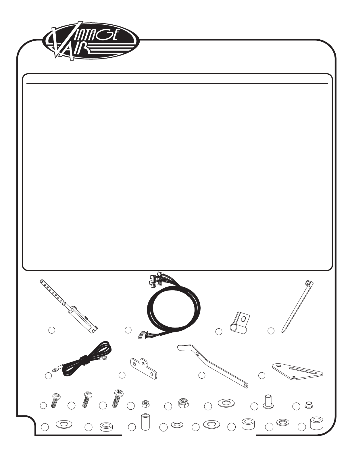
Packing List: 1969 Firebird
Control Panel Conversion Kit (474164)
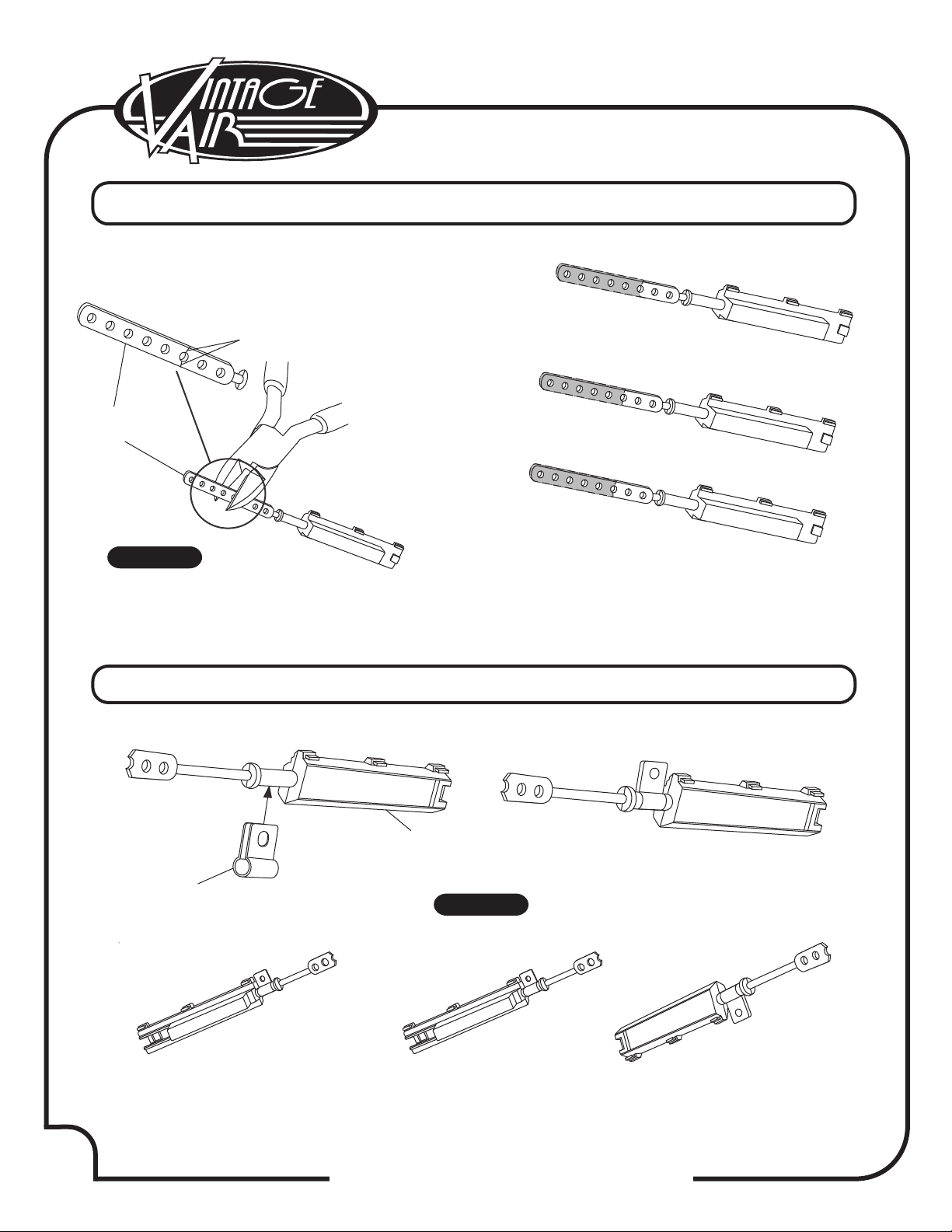
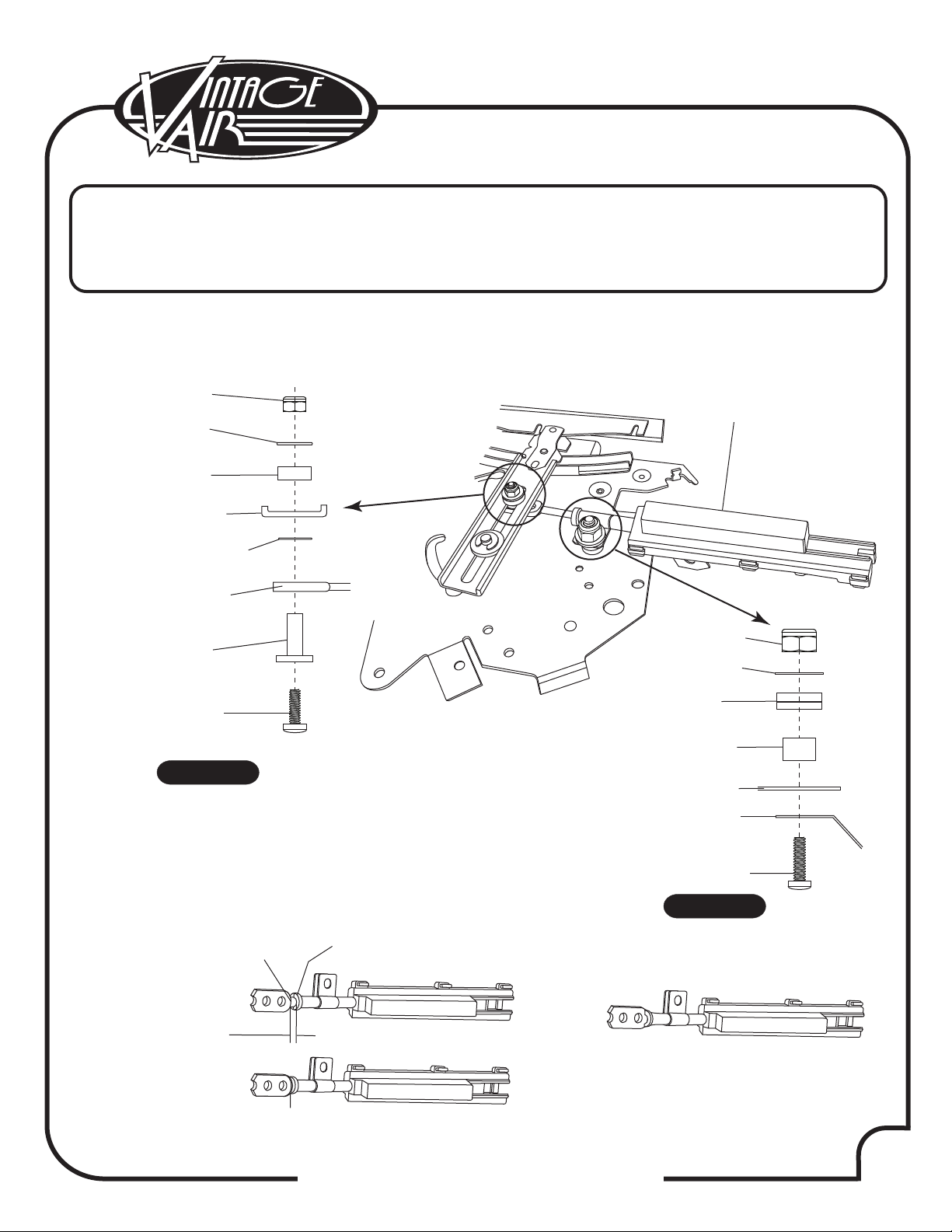
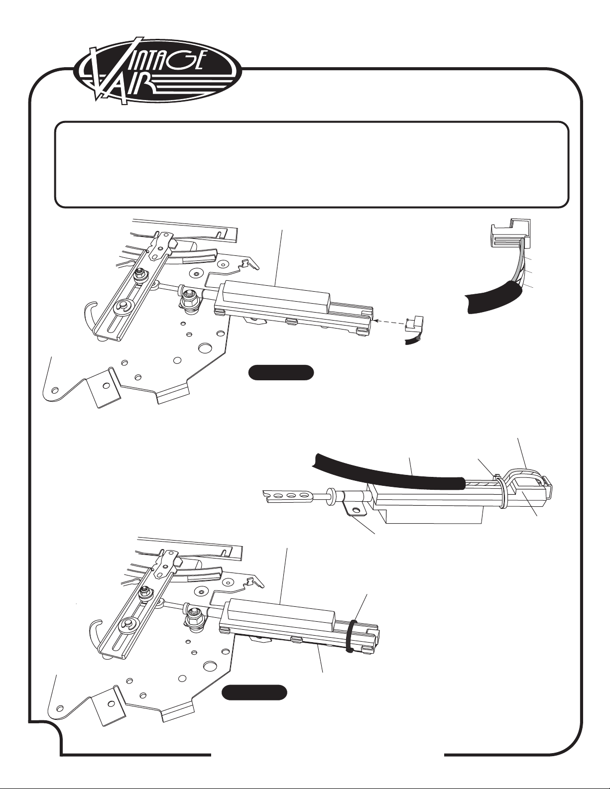
Slide Pot Assembly
Gen IV Universal Control Harness
Slide Pot Clamp
4” Tie Wrap
Ground Wire
69 Firebird Blower Switch Pivot Bracket
69 Firebird Blower Switch Lever
69 Firebird wo A/C Heat/Cool Control Bracket
4-40 X 3/8” PH Pan Head Screw
4-40 X 5/8” PH Pan Head Screw
8-32 X 3/4” PH Pan Head Screw
4-40 Nyloc Nut
8-32 Nyloc Nut
#8 Flat Washer
1/8” Nylon Insert
Nylon Bushing
1/16” Nylon Flat Washer
1/8” Nylon Flat Washer
.128 ID/.198 ID x.313 OD x.375 L Nylon Spacer
SAE Flat Washer 3/16” X .500
1/16” Nylon Spacer/ Washer
.166 ID x .375 OD x .250 L Nylon Flat Washer
.140 ID x .250 OD x .065 L Nylon Flat Washer
.188 ID x .375 OD x .188 L Nylon Flat Washer
112002-SUA
232002-VUA
491010-VUR
21301-VUP
231520
644014
644015
644016
18413-VUB
18400-VUB
18113-PSR
18412-VUB
18602-NSR
18657-JSS
49700-VUI
49701-VUI
49704-VUI
49705-VUI
180041-SSR
18123-VUB
186009-WSR
180385
180383
180384
3
1
3
5
1
1
1
1
3
3
2
6
2
4
3
1
3
3
1
3
1
1
2
1
1.
2.
3.
4.
5.
6.
7.
8.
9.
10.
11.
12.
13.
14.
15.
16.
17.
18.
19.
20.
21.
22.
23.
24.
** Before beginning installation, open all packages and check contents of shipment.
Please report any shortages directly to Vintage Air within 15 days. After 15 days,
Vintage Air will not be responsible for missing or damaged items.
2
6
4
57
13
8
9 10 11 12 13 14 15 16
17 18 19 20 21 22 23 24