manuals.online logo
Brands
  1. Home
  2. •
  3. Brands
  4. •
  5. Viro
  6. •
  7. Lock
  8. •
  9. Viro 4259 Quick start guide

Viro 4259 Quick start guide

43
42
40
57 28,5
40
GB
I
GB
E
I
F
E
I
GB
F
E
F
B
B
B
B
A
A
A
A
Dima di foratura
Drilling template
Gabarit de perçage
Plantilla de taladrado
A F
E
C
AA
A
D
Lato esterno
External side
Côté extérieur
Lado externo
Lato interno
Internal side
Côté intérieur
Lado interno
4X
1X
A
F
C
1X 1X
4X
B
E
Accessories included
1X
D
Accessoires fournis
Accesorios suministrados
Accessori in dotazione
R
www.viro.it
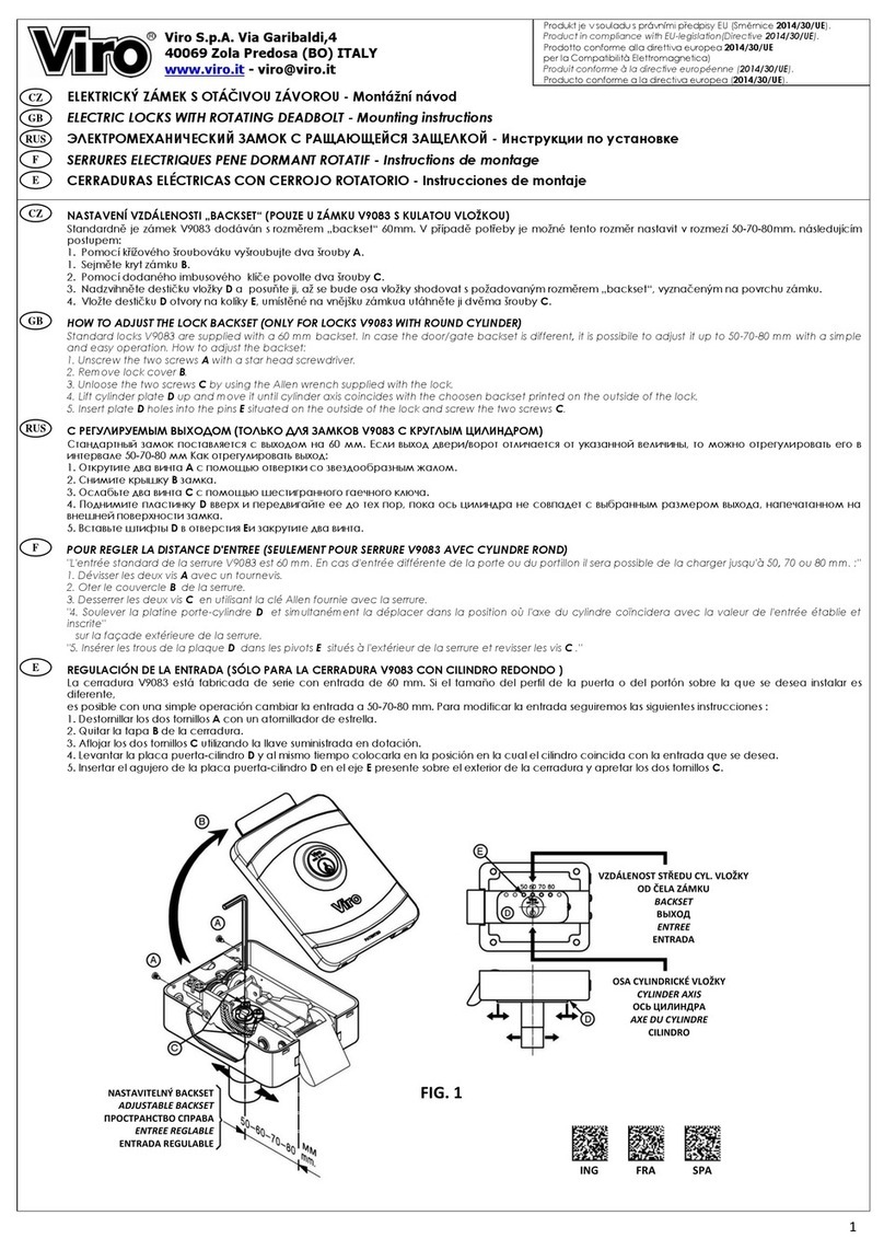
CASSETTA PORTACHIAVI A COMBINAZIONE DA MURO - Installazione ed uso
WALL KEY COMBINATION BOX - Installation and use
INSTALLAZIONE A MURO
Posizionare la dima dove si desidera installare la cassetta;
1.
Forare il muro con una punta
5,5 mm ed inserire i tasselli
B
;
2.
Fissare con le viti
A
fornite in dotazione.
3.
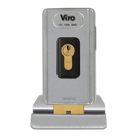
INSTALLAZIONE SU PORTA (solo per ARTT. 4259, 4259.7 E 4259.L.7)
É possibile installare la cassetta sulla porta d'ingresso, sostituendola allo spioncino.
Smontare lo spioncino;
1.
Posizionare la cassetta facendo coincidere il foro centrale con il foro dello
2.
spioncino;
Fissare con la vite
F
che verrà fermata con le rondelle
C
e
D
e il dado
E
nel lato
3.
interno della porta;
Completare il fissaggio con le viti
A
in dotazione.
4.
ART. 4259.S.7
ARTT. 4259-4259.7
ART. 4259.L.7
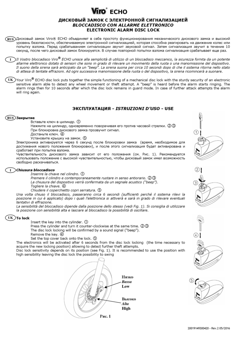
DOOR INSTALLATION (only for ITEM 4259, 4259.7 and 4259.L.7)
It is possible to install the box on the front door, replacing the peephole.
Remove the peephole;
1.
Place the box by making the central hole coincide with the peephole hole;
2.
Fix with screw
F
that will be stopped with washer
C
and
D
and nut
E
in the
3.
inner side of the door;
Complete fixing with the supplied screws
A
.
4.
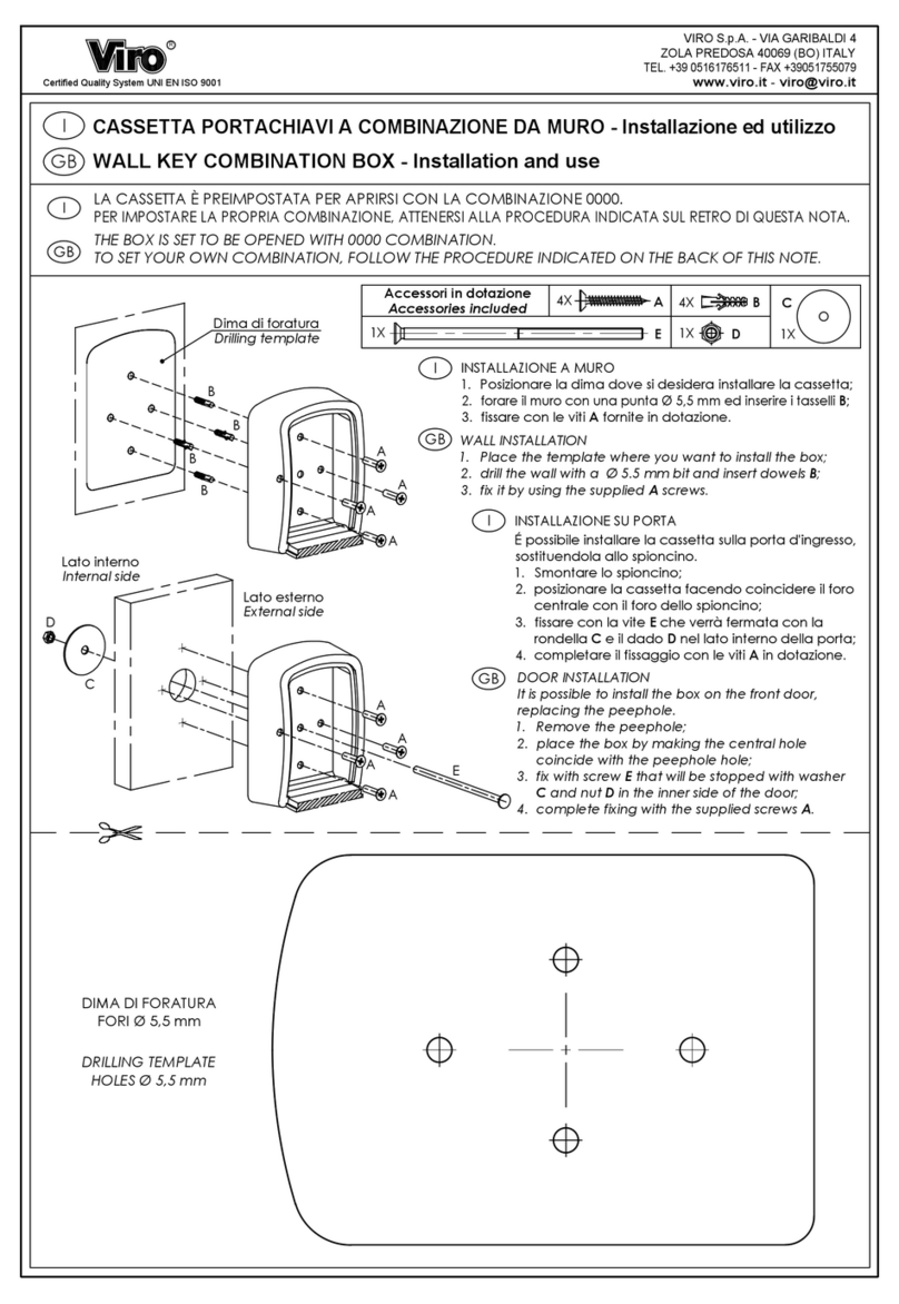
WALL INSTALLATION
1. Place the template where you want to install the box;
2. Drill the wall with a
5.5 mm bit and insert dowels
B
;
3. Fix it by using the supplied
A
screws.
DIMA DI FORATURA
FORI
5,5 mm
DIMENSIONI IN mm
DRILLING TEMPLATE
HOLES
5.5 mm
DIMENSIONS IN mm
CAJITA PORTA LLAVES CON COMBINACIÓN PARA PARED - Instalación y uso
INSTALLATION AU MUR
1. Positionner le gabarit à l'endroit où vous souhaitez installer le coffret;
2. Percer le mur avec une mèche de Ø 5,5 mm et insérer les chevilles
B
;
3. Fixer avec les vis
A
fournies.
INSTALACIÓN EN PUERTA (solo para ARTT. 4259, 4259.7 y 4259.L.7)
Es posible instalar la cajita en la puerta de entrada, sustituyéndola a la mirilla.
1. Desmonte la mirilla;
2. Coloque la cajita acoplando la perforación central a la perforación de la mirilla;
3. Fije con el tornillo
F
, fijado con las arandelas
C
y
D
y el dado
E
en la parte interna de la puerta;
4. Finalice la fijación con los tornillos
A
suministrados.
INSTALACIÓN A PARED
1. Coloque la plantilla donde desea instalar la cajita;
2. Taladre la pared con una punta Ø 5,5 mm e introduzca los tarugos
B
;
3. Fije los tornillos
A
suministrados.
INSTALLATION SUR PORTE (seulement pour ART. 4259, 4259.7 et 4259.L.7
)
Il est possible d'installer la boîte sur la porte d'entrée en la remplaçant au judas.
1. Retirez le judas;
2. Positionner la boîte en faisant coïncider le trou central avec le trou du judas;
3. Fixer avec la vis
F
qui sera bloquée avec les rondelles
C
et
D
et l'écrou
E
sur le
côté intérieur de la porte;
4. Terminer la fixation avec les vis
A
fournies.
BOÎTE PORTE-CLÉS MURALE A COMBINAISON - Installation et utilisation
solo per ARTT. 4259, 4259.7 E 4259.L.7
only for ITEM 4259, 4259.7 and 4259.L.7
seulement pour ART. 4259, 4259.7 et 4259.L.7
solo para ARTT. 4259, 4259.7 y 4259.L.7
GABARIT DE PERÇAGE
TROUS
5,5 mm
DIMENSIONS EN mm
PLANTILLA DE TALADRADO
PERFORACIONES
5,5 mm
DIMENSIONES EN mm
C D E F
^
20425949300000 Rev.2 04/22
I
GB
F
E
I
GB
F
E
COMBINAZIONE VARIABILE
1. Abbassare lo sportellino di protezione (Fig. 1), comporre la combinazione 0000 ed aprire la
cassetta spingendo il bottone
1
verso il basso(Fig. 2);
2. Spostare la levetta che si trova dietro il combinatore, dalla posizione
A
alla posizione
B
(Fig. 3);
3. Impostare la nuova combinazione assicurandosi che i numeri siano allineati al riferimento
presente sulla cassetta (Fig. 4);
4. Riportare la levetta che si trova dietro il combinatore alla posizione
A
(Fig. 3), chiudere e
mescolare la combinazione.
RICHIUDERE SEMPRE LO SPORTELLINO COSÌ DA PROTEGGERE IL COMBINATORE DAGLI AGENTI
ESTERNI.
VARIABLE COMBINATION
1. Lower the protective flap (Fig. 1), dial the combination 0000 and open the box by pushing
button
1
downwards (Fig. 2);
2. Move the lever placed behind the dialer, from position
A
to position
B
(Fig. 3);
3. Set the new combination making sure that the numbers are aligned with the mark on the box
(Fig. 4);
4. Bring back the lever placed behind the dialer to position
A
(Fig. 3), close and mix the
combination.
ALWAYS CLOSE THE DOOR TO PROTECT THE DIALER FROM EXTERNAL AGENTS.
ARTT. 4259-4259.7
ART. 4259.L.7
ART. 4259.S.7
COMBINAZIONE VARIABILE
1. Comporre la combinazione 0000 ed aprire la cassetta
abbassando il coperchio (Fig. 1);
2. Spostare la levetta che si trova dietro il combinatore, dalla
posizione
A
alla posizione
B
(Fig. 2);
3. Impostare la nuova combinazione assicurandosi che i numeri
siano allineati al riferimento presente sulla cassetta (Fig. 3);
4. Riportare la levetta che si trova dietro il combinatore alla
posizione
A
(Fig. 2),chiudere e mescolare la combinazione.
COMBINAISON VARIABLE
1. Baisser le volet de protection (Fig. 1), saisir la combinaison 0000 et ouvrir la boîte en poussant
le bouton
1
vers le bas (Fig. 2);
2. Déplacez le levier situé derrière le combinateur, de la position
A
à la position
B
(Fig. 3);
3. Saisir la nouvelle combinaison en vous assurant que les chiffres sont alignés sur la ligne de
référence présente sur la boîte (Fig. 4);
4. Remettre le levier situé derrière le combinateur sur la position
A
(Fig. 3), fermer et mélanger la
combinaison.
TOUJOURS FERMER LE VOLET DE PROTECTION POUR PROTEGER LE COMBINATEUR DES AGENTS
EXTERNES.
COMBINACI
Ó
N VARIABLE
1. Baje la puerta de protección (Fig. 1), marque el código 0000 y abra la caja tirando el pulsador
1
hacia abajo (Fig. 2);
2. Mueva la leva situada detrás del combinador, de la posición
A
a la posición
B
(Fig. 3);
3. Marque la nueva combinación cerciorandose que los números estén alineados a la línea de
referencia en la cajita (Fig. 4);
4. Vuelva a posicionar la leva situada detrás del combinador en la posición
A
(Fig. 3), cierre y
mezcle la combinación.
VOLVER A CERRAR SIEMPRE LA PUERTA DE MODO QUE EL COMBINADOR QUEDE PROTEGIDO DE
LOS AGENTES EXTERNOS.
VARIABLE COMBINATION
1.
Dial the combination 0000 and open the box by lowering
the lid
(Fig. 1);
2. Move the lever placed behind the dialer, from position
A
to
position
B
(Fig. 2);
3. Set the new combination making sure that the numbers are
aligned with the mark on the box (Fig. 3);
4. Bring back the lever placed behind the dialer to position
A
(Fig. 2), close and mix the combination.
COMBINAISON VARIABLE
1. Saisir la combinaison 0000 et ouvrir la boîte en baissant le
volet de protection (Fig. 1);
2. Déplacez le levier situé derrière le combinateur, de la
position
A
à la position
B
(Fig. 2);
3. Saisir la nouvelle combinaison en vous assurant que les
chiffres sont alignés sur la ligne de référence présente sur la
boîte (Fig. 3);
4. Remettre le levier situé derrière le combinateur sur la
position
A
(Fig. 2), fermer et mélanger la combinaison.
COMBINACIÓN VARIABLE
1. Marque la combinación 0000 y abra la cajita bajando la
puerta (Fig. 1);
2. Mueva la leva situada detrás del combinador, de la
posición
A
a la posición
B
(Fig. 2);
3. Marque la nueva combinación cerciorandose que los
números estén alineados a la línea de referencia en la cajita
(Fig. 3);
4. Vuelva a posicionar la leva situada detrás del combinador
en la posición
A
(Fig. 2), cierre y mezcle la combinación.

This manual suits for next models

2

Other Viro Lock manuals

Viro WALL KEY COMBINATION BOX Guide

Viro

Viro WALL KEY COMBINATION BOX Guide

Viro V06 User manual

Viro

Viro V06 User manual

Viro V09 User manual

Viro

Viro V09 User manual

Viro V9083 User manual

Viro

Viro V9083 User manual

Viro ECHO User manual

Viro

Viro ECHO User manual

Viro ECHO User manual

Viro

Viro ECHO User manual

Viro SOUL User manual

Viro

Viro SOUL User manual

Viro SPRANGA 4008.E User manual

Viro

Viro SPRANGA 4008.E User manual

Popular Lock manuals by other brands

Hafele Versa Mini 231.98.345 operating instructions

Hafele

Hafele Versa Mini 231.98.345 operating instructions

ACS WR3 Service guide

ACS

ACS WR3 Service guide

Alarm Lock Wireless Trilogy PDL6200 Programming instructions

Alarm Lock

Alarm Lock Wireless Trilogy PDL6200 Programming instructions

Hama 00054120 operating instructions

Hama

Hama 00054120 operating instructions

DNT BioAccess PRO user manual

DNT

DNT BioAccess PRO user manual

GTO RB909 installation manual

GTO

GTO RB909 installation manual

Siegenia GENIUS 2.2 PANIC Assembly instructions

Siegenia

Siegenia GENIUS 2.2 PANIC Assembly instructions

Rousseau L3 Assembly guide

Rousseau

Rousseau L3 Assembly guide

Turbolock TL117 manual

Turbolock

Turbolock TL117 manual

STEP ST550 installation manual

STEP

STEP ST550 installation manual

CODELOCKS CL5500 SERIES Programming and operating instructions

CODELOCKS

CODELOCKS CL5500 SERIES Programming and operating instructions

COMPX ecoForce quick guide

COMPX

COMPX ecoForce quick guide

iLoq S10 user guide

iLoq

iLoq S10 user guide

Alarm Lock DL 3000WP parts list

Alarm Lock

Alarm Lock DL 3000WP parts list

Schlage S Series installation instructions

Schlage

Schlage S Series installation instructions

BEA MAGLOCKS 600LB user guide

BEA

BEA MAGLOCKS 600LB user guide

jablotron CL-302SL manual

jablotron

jablotron CL-302SL manual

Carbine CFB-HB instructions

Carbine

Carbine CFB-HB instructions

manuals.online logo
manuals.online logoBrands
  • About & Mission
  • Contact us
  • Privacy Policy
  • Terms and Conditions

Copyright 2025 Manuals.Online. All Rights Reserved.