Vjoycar T905 User manual

T903/T905 USER GUIDE
1. T903/T905 Features
* The GPS tracker with power bank function and looking;
* Good for student and traveller;
* 3000mAh(T903) /5000mAh(5000mAh) Lithium-Polymer battery;
* GSM+GPS positioning with Google map tracking;
* Remote Bug Monitoring function with DSP within five meters of effective;
* Power bank function, 5V 1A output can charge mobile phone, tablet PC,
MP3, MP4 and so on..
* With LED Torch function.
Hardware Specifications:
Size: T903: 111*62*18 (mm)
T905: 111*62*21(mm)
GPRS:MTK 6260D
Quad band; GSM 850/900/1800/1900 MHz
Antennae: Internal, GPRS Class 12
Power: Rechargeable, 3000mAh(T903)/5000mAh(T905), Lithium-
Polymer Battery
Built-in Vibration/motion sensing
GPS: U-BLOX G7020-ST, 50 channel
Antennae: Internal
Position Accuracy: <5m
Sensitivity: Tracking: (R)C161 dB, Cold starts: (R)C148 dB, Hot
starts: (R)C156 dB
Cold start:<27s, Warm Start: <5s, Hot Start: 1s
A-GPS: AssistNow Online and AssistNow Offline services

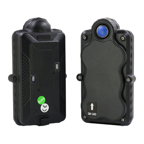
2. Product Image
3. Installation Manual
3.1 SIM Card Pre-installation, specification note
a. GSM Sim Only
b. SIM card should have its GPRS function enabled.
c. SMS request will function only if Caller ID function is enabled.
d. If SIM card is locked via PIN, please unlock SIM.
3.2 SIM Card Installations and Removal
b. Take out the sticker
c. Insert SIM card into the SIM slot, metal face up, clipped corner to the right.
d. Call the device SIM number and it is supposed to get through without answer, it means
installation is done.
3.3 Device Installations
a. Avoid all metal environment to make sure device is able to receive GSM and GPS signal.
b. Avoid high temperature environment like above the car engine
4. Button Operation
For the first time activating the device, once Sim is inserted,
device will be on automatically. No any button operation is
needed.

4.1 Button Operation for GPS function
NOTE: “button”presses must be less than 2 seconds each in all uses
a. GPS On: Press control button 5 times. Call the device SIM number and it is supposed
to get through without answer, it means the device is on.
b. GPS Off: Press control button 10 times. Call the device SIM number and it can not get
through, it means the device is off.
c. LED Torch on: Short press the button 1 time then long press the button for 3 seconds
to turn on the LED torch function.
d. Power bank on: long press the power button more than 3 seconds to turn on the
power bank function, the power LED indicator will show the remaining power.
5. Operation Commands Guide
5.1 Set APN: (VERY IMPORTANT AND MUST BE DONE 1ST) For the device to
send data to the server, this command MUST be enabled.
SMS: *apn*AXXX*BXXX*CXXX* This command sets the telecom Access Point Name.
BXXX refers to user name, CXXX refers to password.
If there is no user name and password required, send as *apn*AXXX*
If there is user name but no password required, send as
*apn*AXXX* BXXX*
APN information can be checked on local telecom website.
You will receive the following text: "Notice: APN is set to XXX. User name: XX. Password:
XX”
5.2 Registering the “Master”Controller
SMS to the device: *master*123456*+1XXXXXXXXXXXX*, (For instance, master
controller phone number is +1XXXXXXXXXXXX. +1 refers to the country code.
XXXXXXXXXXXX is the cellphone number. Please make sure country code is included, and
digit 0 is not needed before cell phone number)
Device Response: "Notice: Cell Phone # xxxxxxxxxx is set to master controller, the
password is 123456.”(The device has a default password of “123456”to initially program
in your PDA/Phone.
NOTE: The device will ONLY listen and respond to instructions from this number unless
you choose to turn on the multi controller function and open the device to any cell phone
number.

5.3 Changing the Password:
SMS: *password*654321* (654321 refers to new password)
You will receive the following text: "Notice: The password change is successful for
+1XXXXXXXXXX. The new password is 654321.”
Note: Changing password command has to be sent from master controller number.
6. Motion Detected Alert
The Master Controller will receive an alert (call or SMS) once the device detects vibration
indicating possible motion.
6.1 Vibration sensitivity:
The device you have purchased is equipped with a sensitive Vibration detection
system. The motion sensor sensitivity rate can be set by SMS command.
SMS: *sensitive*1-5* (where X = 1-5, 1 being the most sensitive, 5 the least, default
setting is 1)
1=3 seconds continued vibrating
2= 6 seconds continued vibrating
3= 9 seconds continued vibrating
4=12 seconds continued vibrating
5=15 seconds continued vibrating
Device Response: “Notice: Vibration sensitivity is set to 1-5.”
6.2 SMS or CALL Alert Settings:
With the vibration detection system. There will be a Call alert (call master number 2
times) or a SMS alert generated and send to master number, when any motion is detected
after 3 minutes of non-movement. The system default setting is call alert, and can
be turned off by SMS command
SMS: *alertoff*
Device Response: “Notice: System has ended alert function.”
SMS: *smsalert*
Device Response: “Notice: System has entered SMS alert function.”
SMS: *callalert*
Device Response: “Notice: System has entered call alert function.”
6.3 Period Motion Alert
System will enable motion alert function at appointed periods, up to 3 time periods. Time
format need to be in military time and can be set to hour. e.g. 0811,1418 refers to
8:00-11:00,14:00-18:00 of the day.
SMS:*continuousalert*0-23*0-23*
Device Response: “Notice: System has enabled period alert function at appointed time
period.”

SMS:*continuousalertoff*
Device Response: “Notice: System has ended period alert function.”
7. SMS Location Query
The GPS module establishes location and creates an event, which is sent immediately.
The data packet returned via SMS includes battery level and any applicable alert mode.
User can track the device location via SMS whenever, wherever.
7.1 SMS: *locate*
This command “Pings”the unit from the master controller for a spot location report
delivered via SMS back to the Master Controller.
Device Response: You will receive back a text include latest information of latitude,
longitude, date, time and ranking. And you can find this location in details from the
tracking website.
7.2 SMS: *locateaddress*
Device Response: You will receive back a text include rough address information of the
device. Tracking website is not required.
7.3 SMS: *locatemap*
You will receive back a text message with a google map link, click the link in order to view
the location through cellphone browser. It is suitable for smart phone user only.
8. Remote Listening
The device is equipped with an audio DSP which enable master controller to monitor the
environmental sound via calls. Master controller can enable the bugging function either by
calling the device or command the device to call back
8.1 SMS: *callin*
Enables the Master controller to call the device to start listening within 30mins after the
SMS is sent.
8.2 SMS: *callback*
The device will call the master controller enabling the Maser Controller to listen when
the call is accepted.
9. Website Tracking
Tracking Website: www.miitown.com
Account Login ID: Registered Master phone number. It's the same number as 5.2.
Account Login Password: Default as 123456.
It can be changed on the tracking website.
Recommended Web browser are Chrome, Firefox or cellphone default browser.

9.1 Real-time Tracking
This function delivers a highly granular tracking record of a specific route. Once motion is
detected, every 10 seconds locate records are uploaded every 1 minute to the server
during motion.
This function is suitable for speed moving object tracking. And it works in motion only.
9.1 By SMS
SMS: *routetrack*1-99* (1-98 represents hours of accumulated data, 99 means
always on)
Device Response: “Notice: System has entered routetrack function for *XX* hours.”If
you sent 99 the device responds: “Notice: Routetrack function is set to always on.”
9.1.1 Real-time tracking location data collecting interval.
The smaller interval, the higher accuracy, but the higher power consumption.
SMS *rsampling*1-999* (1-999 represents seconds of data collecting interval, default
as 10 seconds)
9.1.2 Real-time tracking location data upload interval. The smaller interval, the
higher accuracy, but the higher power consumption.
SMS *rupload*60-999* (60-999 represents seconds of data uploading interval,
default as 60 seconds, minimum rate should not be less than 60)
SMS *routetrackoff*
Device Response: “Notice: System has ended routetrack function.”
9.2 Check Location
This check function enables device to collect location data regularly and uploaded to
server in appointed interval. This command can be used both in idle and in motion, and
able to work with route track function at the same time.
Check by hour
SMS: *check*0-99*(0-99 represents hours of data upload interval, default as
*check*0*)
Check by minute
SMS: *checkm*10-999*(5-999 represents minutes of data upload interval, )
SMS:*checkoff*
Device Response: “Notice: System has ended check function.”

Noted:
1. Check function is able to work with routetrack command at the same time.
2. System is default as *check*72*. One location will be uploaded to server every 72
hours.
3. Location will be uploaded to server no matter device is in motion or not
9.3 Appointed Time Tracking
Appointed Time Map Location. Check map location at appointed time, up to 3 time points.
Time format need to be in military time and can be set to every half hour. e.g. 0830,
1400,1830 refers to 8:30, 14:00,18:30 of the day.
SMS:*timinglocatemap*XXXX*XXXX*XXXX*
Device Response: You will receive back a text message with a google map link, click the
link in order to view the location through cellphone browser. It is suitable for smart phone
user only.
SMS:*timinglocateoff*
Device Response: “Notice: System has ended timing locate function.”
9.4 Period Tracking
Period Tracking. GPS Location data will be uploaded to server during the appointed
periods, up to 3 time periods. Time format need to be in military time and can be set to
every half hour. e.g. 08001100,14001830 refers to 8:30-11:00,14:00-18:30 of the day.
SMS:*periodlocate*XXXXXXXX*XXXXXXXX*
Device Response: “Notice: System has enabled period locate function at appointed time
period.”
SMS:*periodlocateoff*
Device Response: “Notice: System has ended period locate function.”
9.5 Track Off
Track off will end all the tracking functions except check function.
SMS:*trackoff*
Device Response: “Notice: System has ended all tracking functions.”
9.6 Upload Alert
The upload alert function enables device upload alert status to the server including
motion alert, low battery alert and wire cut alert, drop alert etc. User can track

alert status on the tracking website.
This function is default as ON.
SMS:*uploadalert*on*
Device Response: “Notice: System has enabled upload alert function.”
SMS:*uploadalert*off*
Device Response: “Notice: System has disabled upload alert function.”
9.7 Online Control
The online command function enables device to connect with server for 15 minutes, and
user will be able to send online command from the tracking website.
SMS:*onlineon*
Device Response: “Notice: System has enabled online control function. Data will be
uploaded every 30 seconds for 15 minutes.”
SMS:*onlineoff*
Device Response: “Notice: System has disabled online control function.”
10. Deep Sleep
The Deep Sleep function enables the device to be available for long working periods as
needed, tracking remotely when either the timer wakes the unit or motion is detected.
10.1 Sleep
Device will enter deep sleep in appointed time interval and will be awake for 12
minute to upload 1 GPS location. If no new command,call or new motion is
received during the 12 minutes, device will enter sleep function again.
SMS: *sleep*1-99* (1-99 represents hours of deep sleep period. )
Device Response: “Notice: System is going to enter deep sleep function, data will be
uploaded every XXX hours.”
10.2 Motion Sleep
Device will enter deep sleep and will be awaked by motion, meanwhile upload the current
location, and will wait for 12 minutes for further command. If no new command,call or
new motion is received during the 12 minutes, device will enter sleep function again. And
the circle repeats.
10.2.1 SMS: *sleepv*
Device Response: “Notice: System has enabled deep sleep with motion call alert
function.”
10.3 Period Motion Sleep

Device will enter deep sleep for appointed time period and will be awaked by
motion, meanwhile upload the current location, and will wait for 12 minutes for
further command. If no new command,call or new motion is received during the
12 minutes, device will enter sleep function again, until appointed period ends.
Please input time period.
SMS: *sleepv*1-99* (1-99 represents hours of deep sleep period, system will be activated
with motion during this period. )
Device Response: “Notice: System has enabled deep sleep with motion call alert function
for XXX hours.”
10.4 Sleep Off
SMS: * sleepoff*
Device Response: “Notice: System has ended all sleep functions.”
11. Status query
SMS: *status*
System Health and status check. Returns text message indicating various system
diagnostics
12. Multi Controller
This allows any SMS enabled cell device to query the unit for location, status, etc.
121. 1 SMS: *multiquery*
“Notice: Multi query feature enabled.”
121. 2 SMS: *multiqueryoff*
The unit will now only respond to the Master controller.
Device Response: to the Master Controller: “Notice: Multi query feature disabled.”
13. Device Information
SMS: *about*
You will receive a text message include software edition information and device’s serial
number.
14. Timezone
The timezone need to be set before using the period motion alert, appointed
time tracking or period tracking function.
System is UTC time format and time zone need to be set by SMS.
SMS: *timezone*0-24*(0-24 represents different timezone, default as 8) eg Italy=
*timezone*2* UK= *timezone*0* Australia Perth = *timezone*8*

15. SOS Alert
The Master controller number is the default number to receive the SOS
message, other mobile phone numbers can be bounded together to receive the
SOS message by below operation 15.1
15.1 Registering the panic button bounded number
SMS to the device:
*master*123456*+1XXXXXXXXXXXX*+AXXXXXXXXXXXX*+BXXXXXXXXXXXX
*+CXXXXXXXXXXXX*,
+1XXXXXXXXXXXX refers to master controller number. +1 refers to the country code.
+AXXXXXXXXXXXX, +BXXXXXXXXXXXX, +CXXXXXXXXXXXX refer to panic button bounded
number. Up to 3 phone numbers can be bounded
NOTE: Please make sure country code is included, and digit 0 is not needed before cell
phone number
Device Response: "Notice: Cell Phone # xxxxxxxxxx is set to master controller, the
password is 123456.”(The device has a default password of “123456”to initially program
in your PDA/Phone.
NOTE: All bounded number will receive the above response when command is received.
15.2 Panic Button
1. Short press button 2 times and then long press button 1 time more than 3 seconds,
system will send 2 SOS SMS to bounded phone numbers.
Bounded phone numbers will receive SMS “SOS! HELP! SOS!! HELP!! SOS!!! HELP!!!”
SMS: *soson*
Device Response: “Notice:SOS alert function enabled.”
SMS: *sosoff*
Device Response: “Notice:SOS alert function disabled.”
NOTE: The default setting is OFF. Please send SMS *soson* to enable this function. And all
bounded numbers are capable to control device as master controller does.
16. Low battery Alert:
The device is equipped with an automatic “Low Battery”detection and alert when the
battery drops to 20% of it’s capacity. An alert SMS will be sent to appointed phone
number and the real-time tracking function will be turned off for power saving.
Appointed alert number settings
Default alert phone number is registered master number, and it can be changed as
needed.

SMS: *lowbat* +1XXXXXXXXXXXX*, (For instance, master controller phone number
is +1XXXXXXXXXXXX. +1 refers to the country code. XXXXXXXXXXXX is the cellphone
number. Please make sure country code is included, and digit 0 is not needed before cell
phone number)
17. Power bank
17.1 Feature:
a. Build in 3000mAh(T903)/5000mAh(T905) Lithium polymer battery.
b. Micro USB input, USB-A output, can charge mobile phone, tablet PC, PDA, MP3, MP4
and so on.
c. With low voltage and over voltage protection.
d. The DC to DC output efficiency up to 80-95%
e. The power LED indictor shows the remaining power as below table.
Power
indicator
1 LED on
2 LED on
3 LED on
4 LED on
Power
<25%
<50%
<75%
100%
17.2 Operation guide:
a. Input: Charge T903 inside battery by Micro USB (DC 5V), the charging LED glitter
during charging.
b. Output: Connect T903 with other devices like mobile phone by the USB cable, long
press the power button more than 3 seconds to turn on the power bank function, the
power LED indicator will show the remaining power.
c. The USB input and USB output can be work at the same time.
d. In order to save power, the power LED indicator will be off after 10 seconds. Short
press the button 1 time, the LED will be on again.
f. If no any operation (no input , no output) for 20 seconds, the power bank function will
be off automatically for saving power.
g. For the first time use, if the power LED glitter, means power is very low, please
recharge it before using.
h: LED Torch function: Short press the button 1 time then long press the button for 3
seconds to turn on the LED torch function.
17.3 Attentions:
a. When this product is standby, the power of the built-in battery will automatically
release, the normal storage time is around 3 months when this product is fully charged.

b. This product has over charging and over discharging protection, the USB output will be
cut off automatically if the battery voltage is too low.
c. It is normal that there is heat release when this product is charging in or out, which will
turn back to the normal temperature after the charging completed.
17.4 Cautions:
a. Do not use the battery in bathrooms etc. with high humidity or where it may be
exposed to water.
b. Do not use or store at places with high temperatures, high humidity or much dust.
c. Do not modify or disassemble the battery.
d. Young children should be supervised to ensure that they do not play with the appliance.
e. Do not throw the battery into a fire.
f. Do not subject the battery to strong impacts and do not throw it.
17.5: Specification
a. Input: DC5.0V 1000mA(Micro USB);
b. Output: DC5.0V 1000mA (USB-A);
c. Charging time: 6hours(T903) 10hours(T905)
d. Standby power: ≤250uA
e. Battery: 3000mAh(T903)/5000mAh(T905) Lithium polymer battery
Command Setting List
Function
Command
Description
APN Setting
*apn*AXXX*BXXX*CXXX*
This command sets the
telecom Access Point
Name. BXXX refers to
user name, CXXX refers
to password.
Master Setting
*master*123456*+1XXXXX
XXXXXXX*
+1 refers to the country
code. XXXXXXXXXXXX is
the cellphone number.
Please make sure country
code is included, and 0 is
not needed before cell
phone number

Function
Command
Description
Password Changing
*password*654321*
Original password is
default as 123456.
654321 refers to new
password.
Vibration Sensitivity
Setting
*sensitive*1-5*
1 being the most
sensitive, 5 the least.
Default setting is 1.
Motion Alert
*callalert*
Call alert will call master
number 2 times when
motion is detected after 3
minutes non-movement.
*smsalert*
SMS notification will sent
to master number when
motion is detected after 2
minutes non-movement.
*alertoff*
End Call/SMS alert
Period
Motion
Alert On
*continuous
alert*0-23*0-
23*
Device will enable motion
alert function at
appointed period of time
*continuousalertoff*
End Period Motion Alert
LLC Query
*locate*
Latest information of
latitude, longitude, date,
time and ranking.
Address Query
*locateaddress*
Address information of
current location.
Google Map Search
*locatemap*
Google Map link with
current location.
Audio Monitoring
Call in
*callin*
Call the device to start
listening within 30mins
after the SMS is sent.
Audio Monitoring
Call back
*callback*
The device will call the
master phone number
and enabling the Maser
Controller to listen when
the call is accepted.

Function
Command
Description
Real-time Tracking
*routetrack*1-99*
1-98 represents hours of
accumulated data, 99
means always on.
Sampling Interval
*rsampling*1-999*
1-999 represents
seconds of data
collecting interval, default
as 10 seconds.
Upload Interval
*rupload*60-999*
60-999 represents
seconds of data
uploading interval,
default as 60 seconds,
minimum rate should not
be less than 60.
Real-time Tracking
Off
*routetrackoff*
End routetrack function.
Check Location
*check*0-99*
Track by hour. 0-99
represents hours of data
upload interval, default
as *check*0*
*checkm*10-99*
Track by minute. 5-99
represents minutes of
data upload interval
*checkoff* / *check*0*
End check function
Period Tracking
*periodlocate*XXXXXXXX*
XXXXXXXX*
GPS location data will be
uploaded to server at
appointed periods, up to
3 time periods.
*periodlocateoff*
End period tracking
function.
Appointed Time
Tracking
*timinglocatemap*XXXX*X
XXX*XXXX*
Check map location at
appointed time
*timinglocateoff*
End appointed time
tracking function
Track Off
*trackoff*
End all the tracking
functions expect check
function.

Function
Command
Description
Upload Alert
*uploadalert*on*
All alerts will be uploaded
to server
*uploadalert*off*
End upload alert function
Online Control
*onlineon*
Enable online control
function
*onlineoff*
End online control
function
Deep Sleep Setting
*sleep*1-99*
1-99 represents hours of
deep sleep period.
Period Motion Sleep
* sleepv*1-99*
Period Motion Sleep. 1-
99 represents hours of
deep sleep period.
Motion Sleep
* sleepv*
Motion Sleep function
with motion alert.
Sleep Off
*sleepoff*
End Deep Sleep function.
Status query
*status*
Check system status
Multi Controller
*multiquery*
Enable multi controller
function
*multiqueryoff*
End multi controller
function
SOS Alert
*soson*
Enable SOS alert
function
*sosoff*
Disable SOS alert
function
Device Information
*about*
Software edition
information and device’s
serial number.
This manual suits for next models
1
Table of contents
Other Vjoycar GPS manuals


