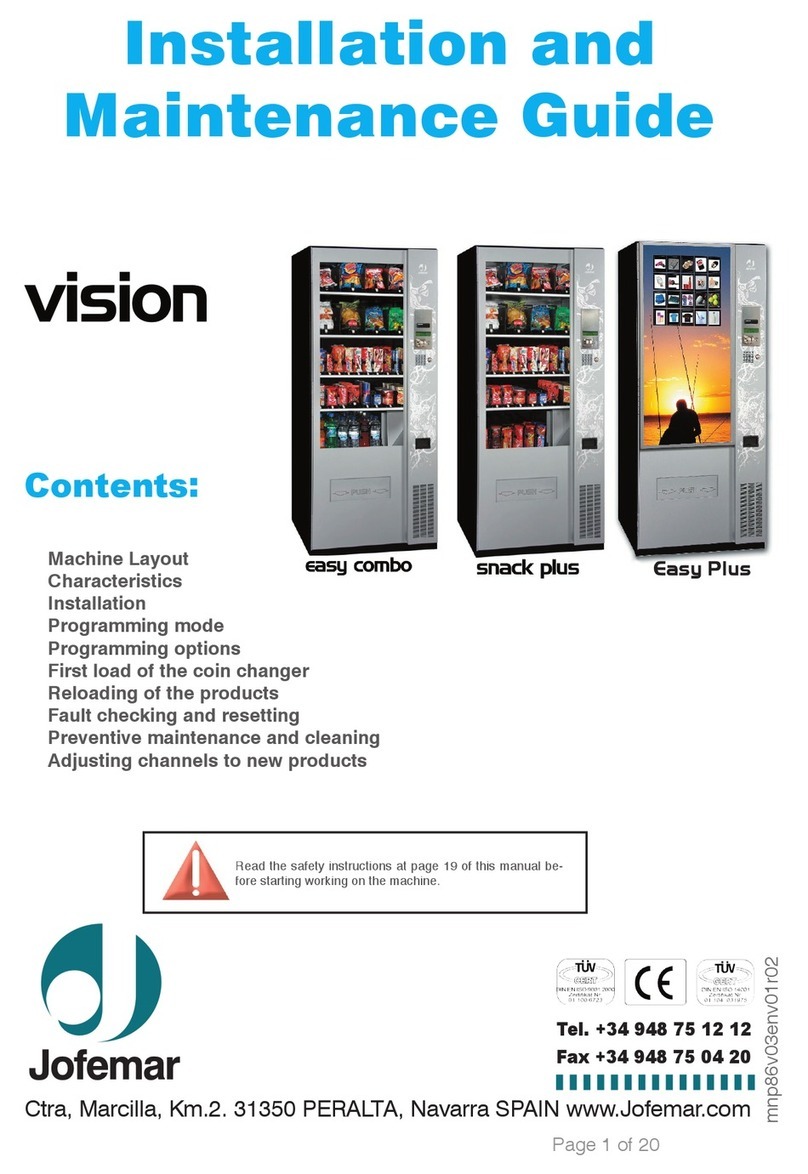
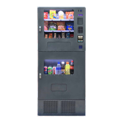
Jofemar Vision Snack Plus User manual

vision
Snack Plus/Easy Combo
//
Vending
MNP86V03GBV00 Date: 2010/06/14 Rev. 0 PAGE 1 OF 62
English
vision
Snack Plus
Easy Combo
TECHNICAL MANUAL

vision
Snack Plus/Easy Combo
//
Vending
MNP86V03GBV00 Date: 2010/06/14 Rev. 0 PAGE 2 OF 62
WARNING!
Read the following instr ctions caref lly before sing yo r machine:
◊ Remove plastic pl gs from bottom of machine and p ace it on the f oor before
opening and unpacking.
◊ When discarding packaging material or an old machine, p ease consu t about
recyc ing.
◊ Since the machine has a cooling nit, it shou d be transported in vertica position
and it shou d not be connected to mains unti 2 hours have e apsed after conc uding
the unpacking and insta ation process.
◊ Before connecting to mains, make sure that the power supp y characteristics
coincide with those of the machine.
◊ The power cable pl g shou d be insta ed so the machine can be easi y
disconnected from mains.
◊ If the power cable is damaged, it shou d be rep aced by the manufacturer or after
sa es service or simi ar qua ified personne to prevent hazards.
◊ Place a r bber protection around the power cab e in the s ot of the id of the cab e
winding recess.
◊ Do not b rn or throw away the battery. Batteries shou d be disposed of in
accordance with oca aws and regu ations and may be recyc ab e.
◊ Protect the machine against humidity, dust, dirt, etc. You shou d particu ar y avoid
any obstruction of the venti ation grids.
◊ Do not clean the machine with concentrated products as they may attack the
painted and wood surfaces and a ter the co our.
◊ Freq ent cleaning, can prevent breakdowns and extend the machine's service ife.
◊ The machine sho ld be installed in a vertica position, with a maximum back to
front or atera ti t of 5% (~2°).
◊ If yo need to replace the power s pply cable, p ease rep ace it with the
appropriate one for your country:
Argentina, Jofemar code 5500014.
Austra ia, Jofemar code 5500006.
Spain (STANDARD), Jofemar code 5500000.
UK, Jofemar code 5500011.
Switzer and, Jofemar code 5500004.
USA, Jofemar code 5500010.
Jofemar S.A.
Ctra. de Marci a km. 2, 31350 PERALTA. Navarra, SPAIN.
http: // www.jofemar.com Te . +34 948 75 12 12 Fax +34 948 75 04 20

vision
Snack Plus/Easy Combo
//
Vending
MNP86V03GBV00 Date: 2010/06/14 Rev. 0 PAGE 3 OF 62
TABLE OF CONTENTS
1. Symbo s...................................................................................................................... 4
2. Operating conditions................................................................................................... 4
3. Description of components.......................................................................................... 4
3.1. Main technica features....................................................................................... 5
3.1.1. Door ......................................................................................................... 6
3.1.2. Cabinet..................................................................................................... 9
3.2. Vo ume and weight ........................................................................................... 14
4. E ectric-e ectronic specifications ........................................................................... 15
4.1. Initia e ectrica insta ation ............................................................................ 15
4.2. Product dispenser channe ............................................................................... 15
4.3. Disp ay card...................................................................................................... 16
4.4. Contro card...................................................................................................... 16
4.5. Re ay card ........................................................................................................ 17
4.6. Photodiode and phototransistor cards............................................................... 17
4.7. E ectronic thermometer card............................................................................. 18
4.8. Modem communications interface card............................................................. 19
4.9. R 134A CFC-free coo ing unit ........................................................................... 19
4.10. E ectronic contro system ................................................................................ 19
4.11. T-15 va idator (se ector) .................................................................................. 20
4.12. Compact J-2000 ............................................................................................. 20
4.12.1. Coin separator...................................................................................... 21
4.12.2. Return carriage..................................................................................... 21
4.13. Recovery motor .............................................................................................. 21
4.14. BT-10 banknote reader................................................................................... 22
4.15. E ectrica diagram ........................................................................................... 23
5. Insta ation and start up............................................................................................. 24
5.1. Insta ation ........................................................................................................ 24
5.2. Start up............................................................................................................. 24
5.3. Memory reset.................................................................................................... 24
5.4. Restocking machine trays................................................................................. 25
5.5. Product se ection .............................................................................................. 25
5.6. Updating the machine program......................................................................... 26
5.7. Machine programming mode ............................................................................ 27
5.7.1. Standby menu without credit (standby status)......................................... 27
5.7.2. Standby menu with credit (working status).............................................. 28
5.7.3. Programming menu (programming status).............................................. 28
5.8. Programming addresses................................................................................... 30
6. Troub eshooting ........................................................................................................ 52
7. Annexes.................................................................................................................... 55
7.1. Periphera s ....................................................................................................... 55
7.2. Jams and changes in the J-2000 compact tubes............................................... 57
7.3. Insta ing and removing channe s ...................................................................... 57
7.4. Transport feet and adjustab e eve ing feet....................................................... 58
7.5. C eaning and Maintenance ............................................................................... 59
7.6. Recyc ing.......................................................................................................... 60
7.7. Environment ..................................................................................................... 60
8. Regu ation ................................................................................................................ 61

vision
Snack Plus/Easy Combo
//
Vending
MNP86V03GBV00 Date: 2010/06/14 Rev. 0 PAGE 4 OF 62
1. Symbols
This symbo means there are more detai ed exp anations on this subject
e sewhere in the manua .
This symbo means that the text in question refers to programming.
This symbo indicates very important information.
This symbo is a warning of high vo tage hazard.
This symbo indicates that a given materia shou d not be disposed of as
domestic waste.
This symbo indicates that a given materia is recyclable.
This symbo indicates that Jofemar is committed to the environment.
2. Operating conditions
This machine has been specifica y designed to work in interiors. The machine eaves the
factory adjusted to work proper y at an ambient temperature between 5° C and 32° C
with a maximum humidity of 60% and a maximum oad of 100 kg of products.
3. Description of components

vision
Snack Plus/Easy Combo
//
Vending
MNP86V03GBV00 Date: 2010/06/14 Rev. 0 PAGE 5 OF 62
Position Description Position Description
A Door M F uorescent amps
B Disp ay N Cabinet
C Coin return pushbutton Ñ Trays and channe s
D Coin in et O Door microswitch
E Lock P Vau t
F Se ection pushbutton pane Q E ectronics support
G Coin out et R RS-232 connection
H Product de ivery opening S Fuse/Fuse ho der
I Compact T Main switch
J Se ector U Coo ing unit
K Programming pushbutton V Product de ivery bin
L Safety g ass
3.1. Main technical feat res
► Dispenses a wide range of products of different sizes and shapes —different types of
drinks and snacks, sandwiches, different objects, etc.
► F exib e configuration and programming, up to 8 height-adjustab e trays with up to 10
channe s each for inc uding various product formats.
► FIFO product de ivery system a ternating dispensing from different channe s if they are
inked through programming.
► LCD screen with direct status and programming messages.
► Te emetry-ready, inc uding remote reading of audits, sa es, incidents and changes in
programming options.
► Sa es accounting and contro , as we as data output via RS-232-C. The machine can
a so be programmed via a Jofemar e ectronic termina .
► Product pushing force can be programmed independent y for each se ection.
► Continuous operationa se f-testing.
► Automatic safety system that prevents the machine from se ing products not fit for
consumption thanks to the option of programming an expiry date for each se ection
number or channe .
► Easi y dividab e into temperature zones, coo ed and ambient and adjustab e.
► Programmab e machine ight on and off.
► Meta parts are bui t with 1.5 mm (1/17”) gauge ga vanised p ate treated against
corrosion and an externa rustproof paint ayer.

vision
Snack Plus/Easy Combo
//
Vending
MNP86V03GBV00 Date: 2010/06/14 Rev. 0 PAGE 6 OF 62
3.1.1. Door
On the front part of the door we can see: the safety g ass, the BT-10 banknote reader
(optiona ), the J-130 card reader (optiona ), the disp ay, the coin in et, the coin return
pushbutton, the product se ection pushbutton pane , the ock, the coin return box and the
product de ivery opening. On the back of the door we find: the programming pushbutton,
the J-2000 compact and the T-15 se ector.
Safety glass
Made of doub e g azed, ow emission climalit safety g ass with a
12 mm (1/2“) gap offering top strain re iabi ity.
It provides a view of the products and their ocation on the trays.
Height (H) Width (W) Thickness (F)
Snack Pl s 1169,5 mm
46”
561 mm
22”
22 mm
6/7”
Easy Combo 1169,5 mm
46”
561 mm
22”
22 mm
6/7”
Fig. 01
BT-10 banknote reader
● The BT-10 banknote reader consists of a reading head that reads
the banknote and va idates it against a set of patterns it has stored
in memory. Shou d the banknote be recognised, it is sent to a
stacker used for storing the banknotes (capacity 210).
● The front cover of the banknote reader has severa status LEDs,
green and red, which show the reader’s activity at a times as we
as possib e fau ts.
● This component comes as an option.
● Banknote readers using the MDB communications protoco can
on y be used if the program version is for working with the compact
MDB. Fig. 02

vision
Snack Plus/Easy Combo
//
Vending
MNP86V03GBV00 Date: 2010/06/14 Rev. 0 PAGE 7 OF 62
J-130 card reader
• JOFEMAR J1oxx card reader. It can be used for purchases with cards (norma or
free), to recharge cards with credit, to program the machine and to obtain audits.
Communications with the card reader take p ace via RS-232. When working with a J-
2000 MDB coin changer, the card reader is connected to one of the two RS-232
outputs on the machine contro card. When working with a J-2000 EXECUTIVE coin
changer the card reader shou d be connected to coin changer (see the manua for
the J-2000 EXECUTIVE).
Fig. 03
• The MDB card reader with which we can on y
make sa es with cards, can be used if the
program version is for working with the compact
MDB.
• This component comes as an option.
Display
It is essentia y used in machine programming
operations to disp ay accounting data and technica
incidents and shows the credits entered or the sa e
prices of the products.
Fig. 04
Coin inlet
There are two types of coin in et: the standard coin s ot (fig. 05) and the vanda -proof,
security mode (fig. 06) which is optiona .
Fig. 05
Fig. 06
Coin ret rn p shb tton
It is ocated to the right of the coin in et, its function is to return coins, (if you wish to
recover the amount that you have inserted in the machine).

vision
Snack Plus/Easy Combo
//
Vending
MNP86V03GBV00 Date: 2010/06/14 Rev. 0 PAGE 8 OF 62
Prod ct selection p shb tton panel
The pushbutton pane consists of 16
keys divided into numerica and
a phabetica (fig. 07). In addition to being
use to se ect a product, they are a so
used in machine programming and the
configuration.
Fig. 07
Lock
These machines feature a secure ocking system consisting of a p ate with three vanda -
proof anchoring points.
Programming p shb tton
It is ocated inside the door. This pushbutton is used to access a programming
functions: sa e prices, messages shown by the disp ay, resets, etc.
J-2000 compact (MDB/EXECUTIVE)
The machine can work with two different coin changers. The machine program changes
depending on the coin changer being used.
• J-2000 MDB coin changer without recovery motor (see the manua for the J-2000
MDB). The communication between machine and compact takes p ace using the
MDB protoco . The machine works as master whi e the compact works as s ave.
When the machine is in service, the disp ay shows the time and the temperature if the
type of sa es programming is simp e or mixed sing e 2 (
address 15). In sing e sa es
mode on y the coins or banknotes whose va ue can be returned wi be accepted and the
maximum credit that we can enter can never exceed the maximum recovery (
address
16). Furthermore the maximum recovery is updated automatica y with the higher price in
the case where such price exceeds the va ue of the maximum recovery.
In mixed sing e sa es mode 2, when accepting coins or banknotes no whether they can
be returned or not is not taken into account.
In the two types of sa es the credit that can be accepted is imited by the higher price
programmed. Therefore to ensure the proper operation of the machine check that the
maximum recovery and the prices are proper y programmed (
address 16 and
address 00 respective y). In sing e sa e mode you need to insert money unti you reach
or exceed the price of the desired product. When you use they key pad to enter the
product se ection, the disp ay shows the price of the product. If such price is ess than or
equa to the money inserted, the product is not out of stock and there is enough change,
se concede the sa e.

vision
Snack Plus/Easy Combo
//
Vending
MNP86V03GBV00 Date: 2010/06/14 Rev. 0 PAGE 9 OF 62
• J-2000 EXECUTIVE coin changer without recovery motor (see the manua for the
J-2000 EXECUTIVE). The communication between machine and compact takes
p ace using protoco A. The machine is s ave of the compact, which acts as master.
If the machine has not detected an executive coin changer connected to it (because it
has not received any command), the disp ay wi show an error message. The same error
wi be shown on the disp ay after the communication between coin changer and
machine has been interrupted for 30 seconds. When you are inside the programming
addresses, the machine vo untari y interrupts communication with the compact.
Communication is re-estab ished when you access standby without credit.
You can work both in coin changer price storage
mode and in machine price storage mode. In
both cases you shou d program the option in the
coin changer that makes it refresh the machine
disp ay, to be ab e to consu t the price of each
product without inserting credit.
Dimensions Weight Fig. 08 Fig. 09
353 x 137 x 82 mm
13 8/9” x 5 2/5” x 3 2/9“
2,8 kg
6 b. MDB
353 x 137 x 82 mm
13 8/9” x 5 2/5” x 3 2/9“
2,8 kg
6 b.
EXECUTIVE
T-15 coin selector
Fig. 10
The T-15 coin se ector is a premium va idation device that can
recognise up to 24 different coins or tokens. It has a coin
separator coi that a ows it to accept or reject coins.
COIN AND TOKEN CHARACTERISTICS
Thickness range Diameter range
1 mm to 3,2 mm
2/51“ to 1/8“
16 mm to 32 mm
5/8“ to 1 1/4“
3.1.2. Cabinet
The cabinet ho ds the product trays, the vau t, the e ectronic contro system, the coo ing
unit (for vision Easy Combo) and the product de ivery bin.
The structure of the cabinet is injected with po ythene foam for improved insu ation and
better consistency.

vision
Snack Plus/Easy Combo
//
Vending
MNP86V03GBV00 Date: 2010/06/14 Rev. 0 PAGE 10 OF 62
Trays and channels
Fig. 11
There are two types
of trays and they are
the part of the
machine where the
product is stored, as
there are various
configurations, one
machine can have up
to 8 trays maximum
depending on the
products that you
wish to dispense.
Dimensions
TRAYS Height (H) Width (W) Depth (D) Weight
Large 115 mm
4 1/2“
642.2 mm
25 2/7“
675 mm
26 4/7“
5,250 kg
11 b.
Small 115 mm
4 1/2“
428 mm
16 6/7“
675 mm
26 4/7“
3,900 kg
8 b.
Capacity up to 10 channe s per tray depending on configuration.
Sma tray with 1 to 7 channe s Large tray with 1 to 10 channe s
Fig. 12 Fig. 13
The
vision
machines se the products shown in the fo owing tab e:
vision
SNACKS DRINKS SANDWICHES
PRODUCTS
Sachets Cans Non-edib e
Snack
Pl s Sweets Bott es
Pastries Tetra bricks Of any type
Easy
Combo Choco ates Dairy
products
NOTE: For other types of products or specia sizes p ease
contact your Jofemar distributor.

vision
Snack Plus/Easy Combo
//
Vending
MNP86V03GBV00 Date: 2010/06/14 Rev. 0 PAGE 11 OF 62
Va lt
The vau t has a ock and arge capacity, with a se f- ocking option
enab ed when it is removed. There are severa options: p astic,
with door and ock, and se f- ocking.
Plastic With door Self-locking
Capacity 2 itres 2 itres 2 itres
Fig. 14
Electronic control system
It consist of severa printed circuit cards:
• Control car , which governs a of the machine’s movements, as we as
programming of options and product audits, and a so power sources that supp y
appropriate vo tages for ogic contro , to move the tray motors, to supp y periphera s
on bus 485 and to supp y the product detection system. The program is recorded in
FLASH memory.
• Relay car , which has the re ays that contro the connection to the compressor,
e ectrova ve and showcase ight. The connection for these systems that work at 220
VAC is synchronised by setting the vo tage to zero.
• Custom isplay car , which has the LCD disp ay, the buzzer contro and
connections for the product se ection pushbutton pane and programming button. It is
a periphera contro ed by the contro card with which it communicates using bus 485.
It is possib e to adjust the contrast of the messages on the disp ay by turning a
potentiometer.
• Photo io e an phototransistor car s of the product detection system.
• Electronic thermometer car .
• Mo em communication interface car .
R 134A CFC-free cooling nit (Easy Combo)
It is managed by a program which contro s the temperature of the machine product ho d
e ectronica y.
The machine is equipped with a coo ing unit and a turbine to keep a constant working
temperature in the product ho d. This temperature, a so ca ed coo ing unit cut-off
temperature, is programmab e (
address 18). When the interna temperature rises
2.5 °C above the coo ing unit cut-off temperature, the coo ing unit turns on. When the
interna temperature again matches the cut-off temperature, the coo ing unit turns off.

vision
Snack Plus/Easy Combo
//
Vending
MNP86V03GBV00 Date: 2010/06/14 Rev. 0 PAGE 12 OF 62
The coo ing unit consists of a compressor and a condenser ocated in the ower part of
the cabinet, as we as an evaporator ocated inside the product ho d and an axia f ow
fan that coo s the condenser and the compressor motor. The coo ing gas used is the gas
indicated on the machine compressor. The turbine is a fan with two runners ocated
inside the product ho d which is permanent y in operation.
A. Compressor
B. Condenser
C. Fan
D. Evaporator
E. Turbine
Fig. 15
The machine carries out defrosting cyc es to prevent ice from bui ding up in the
evaporator of the coo ing unit, which wou d have adverse effects on the unit’s
performance. The defrosting cyc e consists of turning the coo ing unit off ong enough for
the ice bui d-up on the evaporator to disappear. A tota of 3 defrosting cyc es are carried
out a day at approximate y 8-hour interva s. The unit is further defrosted three hours after
the machine has been restocked with product; in this case the interna temperature wi
not be shown on the disp ay unti one hour after the defrosting cyc e began.
There is a s otted area to permit air circu ation through the inside area where the
compressor and condenser are ocated. This area is ocated at the front of the machine
cabinet.
The fo owing conditions shou d be met for proper coo ing system operation:
1º The s ots shou d be kept free of dust and you shou d check regu ar y that they are not
obstructed with bags, papers, etc.
2º At the back of the cabinet there is a window that provides access to the coo ing unit.
You shou d a ways keep the coo ing unit c ean to ensure a ong service ife.
The temperature is programmab e between 4 °C and 12 °C with zone division.
Note: For safety reasons, every time the unit is stopped and started, the
process is detained during a 4-minute interva .

vision
Snack Plus/Easy Combo
//
Vending
MNP86V03GBV00 Date: 2010/06/14 Rev. 0 PAGE 13 OF 62
Prod ct delivery bin
Dimensions
Height (H) Width (W) Depth (D)
465 mm
18 1/3“
505 mm
19 7/8“
240,5 mm
9 1/2“
Fig. 16
The product detection system ocated in
the product de ivery bin has a product
detector based on photodiodes and
phototransistors; so that when the
infrared beam is interrupted, the system
knows a product has fa en inside the
bin.
Lighting
The machine is perfect y i uminated
with two f uorescent amps fed by a
220 Vac supp y which are ocated
inside the cabinet, at the top (fig.
17), the tubes have a power rating of
13 W each and they are protected by
a diffuser fi ter which is s id a ong the
guides in that area.
Machines with a 110 Vac power
supp y wi have three 8 W
f uorescent amps.
Fig. 17
Anchoring
These machines are fitted with ho es and
supp ied with an anchoring kit (fig. 18)
that can be used to anchor the machine
to the f oor (fig. 19) or to the wa (fig. 20)
for greater stabi ity and support and to
prevent thefts.
Fig. 18

vision
Snack Plus/Easy Combo
//
Vending
MNP86V03GBV00 Date: 2010/06/14 Rev. 0 PAGE 14 OF 62
Fig. 19 Fig. 20
3.2. Vol me and weight
Dimensions Height (H) Width (W) Depth (D) Weight
Snack P us 1.825 mm
71 6/7“
800 mm
31 1/2“
970 mm
38 1/5“
268 kg
590 b.
Easy Combo 1.825 mm
71 6/7“
800 mm
31 1/2“
970 mm
38 1/5“
297 kg
655 b.
Vision Snack Pl s / Easy Combo

vision
Snack Plus/Easy Combo
//
Vending
MNP86V03GBV00 Date: 2010/06/14 Rev. 0 PAGE 15 OF 62
Fig. 21
4. Electric-electronic specifications
The coo ing unit, f uorescent amps, turbine and transformer are supp ied with mains
vo tage (220 VAC). They shou d therefore not be hand ed without disconnecting the
machine from mains.
Power s pply voltage
220 ± 10% VAC.
vision
Maxim m power Maxim m intensity
Snack Pl s 100 W 0,4 A
Easy Combo 830 W 3,5 A
4.1. Initial electrical installation
Prepare a 220-240 VAC, 50 Hz / 10A socket, protected with an automatic connection
system. The socket shou d match the machine p ug (European, with ground connection).
Fo ow a Low Vo tage Insta ation Regu ations and check that ground connection works
proper y once the machine has been insta ed.
4.2. Prod ct dispenser channel
There are three types of different product dispensers. Depending on the type of product
to be served, you can interchange these channe s, offering a wide range of
combinations. A maximum of 10 dispenser channe s can be added to each tray.
Fig. 22 Fig. 23 Fig. 24
Ref. code 8210061
(Fig. 22)
8210062
(Fig. 23)
8210063
(Fig. 24)
Motor power s pply 12 Vdc 12 Vdc 12 Vdc
Max. power
cons mption 3 W 3 W 3 W
To proper y dispense a product, the dispenser motor operation vo tage has to be
programmed ( address 25) to ensure the most appropriate dispensing speed for each
product.

vision
Snack Plus/Easy Combo
//
Vending
MNP86V03GBV00 Date: 2010/06/14 Rev. 0 PAGE 16 OF 62
4.3. Display card
The disp ay te s the contro card what keys have been pressed, showing messages on
screen and issuing the beeps sent by the contro card.
DISPLAY CARD CONNECTORS
A. Pushbutton pane
B. (Not in use)
C. (Not in use)
D. (Not in use)
E. Potentiometer for the
contrast of the disp ay
F. Programming pushbutton
G. Back ight
H. (Not in use)
I. Power supp y connection, Bus
485
J. Power supp y connection,
Bus 485
Fig. 25
4.4. Control card
Communication with the J-2000 compact and with the periphera s takes p ace under
different protoco s.
CONTROL CARD CONNECTORS
A. Transformer secondary and re ays K. (Not in use)
B. Connection bin product sensor L. Door microswitch connection
C. Connection tray motors M. RS-232 port connection (1)
D. Connection recovery motor N. RS-232 port connection (2)
E. Connection tray motors Ñ. 485 periphera s connection
F. (Not in use) O. MDB periphera s connection
G. (Not in use) P. LCD back ighting power supp y
H. Thermometer connection Q. Connection Executive
I. (Not in use) R. Connection periphera s MDB
J. Battery connection (temperature
contro er)
S. Connection periphera s 485

vision
Snack Plus/Easy Combo
//
Vending
MNP86V03GBV00 Date: 2010/06/14 Rev. 0 PAGE 17 OF 62
Fig. 26
4.5. Relay card
RELAY CARD CONNECTORS
A. Coo ing unit enab ing and ighting
B. Contro card power supp y
C. (Not in use)
D. Transformer connection
Fig. 27
4.6. Photodiode and phototransistor cards
Phototransistor Front photodiode Side photodiode
A. (Not in use) H. (Not in use) K. Power supp y and
atera sensing
B. Branch enab ing: power
supp y and status LED
I. Branch enab ing: power
supp y and status LED
C. (Not in use) J. Connection to side
photodiode
D. Machine power supp y
contro
E. (Not in use)
F. (Not in use)

vision
Snack Plus/Easy Combo
//
Vending
MNP86V03GBV00 Date: 2010/06/14 Rev. 0 PAGE 18 OF 62
G. Power supp y and atera
sensing
Fig. 28
The fo owing graph
(fig. 29) shows
communication and
distance between the
photodiodes,
phototransistors and
the side photodiode of
the product de ivery
bin (top view).
Fig. 29
4.7. Electronic thermometer card
The temperature of the product ho d is measured with an
e ectronic thermometer which can be p aced in different
ocations of the product ho d. Norma y, it is ocated ha f way up
the ho d.
Fig. 30

vision
Snack Plus/Easy Combo
//
Vending
MNP86V03GBV00 Date: 2010/06/14 Rev. 0 PAGE 19 OF 62
4.8. Modem comm nications interface card
A. MODEM connection
B. Input/output power supp y,
communication protoco 485
C. Input/output power supp y,
communication protoco 485
D. Battery charger
E. Power supp y MODEM
F. (Not in use)
Fig. 31
4.9. R 134A CFC-free cooling nit
EASY COMBO
Compressor make DANFOSS L´UNITE H.
Model SC 12 G CAE 4440 Y
Compressor power 3/8 HP
Coolant R-134 A
Displacement 12,9 cm
3
12,05 cm
3
Coolant charge 305 g 300 g
Power s pply of the fan of the condenser 230 Vac 110 Vac
Maxim m flow moving evaporator t rbine 325 m
3
/hour
4.10. Electronic control system
The e ectronic contro system is mounted on rai s inside the cabinet, so that if any
component has to be changed, it is easi y accessib e. Just remove three screws and pu
the assemb y out to eave the who e system exposed.
Main switch Bipo ar
EMI filter 3 A.
Transformer power 100 W 80 W
Transformer primary 220 Vac 110 Vac
Transformer secondary 24 Vac , 15 Vac , 11 Vca
220 Vac mains protection f se 10 A.
110 Vac mains protection f se 15 AT.

vision
Snack Plus/Easy Combo
//
Vending
MNP86V03GBV00 Date: 2010/06/14 Rev. 0 PAGE 20 OF 62
Fig. 32
4.11. T-15 validator (selector)
Its is supp ied with 12 Vdc through a
cab e connected to the contro card of
the compact.
A. Coin in et
B. Rejected coins
C. Accepted coins
D. Switches
E. 4-way recording connector
F. CCTALK connector (optiona )
G. Main 10-way connector
Fig. 33
4.12. Compact J-2000
Power cons mption
in standby Maxim m c rrent peak Power s pply voltage
≈ 150 mA 4 A DC ⇒ 12V
The J-2000 va idation unit is an integrated e ectronic coin va idator and return system for
automatic vending machines with 485 communications protoco . It features an e ectronic
coin va idator, a 5-way separator and 5 return tubes, providing arge amounts of change.
Its water-resistant protection system a ows for seam ess performance in adverse
environments.
This manual suits for next models
1
Table of contents
Other Jofemar Vending Machine manuals

Jofemar
Jofemar vision multiseller Product manual

Jofemar
Jofemar COFFEEMAR G-500 V2 User manual

Jofemar
Jofemar Coffeemar G-250 User manual

Jofemar
Jofemar Vision ES-PLUS User manual

Jofemar
Jofemar Vision Easy Combo Operating manual

Jofemar
Jofemar Coffeemar G-250 Product manual

Jofemar
Jofemar TAOS Series User manual