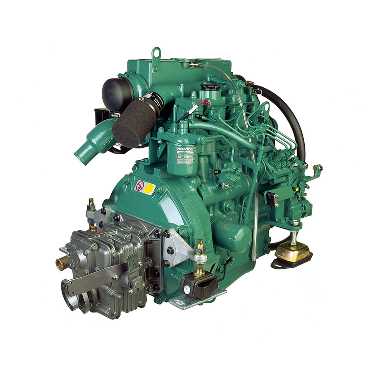
Volvo 3TNV76 Operating and installation instructions

Service Information
Document Title: Function Group: Information Type: Date:
Engine, description 200 Service Information 2014/4/14
Profile:
CEX, ECR28 [GB]
Engine, description
Model code (3TNV76)
Model code
Symbol Description Remarks
3 Number of cylinders
TNV Model series
76 Cylinder bore (mm)
The engine is a 3–cylinder, indirect injected, water cooled diesel engine.
Engine, front view
Figure 1
Engine, front view
1.
2.
3.
4.
5.
6.
7.
8.
9.
10.
11.
12.
13.
14.
15.
16.
17.
18.
Lifting eye
Cooling water pump
Lifting eye
Fan
V-belt
V-pulley
Filler port (lube oil)
Fuel oil inlet
Drain plug (lube oil)
Mechanical fuel feeding pump
Fuel priming lever
Dipstick
Oil filter
Governor lever
Fuel injection pump
Intake manifold
Fuel filter
Air intake port

Engine, rear view
Figure 2
Engine, rear view
1.
2.
3.
4.
5.
6.
7.
Filler port (lube oil)
Bonnet (rocker arm cover)
Engine name plate
Flywheel
Starter motor
Exhaust manifold
Alternator

Service Information
Document Title: Function Group: Information Type: Date:
Precautions 200 Service Information 2014/4/14
Profile:
CEX, ECR28 [GB]
Precautions
Make preparation as follows before starting engine inspection and service.
Fix the engine on a horizontal base.
Remove the coolant hoses, fuel oil pipes, wire harness, control wires etc. connecting the driven machine and
engine, and drain coolant, lubricating oil and fuel.
Remove soil, oil, dust, etc. from the engine by washing with solvent, air, steam, etc. Carefully operate so as not to let
any foreign matter enter the engine.
Any part which is found defective as a result of inspection or any part whose measured value does not satisfy the
standard or limit shall be replaced.
Any part predicted to dissatisfy the standard or limit before the next service as estimated from the state of use
should be replaced even when the measured value then satisfies the standard or limit.

Service Information
Document Title: Function Group: Information Type: Date:
Periodic inspection and
maintenance procedure
200 Service Information 2014/4/14
Profile:
CEX, ECR28 [GB]
Periodic inspection and maintenance procedure
Check before daily operation
Be sure to check the following points before starting the engine every day.
Visual check around engine
Oil leak from the lubrication system
Fuel leak from the fuel system
Cooling water leak from the cooling water system
Damaged parts
Loosened or lost bolts
Fuel, radiator rubber hoses, V belt cracked, loosened clamp
Fuel tank level check and fuel supply
Check the remaining fuel oil level in the fuel tank and refuel the recommended fuel if necessary.
Lube oil level check and replenishment
Checking oil level.
Check the engine oil level with the dipstick, after adjusting the posture of the machine unit so that the engine is
level. Insert the dipstick fully and check the oil level. The oil shall not be contaminated heavily and have appropriate
viscosity. No coolant or diesel oil shall be mixed.
The level shall be between the upper and lower limit lines on the dipstick.
Figure 1
Checking oil level and replenishing with engine oil
1.
2.
3.
4.
Filler port (lube oil)
Dipstick
Upper limit
Lower limit
Engine oil capacity, unit: liter (gal.)
Total volume Effective volume

3.5 (0.92) 1.6 (0.42)
Replenishing oil pan with engine oil.
If the remaining engine oil level is low, fill the oil pan with the specified engine oil to the specified level through the
filler port.
NOTE!
The oil should not be overfilled to exceed the upper limit line. Otherwise, oil may jet out from the breather or the
engine may become faulty.
Coolant inspection
Daily inspection of the coolant should be done only by sub-tank.
WARNING
Risk of scalding and burns when the expansion tank cap (radiator cap) is opened due to high pressure in the cooling
system.
WARNING
Risk of scalding and burns when the expansion tank cap (radiator cap) is opened due to high pressure in the cooling
system.
WARNING
Before removing the radiator cap, stop the engine and let it cool down sufficiently. When removing it, turn it slowly
to release the pressure.
NOTE!
Securely tighten the filler cap after checking the radiator. Steam can spurt out during operation, if the cap is not properly
tightened.
Checking coolant volume
Check the coolant level in the sub-tank. If the water level is close to the LOW mark, open the sub-tank cap and
replenish the sub-tank with clean soft water or premix to the FULL mark.
The coolant level of the sub-tank shall be between the upper and lower limit lines.
Figure 2
Checking, coolant level in the sub-tank
A.
B.
C.
Sub-tank
Upper limit
Lower limit
Replenishment engine with coolant
If the sub-tank coolant level is lower than the LOW mark, open the radiator cap and check the coolant level in the
radiator. Replenish the radiator with coolant, if the level is low.
Check the coolant level while the engine is cool. Checking when the engine is hot is dangerous. And the
coolant volume is expanded due to the heat.

Daily coolant level check and replenishing shall be done only at the sub-tank. Usually do not open the
radiator cap to check or replenish.
Figure 3
Replenishment, coolant
A.
B.
C.
Tighten
Loosen
Radiator cap
NOTE!
If the coolant runs short quickly or when the radiator runs short of coolant with the sub-tank level unchanged, coolant may
be leaking or the air tightness may be lost. Increase in the sub-tank level during operation is not abnormal. The increased
coolant in the sub-tank returns to the radiator when the engine is cooled down. If the level is normal in the sub-tank but low
in the radiator, check for loosened clamping of the rubber hose between the radiator and sub-tank or a tear in the hose.
Engine: The radiator shall be filled up.
Coolant capacity, unit: liter (gal)
Coolant volume in the engine
0.9 (0.23)
Fuel pipe and cooling water pipe inspection and maintenance
Check the rubber hoses for fuel and cooling water pipes cracked. If the cracked hose is found, replace it with new one. Check
the loosened clamp. If found, tighten it.
Warning lamp & instruments function check
Before and after starting the engine, check to see that the alarm function normally. Failure of alarm cannot warn the lack of
the engine oil or the cooling water. Make it a rule to check the alarm operation before and after starting engine every day.
Checking accelerator operation
Make sure the accelerator of the machine unit can be operated smoothly before starting the engine. If it feels heavy to
manipulate, lubricate the accelerator cable joints and pivots. Adjust the accelerator cable if there is a dislocation or excessive
play between the accelerator and the governor lever.
Inspection after initial 50 hours operation
WARNING
Hot oil and hot engine coolant can cause severe burns!
NOTE!
Replace engine oil after the engine oil becomes warm. It is most effective to drain the engine oil while the engine is still
warm.
In early period of use, the engine oil gets dirty rapidly because of the initial wear of internal parts. Replace the engine oil
earlier. Engine oil filter should also be replaced when the engine oil is replaced. Engine oil and engine oil filter replacing
procedures are as follows. Remove the oil filler cap to drain easily while draining the engine oil.
Drain engine oil
Prepare a waste oil container collecting waste oil.
Remove the drain plug using a wrench to drain the engine oil.
Securely tighten the drain plug after draining the engine oil.

Figure 4
Dipstick gauge, oil pan and drain plug
1.
2.
3.
4.
5.
Dipstick
Oil filler cap
Oil filter
Oil pan
Drain plug
Replacing oil filter
Turn the engine oil filter counterclockwise using a filter wrench to remove it.
Clean the mounting face of the oil filter.
Moisten the new oil filter gasket with the engine oil and install the new engine oil filter manually turning it
clockwise until it comes into contact with the mounting surface, and tighten it further to 3/4 of a turn with
the filter wrench.
Tightening torque: 2.0 ~ 2.4 kgf·m (14.4 ~ 17.3 lbf·ft).
Applicable oil filter part number: 119305-35150.
Figure 5
Replacement, engine oil filter
A.
B.
Loosen
Tighten

C. Engine oil filter
Filling oil and inspection
NOTE!
Do not overfill the oil pan with engine oil. Be sure to keep the specified level between upper and lower
limit on the dipstick.
Warm up the engine by running for 5 minutes while checking any oil leakage.
Stop the engine after warming up and leave it stopped for about 10 minutes then recheck the engine oil
level with dipstick and replenish the engine oil. If any oil is spilled, wipe it away with a clean cloth.
Checking and adjusting radiator fan V-belt
When there is not enough tension in the V-belt, the V-belt will slip making it impossible for the alternator to generate power
and water pump and cooling fan will not work causing the engine to overheat. Check and adjust the V-belt tension
(deflection) in the following manner.
Press the V-belt with your thumb [approx. 98N (10kgf)] at the middle of the V-belt span to check the tension
(deflection).
Available positions to check and adjust the V-belt tension (deflection) are at the A, B or C direction as shown in the
illustration right.
You may choose a position whichever you can easily carry out the check and adjustment on the machine unit.
"New V-belt" refers to a V-belt which has been used less than 5 minutes on a running engine.
"Used V-belt" refers to a V-belt which has been used on a running engine for 5 minutes or more.
The specified deflection to be measured at each position should be as follows.
Figure 6
Checking and adjustment, radiator fan V-belt
1.
2.
3.
4.
5.
6.
7.
Radiator fan
V-belt
Crankshaft V-pulley
Press with thumb
Deflection
Alternator
Set screw
V-belt deflection, unit: mm (in)
Direction A B C
For used V-belt 10 ~ 14
(0.39 ~ 0.55)
7 ~ 10
(0.28 ~ 0.39)
9 ~ 13
(0.35 ~ 0.51)
For new V-belt 8 ~ 12
(0.31 ~ 0.47)
5 ~ 8
(0.20 ~ 0.31)
7 ~ 11
(0.28 ~ 0.43)

If necessary, adjust the V-belt tension (deflection). To adjust the V-belt tension, loosen the set screw and move the
alternator to tighten the V-belt.
After replacing with a new V-belt and adjusting it, run the engine for 5 minutes and readjust the deflection to the
value in the table above.
Visually check the V-belt for cracks, oiliness or wear.
If any, replace the V-belt with a new one.
Figure 7
Adjustment, V-belt tension
A.
B.
C.
Bar
Adjuster
Alternator
Inspection 50 hours
Be sure to check the following points every 50 hours operation.
Draining of the fuel tank
Figure 8
Draining, fuel tank
1.
2.
3.
Fuel tank
Drain plug
Oil container

Prepare a waste oil container.
Turn the drain cock valve of the fuel tank to drain (water, dirt, etc.) from the fuel tank bottom.
Drain until fuel with no water and dirt flow out. Then tighten the drain cock valve firmly.
Draining of the oil/water separator
Figure 9
Draining, oil/water separator
1.
2.
3.
4.
5.
Air bleeding screw
Float ring
Retaining spring
Retaining ring
Fuel cock
A.
B.
C.
D.
Inlet
Outlet
Close
Open
Drain off the oil/water separator whenever there is a lot of drain collected in the oil/water separator at the bottom of the
cup even if not the time for periodic inspection hour. The cup of the oil/water separator is made from semi-transparency
material and in the cup, the red colored float ring which rises on the surface of the drain is installed to visualize the amount
of drain. Also, the oil/water separator with a sensor to detect the drain for warning device on the control panel is provided as
an option.
Drain off the oil/water separator in the following manner.
Close the fuel cock.
Loosen the retainer ring, and remove the cup, then throw collected water and trash away.
Put a float ring and a spring in the cup and tighten the retainer ring.
Tightening torque: 13 ~ 16 Nm (1.3 ~ 1.6 Kgf.m).
Be sure to bleed off any air in the fuel system.
Bleeding the fuel system

Figure 10
Bleeding, fuel system
1.
2.
3.
4.
5.
6.
7.
8.
9.
Fuel filter
Fuel return hose
Fuel injection pump
Mechanical fuel feed pump
Priming lever
Air bleeding screw
Fuel cock
Retaining ring
Joint for fuel return
A.
B.
C.
D.
E.
Inlet
Outlet
Close
Open
From oil/water separator
Bleed the fuel system according to the following procedures. When there is air in the fuel system, the fuel injection pump
will not be able to function.
Check the fuel oil level in the fuel tank. Refuel if insufficient.
Open the cock of the oil / water separator.
Loosen the air bleeding screw on the oil /water separator by turning 2 ~ 3 times to the counterclockwise using a
screw driver or spanner.
When the fuel coming out is clear and not mixed with any air bubbles, tighten the air bleeding screw.
Feed the fuel with the fuel priming pump or electro-magnetic fuel feed pump.
In case of the engine using the electro-magnetic fuel feed pump. Turn the starter switch to the ON
position and hold it in the position for 10 ~ 15 seconds to operate the fuel feed pump.
Move the priming lever by hand up and down, and feed fuel until the fuel surface inside the fuel filter cup
goes up and the air disappears inside. (Move the lever until feeling your hand slightly heavy).
Don't do air bleeding by a starting motor.
Battery inspection
NOTE!
Fire due to electric short-circuit

Make sure to turn off the battery switch or disconnect the negative cable (–) before inspecting the electrical system.
Failure to do so could cause short-circuits and fires.
Always disconnect the (–) Negative battery cable first before disconnecting the battery cables from battery. An
accidental "Short circuit" may cause damage, fire and or personnel injury. And remember to connect the (–)
Negative battery cable (back onto the battery) LAST.
NOTE!
Proper ventilation of the battery area
Keep the area around the battery well ventilated, paying attention to keep away any fire source. During operation
or charging, hydrogen gas is generated from the battery and can be easily ignited.
NOTE!
Do not come in contact with battery electrolyte
Pay sufficient attention to protect your eyes or skin from being in contact with the fluid. The battery electrolyte is
diluted sulfuric acid and causes burns. Wash it off immediately with a large amount of fresh water if you get any on
you.
Battery structure
Figure 11
Structure, battery
1.
2.
3.
4.
5.
6.
7.
8.
Terminal
Cap
Cover
Cathode plate
Separator
Glass mat
Anode plate
Battery case
Electrolyte level

Figure 12
Checking, electrolyte level
1 OK
2 Too low
3 Excessive
A Grease
B Upper limit
C Lower limit
D Electrolyte level
Check the level of fluid in the battery.
When the amount of fluid nears the lower limit, fill with battery fluid (available in the market) to the upper limit. If
operation continues with insufficient battery fluid, the battery life is shortened, and the battery may overheat and
explode.
Battery fluid tends to evaporate more quickly in the summer, and the fluid level should be checked earlier than the
specified times.
If the engine cranking speed is so slow that the engine does not start up, recharge the battery.
If the engine still will not start after charging, replace the battery.
Remove the battery from the battery mounting of the machine after daily use if leaving the machine in a place that
the ambient temperature could drop at -15 °C (5 °F)or less. And store the battery in a warm place until the next use,
to start the engine easily at low ambient temperature.
Battery charge
Use a battery tester or hydrometer and check the battery condition. If the battery is discharged, recharge it.
Measurement with a battery tester

Figure 13
Measurement, battery charge
1. Tester
When checking the battery with the batter tester, connect the red clip of the tester to the battery positive (+) terminal and
black clip to the battery negative (–) terminal by pinching them securely, and judge the battery charge level from the
indicator position.
Green zone: Normal
Yellow zone: Slightly discharged
Red zone: Defective or excessively discharged
Measurement with hydrometer
Figure 14
Measurement, battery charge
1. Float
When using a hydrometer, the measured specific gravity must be corrected according to the temperature at the time of
measurement. The specific gravity of battery electrolyte is defined with 20 C (68 °F) as the standard. Since the specific gravity
increases or decreases by 0.0007 when the temperature varies by 1 C (33.8 °F), correct the value according to the equation
below.
S20 = St + 0.007 (t-20)
where to,
S20 = Converted specific gravity at 20 C (68 °F)
St = Specific gravity at measurement
t = Electrolyte temperature at measurement
Figure 15
Hydrometer structure

1.
2.
3.
Rubber bulb
Glass tube
Float
Figure 16
How to read hydrometer
Specific gravity and remaining battery charge
Specific gravity (20 °C) Discharged quantity of electricity (%) Remaining charge (%)
1.28 0 100
1.26 10 90
1.24 20 80
1.23 25 75
Terminals
Clean if corroded or soiled.
Mounting bracket
Repair or replace it if corroded.
Retighten if loosened.
Battery appearance
Replace the battery if cracked or deformed.
Clean with fresh water if contaminated.
Inspection every 250 hours or 3 months
Be sure to check the following points every 250 hours or 3 months operation, whichever comes first.
Oil and filter replacement (The second replacement and after)
Replace the engine oil every 250 hours operation from 2nd time and
Replace the engine oil filter at the same time.
Inspection and cleaning of radiator fin

Figure 17
Inspection and cleaning, radiator fin
1 Radiator fin
2 Air blow
A Dust, dirt
Dirt and dust adhering on the radiator fins reduce the cooling performance, causing overheating. Make it a rule to check the
radiator fins daily and clean as needed.
Blow off dirt and dust from fins and periphery with compressed air 2 kgf/cm2 (28 psi) or less] not to damage the fins with
compressed air.
If contaminated heavily, apply detergent, thoroughly clean and rinse with tap water shower.
NOTE!
Wear protective equipment such as goggles to protect your eyes when blowing compressed air. Dust or flying debris can
causes eye injury.
NOTE!
Do not use high pressure water or air close to the fins or do not attempt to clean using a wire brush. Radiator fins can be
damaged.
Checking and adjusting radiator fan V-belt
Check and adjust the V-belt tension. (See Inspection initial after 50 hours, checking and adjusting radiator fan V-belt).
Adjustment of governor lever and accelerator device
Figure 18
Adjustment, governor lever and accelerator device
1.
2.
3.
4.
High idle limiting screw
Governor lever
Accelerating wire bracket
Low idle limiting screw

The governor lever and accelerating devices (accelerating lever, pedal, etc.) of the machine unit are connected by an
accelerating cable or rod. If the cable becomes stretched or the connections loosen, deviation in the position may result and
make operation unsafe. Check the cable periodically and adjust if necessary. Do not strongly move the accelerating cable or
accelerating pedal. It may deform the governor lever or stretch the cable to cause irregular engine speed control. Checking
and adjusting procedure are as follows:
Check that the governor lever of the engine makes uniform contact with the high idling and low idling limiting
screw when the accelerating device is in the high idling speed or low idling speed position
If either the high or the low idling speed side does not make contact with the limiting screw, adjust the accelerating
cable. Loosen the accelerating cable fixing nut and adjust the cable to contact the limiting screw.
NOTE!
Do not release the limiting screws. It will impair the safety and performance of the product and functions and result in
shorter engine life.
Air cleaner element cleaning
Figure 19
Cleaning, air cleaner element (double type)
1.
2.
3.
4.
5.
6.
Dust indicator (optional)
Air cleaner case
Inner element
Outer element
Dust pan
Air blow
The engine performance is adversely affected when the air cleaner element is clogged by dust. So periodic cleaning after
disassembly is needed.
NOTE!
Wear protective equipment such as goggles to protect your eyes when blowing compressed air. Dust or flying debris can
causes eye injury.
Undo the clamps on the dust pan and remove the dust pan.
Pull out the outer element.
Blow air 3.0 ~ 5.0 kgf/cm2 (43 ~ 71 psi) from inside the element to blow dust off as shown in the illustration left
Apply the air blowing pressure as low as possible so as not to damage the element.
If having the air cleaner with double elements, do not remove and clean the inner element.
The aim of installing the inner element is for back up protection when the outer element is unexpectedly damaged
during engine running.

Replace the element with new one, if the element is damaged, excessively dirty or oily.
Install the dust pan to the air cleaner case placing the TOP mark upward.
NOTE!
When the engine is operated in dusty conditions, clean the element more frequently. Do not run the engine with air cleaner
or element removed, as this may cause foreign material to enter and damage the engine.
Inspection every 500 hours or 6 months
Be sure to check the following points every 500 hours or 6 months operation, whichever comes first.
Air cleaner element
Replace the air cleaner element periodically even if it is not damaged or dirty. When replacing the element, clean inside of
the dust pan at the time. If having the air cleaner with double elements, do not remove the inner element. If the engine
output is still not normal (or the dust indicator still actuates if having the air cleaner with a dust indicator) even though the
outer element was replaced with a new one, replace the inner element with a new one.
Fuel filter element
Figure 20
Replacement, fuel filter
1.
2.
3.
4.
5.
6.
7.
8.
9.
Fuel filter
Fuel return hose
Fuel injection pump
Mechanical fuel feed pump
Priming lever
Air bleeding screw
Fuel cock
Retaining ring
Joint for fuel return
A.
B.
C.
D.
E.
Inlet
Outlet
Close
Open
From oil/water separator
Replace the fuel filter at specified intervals before, it is clogged with dirt to adversely affect the fuel flow. Also, replace the
fuel filter after the engine has cooled.

Close the fuel filter cock.
Loosen the retaining ring and replace the fuel filter element. Take the water and trash in the cup out. When
removing the fuel filter with a piece of rag to prevent the fuel oil from dropping. If you spill fuel, wipe such spillage
carefully.
Install the new fuel filter element and tighten the retainer ring.
Tightening torque: 1.3 ~ 1.6 kgf·m (9.4 ~ 11.5 lbf·ft)
Applicable fuel filter part no.: 119740-55650
Bleed the fuel system.
NOTE!
Be sure to use genuine Yanmar part (super fine mesh filter). Otherwise, it results in engine damage, uneven engine
performance and shortened engine life.
Cleaning oil/water separator
Figure 21
Draining, oil/water separator
1.
2.
3.
4.
5.
Air bleeding screw
Float ring
Retaining spring
Retaining ring
Fuel cock
A.
B.
C.
D.
Inlet
Outlet
Close
Open
The cup of a water separator is translucent, and the inside can be seen. The float ring rises when water collects at the bottom
of the cup. Periodically wash the water separator and inside cup with clean fuel oil.
Close the fuel cock.
Loosen the retaining ring and remove the cup. Take the water and trash in the cup out.
Wash the element and inside cup with clean fuel oil. Replace the element with a new one if any damage.
Applicable fuel filter part no.: 129335-55700
Insert the element to the bracket and after putting the float ring in the cup, install it to the bracket by tightening
the retaining ring.
Tightening torque: 1.3 ~ 1.6 kgf·m (9.4 ~ 11.5 lbf·ft)
Bleed the fuel system.
Inspection every 1000 hours or one year
Be sure to check the following points every 1000 hours or one year operation, whichever comes first.
Replacing coolant

Figure 22
Coolant, replacement
1 Radiator cap
2 Rubber hose
3 Sub-tank
4 Drain plug
A Full (max limit)
B Low (min limit)
WARNING
Risk of scalding and burns when the expansion tank cap (radiator cap) is opened due to high pressure in the cooling
system.
WARNING
Before removing the radiator cap, stop the engine and let it cool down sufficiently. When removing it, turn it slowly
to release the pressure.
Coolant contaminated with rust or water scale reduces the cooling effect. Even when antifreeze agent (LLC) is mixed, the
coolant gets contaminated due to deteriorated ingredients. Replace the coolant at least once a year.
Remove the radiator cap.
Loosen the drain plug at the lower portion of the radiator and drain the coolant.
After draining the coolant, tighten the drain plug.
Fill radiator and engine with coolant.
Diaphragm inspection
Table of contents
Other Volvo Engine manuals

Volvo
Volvo 5.0OSiE-J User manual

Volvo
Volvo D1-13 B Instruction manual

Volvo
Volvo TAD650VE Instruction manual

Volvo
Volvo KAD44P User manual

Volvo
Volvo DH10A 245 User manual

Volvo
Volvo D20 User manual

Volvo
Volvo B 17 User manual

Volvo
Volvo D4 User manual

Volvo
Volvo TAD734GE User manual

Volvo
Volvo B27A User manual
Popular Engine manuals by other brands

VOLTRIUM
VOLTRIUM Rogue Dual Motor Series owner's manual

BAFANG
BAFANG H300 user manual

Husqvarna
Husqvarna Kohler SV470 Workshop manual

Aluprof
Aluprof ER-P Series Programming manual

Motorisation+
Motorisation+ RUN24 Instructions and warnings for installation and use

DR
DR R100 Safety and operating instructions