manuals.online logo
Brands
  1. Home
  2. •
  3. Brands
  4. •
  5. Volvo
  6. •
  7. Engine
  8. •
  9. Volvo D20 User manual

Volvo D20 User manual

Other manuals for D20

2

This manual suits for next models

1

Other Volvo Engine manuals

Volvo D16F Reference manual

Volvo

Volvo D16F Reference manual

Volvo TAD734GE User manual

Volvo

Volvo TAD734GE User manual

Volvo B16B Setup guide

Volvo

Volvo B16B Setup guide

Volvo MB10A Instruction manual

Volvo

Volvo MB10A Instruction manual

Volvo DH10A 245 User manual

Volvo

Volvo DH10A 245 User manual

Volvo B 17 User manual

Volvo

Volvo B 17 User manual

Volvo B 17 User manual

Volvo

Volvo B 17 User manual

Volvo TAD1240GE User manual

Volvo

Volvo TAD1240GE User manual

Volvo B5254T3 User manual

Volvo

Volvo B5254T3 User manual

Volvo TD420VE User manual

Volvo

Volvo TD420VE User manual

Volvo 819 E User manual

Volvo

Volvo 819 E User manual

Volvo D4 User manual

Volvo

Volvo D4 User manual

Volvo D13F User manual

Volvo

Volvo D13F User manual

Volvo KAD44P User manual

Volvo

Volvo KAD44P User manual

Volvo XC90 - ANNEXE 951 User manual

Volvo

Volvo XC90 - ANNEXE 951 User manual

Volvo MD2010 Instruction manual

Volvo

Volvo MD2010 Instruction manual

Volvo 2001 User manual

Volvo

Volvo 2001 User manual

Volvo D13 User manual

Volvo

Volvo D13 User manual

Volvo TAMD74C User manual

Volvo

Volvo TAMD74C User manual

Volvo TAD650VE Instruction manual

Volvo

Volvo TAD650VE Instruction manual

Volvo B6324S Operating and installation instructions

Volvo

Volvo B6324S Operating and installation instructions

Volvo D13H User manual

Volvo

Volvo D13H User manual

Volvo D9 series User manual

Volvo

Volvo D9 series User manual

Volvo TAMD75P User manual

Volvo

Volvo TAMD75P User manual

Popular Engine manuals by other brands

Nakanishi EM-3030T Operation manual

Nakanishi

Nakanishi EM-3030T Operation manual

Siemens COMBIMASTER CM12 operating instructions

Siemens

Siemens COMBIMASTER CM12 operating instructions

Bosch Rexroth Hagglunds CA Series Installation and maintenance manual

Bosch

Bosch Rexroth Hagglunds CA Series Installation and maintenance manual

Hyundai H170VC manual

Hyundai

Hyundai H170VC manual

Graco 273199 repair parts

Graco

Graco 273199 repair parts

MOTO GUZZI BREVA V1100 Workshop manual

MOTO GUZZI

MOTO GUZZI BREVA V1100 Workshop manual

Dualsky Track & Field Z5 instruction manual

Dualsky

Dualsky Track & Field Z5 instruction manual

Rotax 125 senior MAX evo installation manual

Rotax

Rotax 125 senior MAX evo installation manual

Kohler K361 Service manual

Kohler

Kohler K361 Service manual

MTD OHV Series user guide

MTD

MTD OHV Series user guide

Mercury D4.2L D-Tronic manual

Mercury

Mercury D4.2L D-Tronic manual

Perkins 1206E-E66TA Operation and maintenance manual

Perkins

Perkins 1206E-E66TA Operation and maintenance manual

Skov DA 174 Technical user guide

Skov

Skov DA 174 Technical user guide

Rotax 915 i A SERIES Maintenance manual

Rotax

Rotax 915 i A SERIES Maintenance manual

AL-KO PRO 350 Instructions for use

AL-KO

AL-KO PRO 350 Instructions for use

MTU 12 V 4000 Lx4 operating instructions

MTU

MTU 12 V 4000 Lx4 operating instructions

Nanni N3.30 Workshop manual

Nanni

Nanni N3.30 Workshop manual

Nanni N5.160 CR2 Operator's manual

Nanni

Nanni N5.160 CR2 Operator's manual

manuals.online logo
manuals.online logoBrands
  • About & Mission
  • Contact us
  • Privacy Policy
  • Terms and Conditions

Copyright 2025 Manuals.Online. All Rights Reserved.

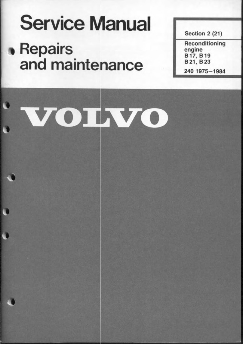
Service
Manual
Repairs
and
maintenance
Section
2(21)
Reconditioning
engine
020,024
1979-19
..
.
D 20,
024
80th
the D 20
and
D
24
Diesel
engines
are
deall
with
in
this
manual.
The D
20
has
fi"e
cylindersand the D
24
six. Dtherwisethe engines are
similar
in principle.
Natel
Different
flywheels
and
vibration
dampers
are
fitted
to the
different
engine types.
020 024
Volvos are sold in versions adapted for
different
markets. These
adaptations
depend on
many
fae-
tars
including
legal, taxation and
market
require-
ments.
This
manual
may
therefore
show
illustrations
and
text
which
do
not
apply
to
cars in
your
country.
•
128642
•
•l
l
Contents
Important
information
.....
....
...
..
..................................................................................
...
.
Specifications
..............................
.......
................................................................................
.
Page
2
3
Special
tool.
....................
...
.......
.......
...
.
...
.
...
.....
..
..
...
.
...........................................................
16
Reconditioning engine
Removing parts
from
engine ..................................................
Disassembly ............................
...
.............................................
Cleaning, checking ..................................................................
Aeassembly .............................................................................
Cylinderhead, assembly .....................................
..
.................
cleaning, checking ....................................................
reassembJy ..............................
..
...............................
installation ................................................................
Installation, (cont.) ..................................................................
Installing parts
on
engine .
...
...................................................
Index
page
74
Operation
Al-15
Bl-18
C
l-28
Dl-30
El-l1
Fl
-2l
Gl-14
Hl-8
Jl-20
Kl-27
This manual deals exclusively
with
the overhaul
of
the engine. For
work
carried
out
on the engine
when
fitted
in
the
ear,
and
for
engine removal and
installation, please reter
to
the service manual Sec-
tion
2(20-22)
and Section 2(23-29).
TP
30224
/2
US
UK
/USA
6000.05.83
PRINTED
IN
USA
We
reser
ve
the
right
to
make alterations
l.
24
2.
36
43
46
51
55
5.
65
1
2
Important
information
,,,
.
..
Nm
135020
ClEANLlNESS
Diesel injection systems are extremely sensitive
to
dirt
and
foreign
malter.
A special
workplace
should
there-
fore be used
for
inspection of components.
PWGS
Clean
fuelline
co
nn
ec
tion
s
thoroughly
befare
discon
-
•
•
necting
them.
Plug
ends
of
fuellines
etc as each
com-
•
ponent is removed. Do
not
remove these
plugs
unl
il
the component is reconnected.
Tightening
torques
Two kinds
of
tightening
torques
will
be
found
in
this
manual
1. Ti
ghten
to
40
Nm
(30
fl
Ibs) indicates
that
a
torque
wrench
must
be used
for
tightening.
2.
Tight
ening
torque
40
Nm
(30
ft
Ibs) indicates a
guide
va
lue.
Tight
en
ing
need
not
be
done
with
a
torque
wrench.
VW
type
designation
[
Specifications
Specifications
Group
20 General
_=--=--=-
..
J
Engine
number
VOLVO
type
designation
'33 7
51
Engine
type
designation and serial number
Stamped in
left
side
of
cylinder
block
beneath vacuum
pump.
3
Specifications
Group
21
Engine
block
CYLINDER HEAD
0.5
mm = 0.020 in
Diagonally = max
0.5
mm :lO 0.020 in
Cylinder
head
may
not
be
machined.
It
must
be
replaced
if
warp
exceeds
maximum
.
Cylinder head gaskat
0.2
mm
""
0.0
08
in
I,
128
141
Crosswise = max 0
.2
mm = 0.008 in
Thrae alternative gaskets are u
se
d depending
on
height
of
piston above cylinder block.
Marked by notch
~
,
,.
".
4
Height
of
piston
above
Gasket
cylinder
block
notehes
thickness
mm
in
mm
in
0.67-0.80
0.026-0.031
1 L' 0.055
0.81-0.90
0.032-0.035
2 1.5 0.059
0.91-1.02
0.036-0.040
3 1.6 0.063
Notel
Piston
height
in
same
engine
must
not
extend
over
more
than
two
classes. Pis
ton
height
is
measured
at
front
and
back
of
piston
(along
gudgeon
/
piston
pin).
•
$pecifications
CYLINDER BLOCK
Bore
Mark
i
ng
Piston
diameter
Cylinder
bore
mm
Standard
............
..
..
..
..................
651
76
.48
652 76.49
653 76.
50
Oversize 1 ................................... 676 76.73
(0.25
mm
=0.010 in) 677 76.74
678 76.75
Oversize2
...................................
701
76.98
(0.50
mm
=0.020 in) 702 76.99
703 77.00
Oversize 3
....................
751
71.48
(1.00
mm
=0.040 in) 752 77.49
753 77.50
Mo<
weaT
dimension
(compared
with
normal
diameter)
PISTONS
Weight (inel.
gudgeon
/piston pin) .............................................
Max
weight
deviation
between
pistons
in same engine ...........
Overall
height
.............................................................................
Height
from
gudgeon
/
piston
pin
center to piston
crown
.........
Piston float,
new
............................................
...
.
..
.......................
max .........................................................................
Piston diameter, see
cylinder
bare table
Wear di
mension,
max
(compared
with
normal
diameter) ........
;n
mm
3.0110 76.51
3.0114 76.52
3.0118
76
.
53
3.0209 76.76
3.0212 76.71
3.0217 76.78
3.0307
71
.
01
3.0311 77.02
3.0315 77.03
3.0504
77.51
3.0508 77.52
3.0512
77
.
53
0.04
mm
455-465
grammes
12
grammes
71.7
mm
41.7
mm
0.03-0.05
mm
0.13
mm
0.04
mm
;n
3.0122
3.0125
3.0130
3.0220
3.0224
3.0228
3.0318
3.0322
3.0326
3.0515
3.0519
3.0523
0.016 in
2.8228 in
1.6417 in
0.0051 in
0.0016
in
Piston
rings
Piston ring gap is measured
15
mm
(0.6
in
from
lower
edge
of
cylinder).
Piston
diameter
is measured at
right
angles to
gudgeon
l
piston
pin
bore,
15
mm
(0.6 in)
from
lower
edge. o
Ring thickness ................... ................................................
mm
Side clearance
(measured
with
ring on pisten), new .................................
mm
;n
max
................................
mm
Ring gap
(measured in cylinder, see fig.),
new
.................................
mm
;n
max
...
..
..
..
.
..
....................
mm
Gudgeon/piston
pins
Fit, in
connecting
rad .................
...
..........................................
in pisten .............................
..
.........................................
..
...
...
-~
~
t
_
J
• '
>O
.
..
Upper
Lewer
Oil
seraper
compression
eompression
ring
ring ring
1.730 1.980-1.990
2.975-2.990
0.0681
-0.0685
0.0780-0.0783 0.1171
-0.1171
0.06-0.09
0.05-0.08
0.03-0.06
0.0024-0.0035 0.0020-0.0031 0.0012-0.0024
0.2 0.2 0.15
0.0079 0.0079 0.0059
0.3-0.5 0.3-0.5
0.25-0.40
0.012-0.020
0.012-0
.020 0.0098-0.0157
1.0 1.0 1.0
0.040 0.040 0.040
Light
thumb
pressure (close
running
fit)
Thumb
pressure (push
fit)
5
Specifications
VALVE SYSTEM
Valve clearances
D20
Intake
va
lve,
warm
engine
...........................................
c
old
engine
.............................................
Exhaust valve,
warm
engine
.....................
...
................
cold
engine
..........................................
Shims,thickness ..........................................................
VIIyes
7.97
mm
= 0.3137
in
36
mm
-1.417
in
0.5
mm
= 0.020
in
7.97 mm
.
(tlJ)
---..I~~I-_mi".
0.5
mm
Vllye
seats
32.8
mm
"" 1.2193
in
1.5
mm
= 0.0590
in
2.0
mm
==
0.787
in
Intake Yllye
,
32.8
nm
Intake
YI
lye
selt
,331,
.
\33J!.II
Cold engine =
engine
at
r
oo
m
temperature
= intake valves
A = exhaust valves
Checkladjust valves in foll
owing
order:
020 = '-2-4-5-3
024
= ' -5-3-6-2-4
Checking
Setting
mm
;"
mm
0.20-
0.30 0.
008-0.012
0.25
0.1
5-
0.25 0.006- 0.010 0.20
0.40-0.50
0.016-0.020
0.45
0.35-0.45
0.014-0.018
0.40
3.00-4.25
at
increments
of
0.05
mm
0.012-0.167
at
increments
of
0.002
in
7.95
mm
= 0.3129 in
31
mm
'"
1.22 in
45'
7.95 mm
Exhaust
y.lye
;n
0.010
0.008
0.018
0.Q16
131115
Importanti
Exhaust valves are stellite coated and
must not
be
ground
by machine. Grind-in valve on
seat
with
grinding
paste.
30.4
mm
= 1.1968 in
1.5
mm
= 0.0590 in
2.4
mm
= 0.094
in
30
.4
nm
Exhlust
y.lye
selt
1:13159
Exhaust
Valve seat
diameter
,
standard
............................................
mm
Intake
37.090-37.105
1.4602
-1.
4608
37.
290-37.305
1.4681- 1.4687
33.090-33.105
1.3027-1.3033
33.290-33.305
1.3106-1.3112
oversize 1
..
........................................
mm
Seat
width
in
cylinder
head:
diameter, standard ..............................................................
mm
oversize 1 .......................................................
...
..
mm
;n
6
37.000-37.016
1.4566-1.4573
37.200-37.216
1.
46
45-
1.4651
33.000-33
.016
1.2992-1.2998
33.200-33.216
1.
3070-1.3071
•
Specifications
1~·
(OoO~r00105
mm)
Notel When replacing
"al"e
seats: the interference between
the
"al"e
seat and its bare
in
the
cylinder
head shall be
0.074-
0.105
mm
(0.029-0.041 ini. That is.
"a
l"e
seat
diameter
must
be
0.074-0.105
mm
greater than the
diameter
of
the bore in the
cylinder head. -
......
Valve guides
mm
(ini
:-.
Length
...
......................................................
...
.............................
Innerdiameter ............................................................................
Height abo"e cylinder head
lower
surface ..............................
..
Clearance,
"al"e
stem-guide (see fig.l.
new
............................
..
max ..............................
Clearance is measured
with
new
"al"e
and
with
"al"e
stem
flush
with
"al"e
guide.
Valve
springs
Inner valve springs
Load
N
Ib,
36.50-36.75
(1.4370-1.4468)
8.000-8.015
(0.3
149-0.3155)
40.1
-40.5
(1.5787
-1.59
44)
0.3 (0.018)
1.3 (0.0511)
Outer
valve springs
Load
In
N
OO
M
Ib,
Length
mm
33.9
28.6
18.3
In
1.334
1.126
0.720
O
67-77
209-231
O
15-17.5
47-52.2
Length
mm
40.2
32.6
22.3
1.583
1.283
0.878
O
167-185
433-479
O
38-42
98-108
Tappets
Diameter ...........................................................................
..
.
Height........................................................................................
..
Clearance.
sh
im
-tappet ..............................................................
tappet-cylinder head ................................................
Shims
(for
adjusting
"al"8
clearance)
Thickness ...................................................................................
Diameter .....................................................................................
34.950-34.975
(1.3759-1.3769)
28.0-28.8
(1.1023-1.1388)
0.016-0.046
(0.0006-0.00
18)
0.025-0.075
(0.0010-0
.0029)
3.00-4.25
mm
at increments
of
0.05
mm
0.118-0.167
at increments
of
0.002 in
30.950-30.975
(1.2185-1.2194)
7
Specifications
TIMING GEARS
5197
Toothed
belts
Belt tension (measured
with
too
I 5197)
checkvalue
............................................................................
12-13
setting .................................................................................... 12.5
Camshaft
Max
lift
height, intake ...............................................................
..
exhaust .....................................
..
....................... 8.5 (0.334)
9.0 (0.354)
,
, ,
( , ,
p--u
, ,
Bearing
journal
diameter,
front
..................................................
others ...............................................
Bearing clearance,
new
.......................................
..
...................
..
End clearance,
max
....................................................................
31.925-31.950 (1.2568-l .2578)
29.939-29.960 (1.1787-1.795)
0.05-0.
l O(0.0019-0.0039)
0.1510.0061
Camshaft setting is checked by using gauge
5190
Camshaft bearings
Bearing diameter,
front
.............................................................. 32.000-32.02511.2598-1.2608)
otherthree
.................................................... 30.000-30.021 (1.1811-1.1819)
Crankshaft
Max
run·out,
two
center bearings ............................................
others .............................................
Crankshaft end clearance, new ........
..
........................................
max ..................................................
Main bearing clearance, new .....................................................
max
...........................
..
........................
Connecting rad bearings, side clearance, max
..
..........
..
.........
..
repairing clearance,
new
...............................
..
...
........................
max ...............................
..
...........................
Measured
with
two
outer
main
bearings
in
V-blocks.
Main bearing journals
0.06 (0.0023)
0.04 (0.0015)
0.07-0.18 (0.0027-0.0071)
0.25 W.0098)
0.016-0.075 (0.0006-0.0029)
0.
16 (0.0062)
0.4
W.0
1
57)
0.015-0.062 (0.0005-0.0024)
0.
12 (0.0047)
Out
of
round,
max
...................................................................... 0.003 (0.0001)
Taper,
max
.................................................................................. 0.005 (0.0002)
Diameterstandard ...................................................................... 58.00 (57.955-57,975)
mm
2.283412.2816-2.2824)
in
8
undersize1 .................................................................
57.75(57.705-57.725)mm
2.2736 (2.2718-2.2726)
in
undersize 2 ................................................................. 57.50 (57.455-57.475)
mm
2.2539 (2.2521-2.2529)
in
undersize3
................................................................. 57.25 (57.205-27.225)
mm
2.2342 (2.2324-2.2332) in
~I
/
17
~nJ
" ,