Volvo D9 series User manual

Marine engines D9, D13, D16
EMS
Installation
1(1)
I
Electrical Interface Specification

© 2015 AB VOLVO PENTA
Volvo reserves the right to make changes
Printed on environmentally friendly paper

Content
General Information .................................................................................... 2
Engine control interface ............................................................................. 4
CAN bus interface .................................................................................... 4
OEM interface ........................................................................................... 5
CAN bus termination ............................................................................. 10
Source addresses .................................................................................. 11
Power-up sequence ............................................................................... 12
Start ......................................................................................................... 13
Stop ......................................................................................................... 14
Power-down sequence .......................................................................... 15
Speed control ......................................................................................... 16
TSC1 control ........................................................................................... 19
Governor mode select ........................................................................... 20
Restored operation ................................................................................ 22
Communication ......................................................................................... 23
J1939 Backbone 1 (BB1) - EMS ............................................................ 23
J1587 Power Module Diagnosis ............................................................ 28
Alphabetical index .................................................................................... 31
47706587 05-2015 © AB VOLVO PENTA 1

General Information
This document describes how Volvo Penta marine
engines equipped with the EMS 2.0 and EMS 2.2 con-
trol system are controlled using the OEM CAN bus
interface.
The intention is to provide vehicle and control module
manufacturers with the information necessary for com-
patibility with the EMS and properly implement data-
link-based vehicle functions.
OEM control system
OEM designed control systems must apply SAE J1939
standards with additional Volvo Penta proprietary mes-
sages.
IMPORTANT!
If non-Volvo Penta equipment is connected to the com-
munication busses, there is always a risk that the
safety of the system is jeopardized.
Related Documents
•SAE J1939 International automotive guidelines
•ISO 15765 Diagnostics on Controller Area Networks
2 47706587 05-2015 © AB VOLVO PENTA

Abbreviations
BB1 = CAN J1939 Backbone 1 - 250 kbit
DM1 = Diagnostic Message
DTC = Diagnostic Trouble Code
EMS = Engine Management System
FMI = Failure Mode Identifier
MID = Message Identifier Description
N/A = Not Available
NC = Normally Closed
NO = Normally Open
NVM = Non Volatile Memory
OEM = Original Equipment Manufacturer
PGN = Parameter Group Number
PM = Power Module
Rx = Receive
SA = Source Address
SPN = Suspect Parameter Number
Tx = Transmit
VP = Volvo Proprietary
General Information
47706587 05-2015 © AB VOLVO PENTA 3

Engine control interface
CAN bus interface
OEM control system
Volvo Penta marine engines are controlled via a CAN
bus interface using SAE J1939.
OEM designed control systems must apply to SAE
J1939 standards with additional Volvo proprietary
messages using Data bus links SAE J1708 / J1587.
1 Control system
2 8-pin engine connector
3 6-pin diagnostic connector
4 Aftermarket tools
5 EMS
6 Power module
5
EMS
6
25
1
1
4
3
2
8-pin
engine
connector
Power
module
Control
system
6-pin
diagnostic
connector
Control
system
8-pin
engine
connector
EMS
OEM
SAE J1708 / J1587
Volvo Penta
SAE J1939
P0021263
CAN communication overview solutions.
Engine control interface, CAN bus interface
4 47706587 05-2015 © AB VOLVO PENTA

OEM interface
Electrical interface
Connector A
Engine 8-pin Deutsch connector
Pin Description
1 BB1 CAN H / J1939
2 BB1 CAN L / J1939
3 Battery –
4 Battery +
5 Ignition
6 N/A
7 J1708 A / J1587
8 J1708 B / J1587
Connector B
Safety system interface (Optional)
Engine 8-pin Deutsch connector
Pin Description
1 Overspeed sensor –
2 Overspeed sensor +
3 Common 0V, battery –
4 + 24V supply
5 Shutdown activation relay coil
6 Coolant temperature switch
7 Gear oil pressure switch
8 Oil pressure switch
1
2
3
4
8
7
6
5
P0020846
OEM machine harness female pin connector A and B.
Engine control interface, OEM interface
47706587 05-2015 © AB VOLVO PENTA 5

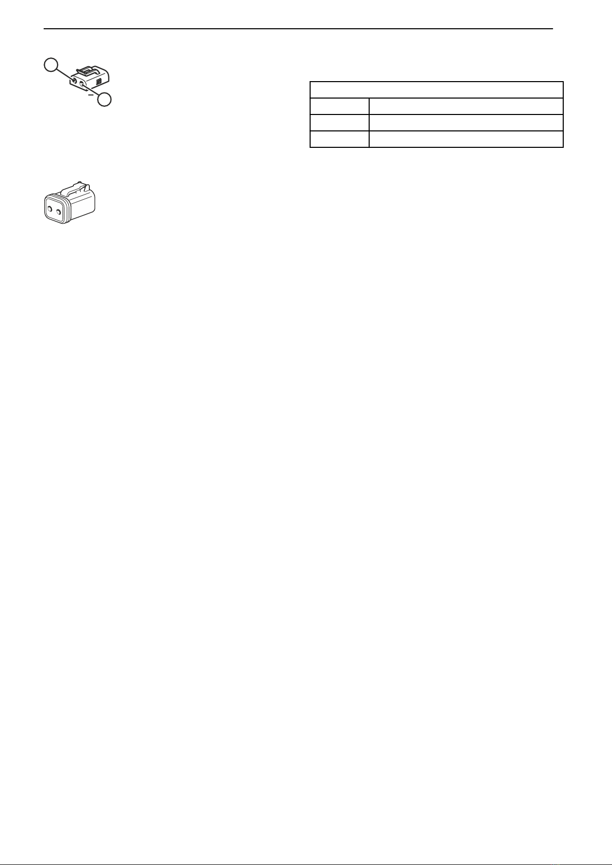
Connection for secondary battery
Engine 2-pin Deutsch connector
Pin Description
1 Battery + (fused 16A)
2 Battery –
External stop interface (Optional)
Engine 2-pin Deutsch connector
D9 and D16 engines: NO (normally open).
D13 can be ordered NO or NC (normally closed).
NO: External stop is triggered by the pins closure.
NC: External stop is triggered by opening of the circuit.
1
2
+
P0021264
Secondary battery interface female pin connector
P0021284
External stop interface female pin connector
Engine control interface, OEM interface
6 47706587 05-2015 © AB VOLVO PENTA

D9 engine connectors
1 Connector B
2 Connector A
3 External stop switch
4 Secondary battery
5 Diagnosis (VODIA connections)
3
4
5
2
1
P0021306
D9
Engine control interface, OEM interface
47706587 05-2015 © AB VOLVO PENTA 7

D13 engine connectors
1 Connector B
2 Connector A
3 External stop switch
4 Secondary battery
5 Diagnosis (VODIA connections)
3
4
5
2
1
P0021305
D13
Engine control interface, OEM interface
8 47706587 05-2015 © AB VOLVO PENTA

D16 engine connectors
1 Connector B
2 Connector A
3 External stop switch
4 Secondary battery
5 Diagnosis (VODIA connections)
3
5
2
1
4
P 2133000
D16
Engine control interface, OEM interface
47706587 05-2015 © AB VOLVO PENTA 9

CAN bus termination
Requirement for BB1
To avoid signal reflection interference on the CAN bus,
120Ω resistors must be provided at each end of the
network. Termination should be done at the nodes far-
thest away.
The EMS has built-in terminations.
AC
120Ω OEM
CAN
device
CAN
device
120Ω
EMS
B
P0021392
CAN bus termination
A EMS
B CAN device (No termination)
C OEM CAN device
Engine control interface, CAN bus termination
10 47706587 05-2015 © AB VOLVO PENTA

Source addresses
Applies to PEA2 electrical architecture
Refer to table below for used source addresses:
BB1
dec hex
EMS (Engine) 0 00 h
TECU (Transmission) 3 03 h
OEM controller 17 11 h
BBM 230 E6 h
Engine control interface, Source addresses
47706587 05-2015 © AB VOLVO PENTA 11

Power-up sequence
To power up the EMS, the ignition pin in the engine
connector must be connected to battery + (system
voltage). The EMS will then activate the Power Mod-
ule, acting as a main relay, and hold the power until
the power-down sequence is finished.
The engine management system will power up within
one second of ignition being switched on.
Bus interface
Associated input:
OEM interface connector pin 5 – ignition.
Engine control interface, Power-up sequence
12 47706587 05-2015 © AB VOLVO PENTA

Start
A start request is addressed by the 'Start request' sig-
nal on CAN. The engine will then start to crank and
continue to do so until one of the following conditions
become true:
•The engine speed exceeds a stated limit.
•The start signal goes inactive.
•A stop request is simultaneously active.
•The engine does not start.
•Starter motor overheat protection goes active.
•Low battery charge level.
Bus interface
Associated signals:
BB1: Rx: VP70 'Start request'
Tx: EEC1 'Engine starter mode'
Engine control interface, Start
47706587 05-2015 © AB VOLVO PENTA 13

Stop
There are two different ways to request engine stop:
1. Stop request on CAN
The 'Stop request' signal is sent on CAN in the VP70
message and results in instant engine stop.
This is the standard method to initiate engine stop.
2. External stop interface
For D9 and D16 engines, Normally Open are default:
External stop is triggered by the pins closure.
On D13 this can be set as Normally Open or Normally
Closed using the aftermarket tool (VODIA).
Bus interface
Associated signals:
BB1: Rx: VP70 'Stop request'
Engine control interface, Stop
14 47706587 05-2015 © AB VOLVO PENTA

Power-down sequence
In the standard configuration, where 'Ignition off stops
engine' is set to FALSE, the engine must be stopped
before Ignition off will start the power-down sequence.
If the 'Ignition off stops engine' option is selected, and
the ignition is turned off, the engine will be stopped and
then the system will initiate power down.
EMS power down
The EMS has a main relay self-hold function to ensure
that data is stored correctly in the memory before it
powers down.
The duration of the EMS power-down sequence is up
to 10 seconds. Do not switch off the battery until this
sequence is done.
Bus interface
Associated input:
OEM interface connector pin 5 – ignition.
Associated signals:
BB1: Rx: VP71 'Engine power down ack'
Engine control interface, Power-down sequence
47706587 05-2015 © AB VOLVO PENTA 15

Speed control
There are two ways of controlling the engine speed:
1 'Accelerator pedal position' in the CAN message
VP70.
2 Speed control mode in TSC1.
Source selector
On Variable speed engines, 'Idle speed select' can be
used as ‘limp home’ in the event of faulty pedal.
Pedal evaluation
Pedal evaluation is primarily through Volvo Proprietary
message VP70 received on the BB1 CAN link.
If no valid VP70 messages are received, engine speed
will be set to idle speed.
Pedal evaluation considers one signal in the VP70
message: 'Accelerator pedal position'
Variable speed
The 'Accelerator pedal position' signal is interpreted as
a 0-100% request where 0% means idle speed and
100% equals maximum engine speed. In the case of a
pedal signal fault the engine will go to idle speed.
When all pedal signal requirements are fulfilled again,
the pedal signal will be considered valid only after a
valid zero (0%) pedal demand.
The VP70 pedal request will also be overridden if an
external request is received in a TSC1 CAN message.
BB1::VP70
1
2
3
4
5
BB1::TSC1
::SA 0x03
::SA 0x11
Pedal
evaluation
TSC1
evaluation
speed
control
Source
selector
Target engine
speed/torque
Pedal target
engine speed
Target engine
speed/torque
4
P0021265
Schematic overview of speed control selection.
1 Pedal evaluation
2 TSC1 evaluation speed control
3 Pedal target engine speed
4 Target engine speed/torque
5 Source selector
Engine control interface, Speed control
16 47706587 05-2015 © AB VOLVO PENTA

Genset
On Genset applications there is a specific engine
speed controller in order to synchronize and perform
load sharing. A 50% 'Accelerator pedal counter'
demand corresponds to a rated nominal speed of 1500
or 1800 rpm.
When controlling the engine using the VP70 message,
it is possible to adjust the speed ±90 rpm by acceler-
ator position 0-100%.
Faulty accelerator pedal signals will result in a frozen
pedal demand value. Whatever value the accelerator
pedal position signal had prior to the pedal signals
becoming faulty, will be the pedal demand input to the
engine.
When all pedal signal requirements are fulfilled again,
a new pedal demand value can be considered by the
engine.
The VP70 pedal request will also be overridden if an
external request is received in a TSC1 CAN message.
Engine control interface, Speed control
47706587 05-2015 © AB VOLVO PENTA 17

Idle speed select
Variable speed
If the pedal signals become faulty, the engine will go
to idle. By releasing the pedal, the 'Idle speed select'
will go from zero to one.
When the 'Idle speed select' signal goes from one to
zero, the engine speed request will slowly ramp up to
70% of the maximum engine speed.
By releasing the pedal and setting the 'Idle speed
select' signal to one, idle speed is instantly requested.
Genset
If the pedal signals become faulty, the engine speed
request value will be frozen. If the 'Idle speed select'
signal goes from zero to one and engine load is low,
idle speed is requested.
Engine control interface, Speed control
18 47706587 05-2015 © AB VOLVO PENTA
This manual suits for next models
2
Table of contents
Other Volvo Engine manuals

Volvo
Volvo D4 User manual

Volvo
Volvo MD5A Instruction manual

Volvo
Volvo D1-13 B Instruction manual

Volvo
Volvo TAD1344GE Instruction manual

Volvo
Volvo D11F Guide

Volvo
Volvo D13H User manual

Volvo
Volvo D5 series User manual

Volvo
Volvo D16F Reference manual

Volvo
Volvo B6324S Operating and installation instructions

Volvo
Volvo D13J User manual