Volvo D13F User manual

R
OPERATOR'S MANUAL
ENGINE MAINTENANCE
PREVOST BUS
Volvo d13f engine

Foreword
This manual contains information concerning the operation and function
of the Volvo D13F engine. Please keep this manual in the vehicle at
all times.
Note: Illustrations in this manual are used for reference only and may
differ slightly from the actual vehicle. However, key components
addressed in this document are represented as accurately as possible.
Volvo Group North America, Inc.
Greensboro, NC USA
Order number: PV776-20158786
© 2008 Volvo Group North America, Inc., Greensboro, NC USA
All rights reserved. No part of this publication may be reproduced,
stored in retrieval system, or transmitted in any forms by any means,
electronic, mechanical, photocopying, recording or otherwise, without
the prior written permission of Volvo Group North America, Inc.

Contents
Volvo Engines .................................................................................... 1
Introduction ...................................................................................... 1
Fuel ................................................................................................. 1
Engine Oil ...................................................................................... 1
Engine Operation ........................................................................... 2
Engine Overview ............................................................................ 4
Engine Overview ............................................................................ 5
Exhaust Aftertreatment System ........................................................ 6
Safety Information ......................................................................... 6
Description ..................................................................................... 7
Exhaust Aftertreatment System Icons ............................................ 7
Operation ........................................................................................ 8
Regeneration ................................................................................ 8
Aftertreatment System Maintenance .............................................. 9
Engine Brake .................................................................................... 10
Engine Maintenance Intervals .......................................................... 11
Oil Change Intervals ...................................................................... 12
Cooling System ................................................................................ 12

Safety Information
IMPORTANT: Before driving this vehicle,
be certain that you have read and that
you fully understand each and every step
of the driving and handling information
in this manual. Be certain that you fully
understand and follow all safety warnings.
IT IS IMPORTANT THAT THE
FOLLOWING INFORMATION BE
READ, UNDERSTOOD AND ALWAYS
FOLLOWED.
The following types of advisories are used
throughout this manual:
DANGER
Danger indicates an unsafe practice that
could result in serious personal injury or
death. A danger advisory banner is in
white type on a black background with
ablack border.
WARNING
Warning indicates an unsafe practice that
could result in personal injury. A warning
advisory banner is in black type on a
gray background with a black border.
CAUTION
Caution indicates an unsafe practice that
could result in damage to the product. A
caution advisory is in black type on a
white background with a black border.
Note: Note indicates a procedure, practice,
or condition that must be followed in order
for the vehicle or component to function in
the manner intended.

Volvo Engines 1
Introduction
The Volvo D13F engine meets the emissions
standards which apply to all heavy-duty
diesel engines built after January 1, 2007 for
on-highway vehicles. The 2007 standards
reduce allowable emissions of nitrogen
oxides (NOx) by 50% and emissions of
particulates (soot) by 90% from previous
levels.
Key Features of the D13F Volvo Engine:
•Improved Fuel Economy
•Extended Oil Drain Intervals
•Improved Cooling Capacity
•Low Maintenance Diesel Particulate
Filter
•Enhanced Engine Brake Performance
Fuel
CAUTION
Diesel engines for 2007 and later model
year vehicles are designed to operate only
with Ultra Low Sulfur Diesel (ULSD)
fuel. Use of fuel other than ULSD will
reduce the efficiency and durability of
the engine, permanently damage the
advanced emission control systems,
reduce fuel economy and possibly
prevent the engine from running at all.
Manufacturer’s warranties are likely to
be rendered void by usage of improper
or incorrect fuel, and usage of fuels
other than ULSD fuel in diesel-powered
vehicles is illegal and punishable with
civil penalties. Use of fuel additives to
compensate for the lower sulfur content is
NOT recommended by Volvo.
Fuel sold for use in diesel-powered engines
for 2007 and later model year vehicles may
only contain a maximum sulfur content of
0.0015% by weight. This was done to reduce
particle emissions in the exhaust.
Engine Oil
VDS-4 or EO-O Premium Plus diesel engine
oil is mandatory for use in all 2007 emission
compliant Volvo engines. Chassis equipped
with a 2007 emission compliant engine,
which can be identified by the presence of a
Diesel Particulate Filter (DPF), also require
the use of Ultra Low Sulfur Diesel (ULSD)
fuel. EO-O Premium Plus oils exceed the
new API service category CJ-4.
2 Volvo Engines
Engine Operation
DANGER
Do not use ether or other combustible
starting aids in any Volvo engine.
Introduction of ether or similar starting
aids could cause a fire or explosion
resulting in severe property damage,
serious personal injury or death.
CAUTION
DO NOT crank the engine for more than
30 seconds at a time; wait two minutes
after each try to allow the starter to cool.
Failure to follow these instructions could
cause starter damage.
Note: Some starters are equipped with
starter protection. If the engine is running,
the starter temperature is too high or
the transmission is not in neutral, starter
engagement is inhibited.
Allow the engine to slow down and idle
for 3 to 5 minutes before shutting it off.
This allows the turbo to slow down and the
cooling system to dissipate the engine heat.
Switch the engine off by turning the ignition
key to the OFF position.
CAUTION
Shutting off an engine immediately after
high speed or full load operation can
damage the turbo and cause heat stress in
the engine. Always let the engine idle for
3 to 5 minutes before shutting it off.
Volvo Engines 3
Engine Shutdown System
DANGER
Failure to take the necessary precautions
when the STOP telltale is on can result in
automatic engine shutdown and the loss of
power steering. Vehicle crash can occur.
The engine shutdown system will
automatically derate or stop the engine when
one or more of the conditions listed below
reaches a critical stage:
•High Coolant Temperature
•Low Oil Pressure
•Low Coolant Level
•High Crankcase Pressure
•High Diesel Particulate Filter Soot
Level
When the shutdown is activated, the telltales
come on along with display symbols and the
buzzer is also activated. After a brief time,
the engine shuts down. Find a safe place to
pull off the road as soon as possible.
After the engine has been shut down by
the system, turn the ignition key to the off
position. If necessary, the engine can be
restarted for a brief time so that the vehicle
may be pulled off the road.
The alarm will remain activated until repairs
have been made to correct the problem that
caused the shutdown.
CAUTION
Continuously restarting the engine once
the shutdown system is active may result
in severe engine damage.
Refer to the Prevost manual for information
about the display symbols.
W3005171
4 Volvo Engines
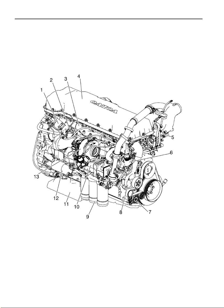
Engine Overview
W2006596
1 EGR Valve
2 Aftertreatment Fuel Injector
3 Exhaust Manifold
4 Valve Cover
5 Engine Preheater Element
6 Thermostat Cover
7 Belt Tensioner
8 Coolant Pump
9 Oil Filters
10 EGR Cooler
11 Oil Pan
12 Starter Motor
13 Turbocharger
Table of contents
Other Volvo Engine manuals


Volvo
Volvo XC90 - ANNEXE 951 User manual

Volvo
Volvo 2001 User manual

Volvo
Volvo TD420VE User manual

Volvo
Volvo B 17 User manual

Volvo
Volvo TAMD74C User manual

Volvo
Volvo EPA2007 D13F User manual

Volvo
Volvo TAD734GE User manual

Volvo
Volvo MB10A Instruction manual

Volvo
Volvo MD5A Instruction manual

Volvo
Volvo D20 User manual


