Group
21
Recondirioning
engine
Specificarions
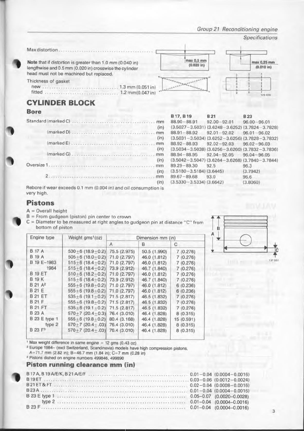
Max d
is
tortion
.....
I I
Na
te
thatll distortion is greater than 1.0 mm (0.040 in)
lengthwise and0.5 mm (0.020
in)
crosswisethecy1inder
head must not be machined but replaced.
mall 0
.5
mm
(0.
020
In) I
I
~
~'
-
10.010
ini
Th~~~~~~
~
.
f
.
~~~~~~
.............
.
..
1.3
mm
(0.051 in)
--
[>--~~::::~~T'
fitted 1.2
mm(0
.047 in)
~
~
CYLINDER
BLOCK
Bore
I • ,
i i
• ,
B17
,8
19
B21 8 23
.
i
,~~
Standard
(marked
el
..............................
mm 88.90-88.91 92.00-92.01 96.00-96.01
(i
n)
..
..........
mm
(in)
(3.5027-3.5031
~
(3.6248-3.6252~
(3.7824
-
3.7828~
(marked
D)
................
. 88.
91
-88.92 92.01- 92.02 96.
01
-96.02
(
3.5031
-3.5
034
~ (
3.6252
-
3.6256~
(3.7828-3.7832~
(marked
E)
...........
. . .
........
mm 88.92-88.93 92.02-92.03 96.02-96.03
(in)
.
mm
(in)
(
3.5034
-
3.5038~
(
3
.
6256
-
3
.
6260~
(3.7832-3.7836~
(marked
G)
. 88.94-88.95
92.04-92.05
96.04-96.05
(3.5
042
-
3
.S
047~
(3.6264-3.6268) (3.7840-3.7844)
Oversize 1
...
2.
..
.......
mm
(in)
.
..
mm
(in)
Rebore
ifwear
exceeds
0.1
mm
(0
.004 in)
and
oi!
c
onsumption
is
very high.
Pistons
A _ Overall height
B
'"
From
gudgeon
(
piston
) pin
center
to
crown
89
.29-
89.30 92.5 96.3
(3.5180- 3.S184) (3.6445) (3.7942)
89.67-89.68 93.0 96.6
(3.S33O- 3.5334) (3.6642)
(3
.8060)
e
'"
Diameter to
be
measured
at
right
angles
10
gudgeon
pin
at
dislan
ce "e" from
bottom
of
piston
Engine type Weight gms1(oz) Dimension mm
iN
A B C
817
A S30±6 (18.9±0.
2)
75.5 (2.975)
SO.5
(1.9901
7 (0.276)
819
A
5OS
±6 (18.0±0.2) 71
.0
(2.797) 46.0 (1.812) 7
(0
.276)
819
E- 1983 S15± 6 (18,4±0.2) 71.0 (2.797) 46.0 (1.812) 7 (0.276)
'984
S15t 6 (18,4±0.2) 73.9 (2.'91
2)
46.7 (1.640) 7 (0.276)
819
ET S10t 6 (18.2±0.2) 71.0 (2.797) 46.0 (1.812) 7 (0.276)
819
K S15±6 (18A±0.2) 73.9
(2.
'912)
46
.7 (1.840) 7 (0.276)
821
AZ
555±6 (19.8tO.2)
71
.0 (2.797) 46.0
(1
.812) 6 (0.236)
B
21
E 555±6 (l9.B ±0.2)
71
.0
(2
.797) 46.0 (1.812) 6 (0.236)
821
ET
535
±6 (19.1 t O.2) 71.5 (2.81
7)
46
.5 (1.832) 7 (0.276)
821
F
555
±6 (19.8tO.2) 71.5 (2.81
7)
46
.5 (1.832) 7 (0.276)
B
21
FT
535
±6 (19.1 t O.2) 71.5 (2.BI7)
46
.5 (1.832) 7 (0.276)
B23A
570
±7
(2O
.4±0.3 76.4 (3
.0
10)
46.4 (1.828) 8
(0
.315)
B23Elypel
555
±6 (19.8±0.2) 80.4
(3
.168) 46.4
(1
.828) 15
(0
.591)
typa 2
570
±7
(2O.4
±.
03 76.4
(3
.0
10)
46
.4 (1.828) 8 (0.315)
B23P
570
± 7 (20.4±.03 76.4 (3.010) 46,4
(1
.828) 8 (0.315)
I
Max
weight
ditlerence
'"
same
engine _
12
gms (OA3
Oz)
2Europe 1964-
(exel
Switzerland,
Scandinavl8)
medels have high compresslorl pistons,
A-
71.7
rTYTl
(2.82 in); 8_48
.7
mm
(1.84 in): C",7
mm
(0
.
28
in)
lplstons
dished
on
engine numbars 499846,
499890
Piston
running
clearance
mm
l[
in)
817A,B19A1E/K,B21A1E/F
............................
.
...............
0.01 -0.04
(0.0004-0.00
1
6)
819
ET
...................
0.03-0.06 (0.0012-0.0024)
821
ET&
FT
...........
..........
..
0.02-0.04 (0.0008-0.0016)
823A
..
................
.................
...
0.
01
- 0.04 (0.0004-0.001
6)
B 23 E type 1
......
. . . . . .
..
0.
OS
- 0.07 (0.0020-0.0028)
type 2
......
. . . . . . . . . . . . . . . . . . .
.. ..
0.Q1
-0.04 (0.0004-0.0016)
B 23 F
.........................................................
0.
01-0
.04 (0.0004-0.0016)
UJ
551
3