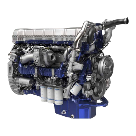
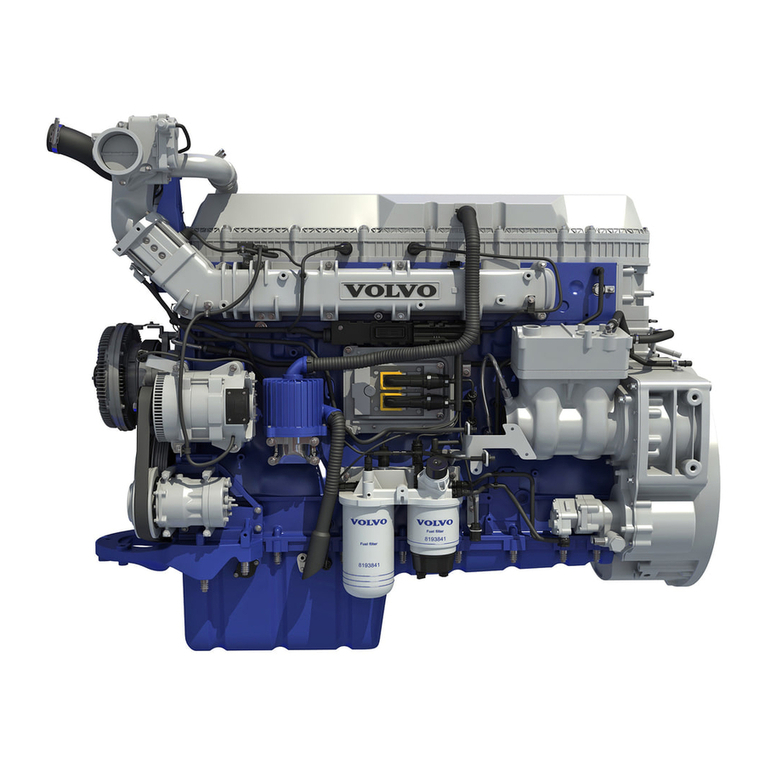
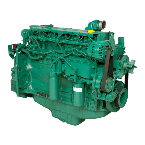
Volvo TAD1240GE User manual

Generating set and industrial engines
12 litre (EDC III)
OPERATORSMANUALp
Doosan purchased Bobcat Company from Ingersoll-Rand Company in
2007. Any reference to Ingersoll-Rand Company or use of trademarks,
service marks, logos, or other proprietary identifying marks belonging
to Ingersoll-Rand Company in this manual is historical or nominative
in nature, and is not meant to suggest a current affiliation between
Ingersoll-Rand Company and Doosan Company or the products of
either.
Revised (10-12)

Enginedata
Engine designation ........................... Product number ....................................
Serial number .........................................................................................................
Clutch, type/nr. .......................................................................................................
NearestVolvoPentaservicelocation
Name .......................................................................... Telephone....................
Address...................................................................................................................
© 2001 AB VOLVO PENTA
Volvo reserves the right to make changes
Printed on environmentally friendly paper
Foreword
Volvo Penta industrial engines are relied upon throughout the world,
in both mobile and stationary applications, under some of the most
rigorous conditions imaginable. This is not by chance.
After more than 90 years of producing engines the name Volvo Penta
has come to symbolize reliability, technical ingenuity, first-class perfor-
mance and longevity. We believe that these characteristics are also
ultimately your requirements and expectations for new Volvo Penta
industrial engines.
To make certain that your expectations are matched, we ask that
you read carefully through the instruction book before starting
the engine.
Sincerely
AB VOLVO PENTA

1
Safetyinformation.................................................. 2
Safety instructions for operation and
maintenance ......................................................... 3
Introduction............................................................ 6
Environmentalresponsibility ................................. 6
Running-in............................................................. 6
Fuel and oils ......................................................... 6
Maintenanceandreserveparts ............................. 6
Certifiedengines ................................................... 7
Presentation ........................................................... 8
Technicaldescription ............................................ 8
Identificationnumbers........................................... 9
EDC III................................................................ 10
Orientation .......................................................... 11
Instrument ............................................................ 12
Instrumentbox ..................................................... 12
Startingtheengine............................................... 13
Beforestarting .................................................... 13
StartingprocedureEDCIII ................................... 13
Instrumentbox.................................................... 14
Volvo Penta start lock......................................... 14
Start-upunderextremecold ................................ 15
Never use starting fluid ....................................... 16
Start-upwithhelperbatteries............................... 16
Operation .............................................................. 17
Checkingtheinstruments ................................... 17
Alarmsandtroubleindicators .............................. 17
RPMregulation ................................................... 18
Clutch ................................................................. 18
Low-loadoperation .............................................. 18
Shutting down the engine ................................... 19
Prior to shut-down .............................................. 19
Shut-down........................................................... 19
Aftershut-down................................................... 19
Extrashut-down .................................................. 19
Contents
Maintenanceschedule ......................................... 20
Maintenanceschedule ........................................... 20
Newlyrebuiltengine ............................................ 21
Maintenance ......................................................... 22
Engine,general ................................................... 22
Lubricationsystem.............................................. 26
Lubricationoil...................................................... 27
Coolingsystem ................................................... 30
Coolant,general .................................................. 30
Fuel system........................................................ 35
Electric system................................................... 39
Clutch ................................................................. 43
Preparationforstorage ........................................ 44
Preparationforstorage....................................... 44
Preparationafterstorage..................................... 45
Troubleshooting................................................... 46
Symptoms and possible causes ......................... 46
Diagnosticfunction.............................................. 47
Diagnosticfunction ............................................. 47
Regardingthediagnosticbutton’sindication
blinker ................................................................. 47
Readoutoferrorcodes........................................ 47
Erasingerrorcodes............................................. 48
Diagnostictroublecodes..................................... 49
Technicaldata ...................................................... 55
General ............................................................... 55
Lubricationsystem.............................................. 55
Fuel system........................................................ 56
Coolingsystem ................................................... 56
Electric system................................................... 57
CALIFORNIA
Proposition 65 Warning
Dieselengineexhaust and some of itsconstituentsare known to
theStateof California to cause cancer, birth defects,andother
reproductiveharm.

2
Safety information
Read this chapter very carefully. It concerns your safety .How safety information is presented in the instruction
book and on the product is described here. You will also find an overall picture of the basic safety procedures for
operation of the engine.
Make sure that you have the correct instruction book before reading any further. If you do not, please con-
tact your Volvo Penta dealer.
Incorrect operation can lead to injuries and/or product or property damage. It is therefore impor-
tant to read through the instruction book very carefully before you start the engine or perform
maintenance or service work. If there is anything that you are unclear on or unsure about even af-
ter reading the book, please contact your Volvo Penta dealer for assistance.
This symbol is used in the instruction book and on the product to let you know that it con-
cerns safety information. Always read this information very carefully.
In the instruction book warning texts are handled according to the following priority system:
WARNING! Warns of risk of injury, extensive damage to the product or other property, or
that serious functional problems can occur if the instruction is not followed.
IMPORTANT! Used to call attention to things that can cause damage or functional
problemstothe productorproperty.
NOTE!Used to call attention to important information that can make the work process or opera-
tion go more smoothly.
This symbol is used in certain cases on our products and refers to important information in
the instruction book. Make sure that warning and information symbols on the engine and trans-
mission are always visible and legible. Replace symbols that have been damaged or painted
over.

Safety information
3
Starting lock
If the instrument panel does not have a key switch
the engine compartment should be lockable to pre-
vent unauthorized personnel from starting the engine.
A lockable main switch may be used as an alterna-
tive.
Maintenance and service
tasks
Knowledge
In the instruction book you will find instructions for
how the most common maintenance and service
tasks can be carried out in a safe and correct man-
ner. Read the instructions carefully before initiating
work.
Literature covering more extensive work is available
from your Volvo Penta dealer.
Never attempt a procedure if you are not completely
certain regarding how it should be performed. Contact
your Volvo Penta dealer for assistance.
Shut down the engine
Shut down the engine before opening or removing the
engine access panel/hood. Maintenance and service
procedures should be carried out on a stopped engi-
ne unless otherwise specified.
Prevent an undesired start-up by removing the star-
ting key and disconnecting the electricity with the
main switch and locking it in the disconnected posi-
tion. A warning notice should also be placed at the
operating station advising that work is being carried
out.
Working with or getting close to a running engine is a
safety risk. Hair, fingers, loose-fitting clothing or a
dropped tool can get caught in rotating parts causing
severe injury. Volvo Penta recommends that all ser-
vice work that requires that the engine be running be
assigned to an authorized Volvo Penta repair facility.
Safety instructions for operation and maintenance
Daily checks
Make a habit of always visually checking the engine
and engine compartment prior to operation (before
starting the engine) and after operation (after shut-
ting down the engine). This will help you to quickly
notice if fuel, coolant or oil leaks or any other abnor-
mal conditions have occurred or are occurring.
Fuel filling
There is a risk of fire and explosion when filling tanks
with fuel. Smoking is forbidden and the engine must
be stopped.
Never overfill the tank. Make sure that the cap is cor-
rectly closed.
Use only the fuel recommended in the instruction
book. Fuel of the wrong grade can cause the engine to
run incorrectly or not at all. On a diesel engine it can
also lead to seizure of the injection system and over-
revving the engine, putting both the machine and near-
by people at risk.
Carbon monoxide poisoning
Only start the engine in a well-ventilated space.
During operation in an enclosed space both exhaust
and crankcase gases must be properly vented.
Operation
The engine should not be operated in environments
with surrounding explosive substances due to the fact
that the electrical and mechanical components can
cause sparks.
Getting close to a running engine is a safety risk.
Hair, fingers, loose-fitting clothing or a dropped tool
can get caught in rotating parts causing severe injury.
If the engine has been delivered without protective co-
verings, all rotating parts and hot surfaces should be
covered as necessary following installation to insure
personal safety.

Safety information
4
Safety instructions for operation and maintenance (cont.)
Lifting the engine
When lifting the engine use the lifting eyes that are
mounted on the engine. Always make sure that the
lifting device is in good condition and has sufficient
capacity for the lift (the weight of the engine as well
as all necessary extra equipment). For safe handling
the engine should be lifted with an adjustable lifting
boom. All chains or cables should run parallel to each
other and as possible at right angles to the upper sur-
face of the engine. Note that extra equipment that is
mounted on the engine can change its center of grav-
ity. Special lifting equipment may be necessary to in-
sure correct balance and safe handling. Never perform
work on a motor that is only hanging in a lifting devi-
ce.
Before starting
Replace all protective covers that have been removed
prior to starting the engine. Make sure that no tools or
other objects have been left near the engine.
An engine with a turbocharger may never be started
without the air filter being mounted. The rotating com-
pressor wheel in the turbo can cause severe injuries.
There is also a risk that foreign objects can be sucked
in causing damage to the machine.
Fire and explosion
Fuel and lubricating oil
All fuels, most lubricating substances and many che-
micals are flammable. Always read and follow all ins-
tructions listed on the packaging.
Work on the fuel system must be performed on a cold
engine. Fuel leakage and spillage onto hot surfaces or
electrical components can cause a fire.
Store oil and fuel-soaked rags and other flammable
material in a fire-safe manner. Oil-soaked rags can
spontaneously ignite under certain conditions.
Never smoke while filling with fuel or lubricating oil, in
proximity to the filling station or in the engine compart-
ment.
Non-original parts
Components of the fuel and electrical systems on Vol-
vo Penta engines are designed and manufactured to
minimize the risk of explosion or fire according to app-
licable requirements.
Use of non-original parts can result in explosion or
fire.
Batteries
Batteries contain and develop oxyhydrogen gas, espe-
cially while charging. Oxyhydrogen gas is easily flam-
mable and very explosive.
Smoking, open fire or sparks must never be allowed
near batteries or the battery compartment.
An improper connection of a battery cable or booster
cable can cause a spark that can in turn cause the
battery to explode.
Starting fluid
Never use starting spray or other similar substances
to help start an engine with air pre-heating (glow plugs/
starting coil). This could cause an explosion in the in-
take tract. This poses a risk of injury.
Hot surfaces and fluids
A warm engine always creates a risk for burns. Be ca-
reful of hot surfaces. For example: exhaust pipes, tur-
bo, oil sump, turbo pressure pipe, heating coil, hot
coolant and warm lubricating oil in lines and hoses.
Chemicals
Most chemicals, for example glycol, rust prevention
substances, preserving oils, degreasers, etc. are ha-
zardous to your health. Always read and follow the di-
rections on the packaging.
Certain chemicals, for example preserving oils are
flammable and also hazardous if inhaled. Make sure
that you have good ventilation and use a protective
mask when spraying. Always read and follow the di-
rections on the packaging.
Keep chemicals and other hazardous materials out of
reach of children. Bring leftover or used chemicals to
an environmental station for destruction.
Lubrication system
Warm oil can cause burns. Avoid skin contact with
warm oil. Make sure that the lubrication system is not
pressurized prior to performing service. Never start or
operate the engine without the oil filler cap in place
due to risk of oil being thrown out.
Safety information
5
Cooling system
Avoid opening the coolant filler cap when the engine is
warm. Steam or hot coolant can squirt out causing
burns.
If the filler cap, coolant lines, taps or so on must be
opened or removed while the motor is warm the filler
cap must be opened slowly and carefully so that pres-
sure is released before the cap is completely removed
and work is started. Note that the coolant can still be
hot and cause burns.
Fuel system
Always protect your hands when searching for leaks.
Streaming pressurized liquids can make their way into
body tissues causing serious injuries. There is a risk
of blood poisoning.
Always cover the generator if it is placed under the
fuel filter. A fuel spill can damage the generator.
Electrical system
Disconnect the power
Before servicing the electrical system the engine
should be stopped and the electrical power switched
off using the main switch/breakers. External power to
the engine heater, battery charger or other equipment
mounted on the engine must be switched off.
Batteries
Batteries contain a very strong corrosive electrolyte.
Protect your eyes, skin and clothing during charging
or other handling of batteries. Always use safety glas-
ses and gloves.
In case of skin contact, wash with soap and large
quantities of water. In case of eye contact rinse im-
mediately with large quantities of water and contact a
doctor as soon as possible.
Electric welding
Remove the positive and negative cables from the
batteries. Next, remove all connections to the genera-
tor.
Always connect the welding clamp to the component
to be welded and as close to the place to be welded
as possible. The clamp must never be attached to the
engine or so that the current can pass through any be-
arings.
When finished welding: Always connect all connec-
tions to the generator before the battery cables are re-
connected.

6
Introduction
This instruction book has been compiled to give you the best possible use of your Volvo Penta industrial engine.
It contains the information you need to operate and take care of the engine in a safe and correct manner. We the-
refore ask you to read the instruction book carefully and to learn to handle the engine, controls and additional
equipment in a safe manner before you start the engine.
IMPORTANT! The instruction book describes the engine and equipment that are sold by Volvo Penta. In
certain applications there can be variations of for example controls and instrumentation that concern both
appearance and function. In these cases we refer you to the instruction book for the application in question.
Environmental care
We all want to live in a pure and healthy environment
where we can breathe fresh air, see healthy trees,
have clean water in our lakes and oceans and where
we can enjoy the sunshine without fearing for our
health. Unfortunately this is not always the case today
but it is a situation that we all must work to preserve
and protect.
As an engine manufacturer Volvo Penta has a special
responsibility, therefore care for the environment is a
core value in our product development. Today Volvo
Penta has a broad engine line where large steps have
been taken towards reducing exhaust emissions and
improving fuel economy, engine noise and so on.
We hope that you will be careful to preserve these
qualities. Always follow the advice in the instruction
book regarding fuel quality, operation and maintenan-
ce so that you can avoid unnecessary damage to the
environment. Contact your Volvo Penta dealer if you
notice changes such as decreased fuel economy or
increased exhaust smoke.
Remember to always bring hazardous waste such as
drained oil, coolant, used batteries etc. to an environ-
mental station for destruction.
Through our mutual efforts we can make a valuable
contribution to the environment.
Running-in
The engine should be ”run-in” during the first
10 hours of operation according to the following:
Run the engine as with normal operation. Full-throttle
operation should not occur for more than short peri-
ods. Do not run the engine for long periods of time at
steady RPM during the run-in period.
An increase in the consumption of lubricating oil is
normal during the first 100–200 hours of operation. It
is therefore important to check the oil level more often
that is normally recommended.
When a clutch is mounted it should be inspected more
frequently during the first days of operation. Adjust-
ment may be required to compensate for initial wear of
the plates.
Fuel and oils
Only use fuel and oils of a grade matching that recom-
mended in the instruction book (see the chapter on
”Maintenance” under the fuel and lubricating system
headings). Other grades can cause problems with
operation, decreased fuel economy and in the long run
even a shortened lifetime of the engine.
Always change the oil, oil and fuel filters according to
the prescribed intervals.
Maintenance and replacement
parts
Volvo Penta engines are constructed for maximal de-
pendability and longevity. They are built to survive in
demanding environments but also to have the mini-
mum possible impact on the environment within which
they operate. Regular maintenance and use of Volvo
Penta original parts will preserve these properties.
Volvo Penta has a worldwide network of authorized
dealers. They are specialists on Volvo Penta products
and have accessories, original parts, test equipment
and the special tools that are necessary for high-quali-
ty service and repair work.
Always adhere to the maintenance schedules lis-
ted in the instruction book and remember to prov-
ide the engine/transmission identification number
when ordering service and parts.

Introduction
7
Certified engines
For those of you who own an emissions-certified
engine that is used in an area where exhaust emis-
sions are legally regulated, it is important to re-
cognize the following:
A certification signifies that an engine type has been
inspected and approved by the authorities in question.
The manufacturer of the engine guarantees that all
engines of the same type will match the engine that
was certified.
This places the following special requirements
upon the maintenance and service that you per-
form on your engine:
•Maintenance and service intervals recommended
by Volvo Penta must be followed.
•Only Volvo Penta original parts may be used.
•Service on the injector pumps, pump settings and
injectors must always be performed by an
authorized Volvo Penta repair facility.
•The engine may not be rebuilt or modified with the
exception of accessories and service kits
developed by Volvo Penta for the engine.
•No changes may be made to the engine’s exhaust
or intake air systems.
•No seals may be broken by non-authorized
personnel.
In all other cases follow the advice in the instruction
book regarding operation, maintenance and service.
IMPORTANT! In cases of neglected or deficient
maintenance/serviceas wellas useof non-origi-
nal parts AB Volvo Penta will no longer be able
to assure that the engine meets conditions of
certification.
Volvo Penta will not settle damages and/or costs
associated with such instances.
Warranty
Your new Volvo Penta industrial engine is covered by a limited warranty according to the conditions
and instructions that are contained in the Warranty and Service book.
Note that AB Volvo Penta’s responsibility is limited to that which is named in the Warranty and Service
book. Read it carefully immediately following delivery. It contains vital information on subjects such as
the warranty card,
services, and maintenance that is your responsibility as the owner to be aware of, check on and per-
form. AB Volvo Penta may otherwise completely or partially deny warranty claims.
Contact your Volvo Penta dealer if you do not have a Warranty and Service book as well as a
customer copy of the warranty card.

8
Presentation
TAD TWD
TAD1240GE, TAD1241GE/VE, TAD1242GE/VE and TWD1240VE are inline, direct-injected, 6-cylinder industrial
diesel engines.
They are equipped with electronically controlled fuel management, turbochargers, intercoolers and thermostati-
cally regulated cooling systems and electronic RPM regulation.
Technical description
Engine and cylinder block
– Cylinder block and cylinder head of alloyed cast
iron
– Seven main bearing induction hardened
crankshaft
– Wet replaceable cylinder liners
– Cast aluminum pistons with oil cooling
– Three piston rings, the top of which is of the
”keystone” variety
– Induction hardened overhead camshaft with roller
rocker arms
– Four valves per cylinder
– Replaceable valve seats and valve guides
Fuel system
– Microprocessor-based control unit for fuel delivery
(EDCIII)*
– Gear-driven feeder pump
* EDC III (”Electronic Diesel Control”), see separate description.
– Centrally placed unit injector with
electromagnetically controlled fuel valves
– Fuel filter of spin-on type and a water separating
filter
Lubrication system
– Water-cooled oil cooler
– Gear-driven oil pump
– Full flow and bypass oil filters of spin-on type
Intake air compression system
– Turbocharger
Cooling system
– Cooler with expansion tank
– Water-cooled line-type intercooler (TWD)
Air-cooled intercooler (TAD)
Electrical system
– 24V electric system with generator (60A) with
charging sensor

Presentation
9
The above plate shows:
(K) Engine family
(J) Swept volume
(A) Engine designation
(F1)Valve clearance, inlet
(F2)Valve clearance, outlet
(I) Emission Control devices
(P) Only constant RPM
(E) Part number – decal
(B) Engine code (in engine family)
(C) Output/RPM
(D) Fuel quantity
(M) Engine speed
(H) Certification approval number (EU)
Explanation of engine designation:
Ex. TAD1240GE/TWD1240VE
T – Turbo
A – Air-to-air Charge air cooler
W – Water to air, intercooler
D – Diesel engine
12 – Swept volume, liter
4 – Generation
0 – Version
G – Gen Set engine
V – Stationary and mobile operation
E – Emissions check
Location of engine plates
The plate below shows:
1 Engine designation
2 Serial number
3 Specification number
Identification numbers
The plate below shows:
1 Engine designation
2 Specification number
3 Serial number (last six digits) engine block
The plate below shows:
A Engine designation
B Net engine output (without fan)
C Max. rpm
D Computer kit number
E Product number

10
Presentation
Control unit (1)
The EDC III system’s processor is located in the con-
trol unit, protected from moisture and vibrations.
The processor continually receives information regar-
ding:
– rpm levels
– intake boost pressure
– intake temperature
– coolant temperature
– oil pressure
– oil temperature
– fuel alarm, includes both ”water in fuel” as well as
”fuel pressure”
– coolant level
The information provides a precise overview of current
operational conditions making it possible for the pro-
cessor to do such things as determine the correct fuel
dosage and check on the engine’s condition.
Fuel management
The fuel needs of the engine are analyzed up to 100
times per second. Fuel injection quantity and timing
are controlled electronically via fuel valves in the unit
injectors.
This means that the engine always receives the cor-
rect amount of fuel under all operating conditions,
providing benefits including improved fuel economy
and minimized exhaust emissions.
Diagnostic function
The diagnostic system’s function is to detect and lo-
calize disturbances within the EDC III system, to pro-
tect the engine as well as to insure the ability to con-
trol the engine during serious disturbances.
If a disturbance is detected a diagnostic indicator in
the control panel will begin to blink. Pushing the dia-
gnosis button will provide the operator with an error
code to assist in locating the problem.
EDC III
EDC III stands for ”Electronic Diesel Control” and is an electronic system with CAN (Controller Area Network)
communication for diesel engine management. The system was developed by Volvo Penta and includes such pa-
rameters as fuel management and diagnostic functions.
1

11
Presentation
1. Expansion tank
2. AC generator
3. Control unit
4. Air filter
5. Starter motor
6. Fuel pre-filter with water sensor
7. Fuel filter with fuel pressure sensor
8. Oil dipstick
9. Oil filler
10. Intercooler (TAD only)
Orientation
The picture shows TAD1240GE, TAD1241GE and TAD1242GE
variants.

12
Instrument
1. Engine oil pressure.
2. Diagnosis lamps. The error codes are read from
the diagnosis lamp.
3. Coolant temperature.
4. Indicator lamps Pre-heating and after-heating.
5. Tachometer (rpm).
6. Throttle.
7. Start button.
8. ON button. Used to start the system. Sends
current to the system only when it is pushed. It
must therefore be held down until the main relay
is activated. This takes about one second.
9. Pre-heat button. Used to pre-heat the engine prior
to start. Pre-heating is automatically adjusted by
the system. The system also has after-heating.
10. Diagnosis button. Used to read out error codes.
See ”Reading out error codes”.
11. Stop/Off button.
12. Warning lights (x6) from the left: oil pressure, oil
temperature, battery charging, coolant tempera-
ture, coolant level, fuel alarm (includes both ”water
in fuel” as well as ”fuel pressure”).
Instrumentbox

13
Starting the engine
Make a habit of always visually checking the engine and engine compartment prior to starting the engine. This will
help you to quickly notice if any abnormal conditions have occurred or are occurring. Check also to verify that the
instruments show normal values after start-up.
Before starting
•Check that the oil level is between the MIN and
MAX marks. See the chapter ”Maintenance,
lubrication system”.
•Open the fuelcocks.
•Make sure that there is no leakage of coolant, fuel
or oil.
•Check the air filter’s pressure drop indicator. See
the chapter ”Maintenance, Engine, general”.
•Check the coolant levels and that the radiator is
not blocked on the outside. See the chapter
”Maintenance, cooling system”.
WARNING! Donotopen thecoolantfillercap (1)
when the engine is warm. Steam or hot coolant
can squirt out
NOTE! Donot openthe pressure cap(2).
•Turn on the main switches.
IMPORTANT! Neverswitch off thepower with
the main switch while the engine is running. The
generatorcanbedamaged.
•Set the throttle to idle and disengage the clutch/
put the transmission in neutral.
Start-up procedure EDC III
The throttle must always be in the idle position during
start. The EDCIII system makes sure that the engine
always receives the correct amount of fuel - even
during cold starts!
Pre-heating time is set according to engine temperatu-
re and can be active for up to 50 seconds both before
and after start-up.
The starter motor’s activation time is limited to
20 seconds, after which the starter circuit is broken
for 80 seconds to prevent the starter motor from over-
heating.

Starting the engine
14
Instrument box:
With pre-heating
1. Push in ”ON” (1).
2. Push the ”Pre-heat” button (2) and wait until the
”Pre-heat indicator” (4) goes out.
3. Push the ”Start” button (3).
Without pre-heating
1. Push in ”ON” (1).
2. Push the ”Start” button (3).
3. Let the engine run at 500–700 rpm for the first 10
seconds.
Following this, warm up the engine using low rpm
and low loading.
IMPORTANT!Neverrev-uptheenginewhen it is
cold.
Volvo Penta start lock:
1. Turn the key to the ”I” position and check the
indicator lamps.
2. Position”II”. Pre-heating is activated (pre-heating
is an option). Wait until the pre-heating indicator
lamp goes out. Pre-heating time is dependent
upon engine temperature.
3. Start the engine with position “III”. Let the key re-
turn to position ”I” immediately once the engine
has started.
NOTE! The engine has a built-in starter motor inter-
lock to prevent inadvertent activation of the starter
motor while the engine is running. The key must be
turned to the “O” position before attempting to start
again.
Let the engine run at 500–700 rpm for the first 10 se-
conds. Following this, warm up the engine using low
rpm and low loading.
IMPORTANT!Neverrev-uptheenginewhen it is
cold.
Alternative pre-heating:
1. Turn the key to the ”I” position and check the
indicator lamps. Pre-heating activates
automatically (pre-heating is an option). Pre-
heating time is dependent upon engine tempera-
ture.
2. Start the engine with position ”III”. Let the key re-
turn to position ”I” immediately once the engine
has started.

Starting the engine
15
Start-up under extreme cold
To facilitate and in certain cases allow start-up under
extremely cold conditions certain procedures must be
followed:
Use a winter fuel (from a well-known supplier) that has
been approved for the temperature in question. This
minimizes the risk of wax precipitation in the fuel sys-
tem. During extremely low temperatures use of a fuel
heater is recommended.
In order to insure sufficient lubrication we recommend
use of synthetic oil of the recommended viscosity for
the temperature in question (see chapter ”Maintenan-
ce, lubrication system). Synthetic oils retain their lub-
ricating properties over a wider range of temperatures
than mineral oils.
Pre-heat the coolant by using a separately mounted
electric engine heater. In extreme cases it can be ne-
cessary to use a diesel-powered engine heater. Con-
sult your Volvo Penta dealer.
IMPORTANT! Make sure that the cooling sys-
tem is filled with a glycol mixture. See the
chapter”Maintenance,coolingsystem”.
The batteries must be in good condition. Cold reduces
the capacity of the batteries. Increasing the total bat-
tery capacity may be necessary.

Starting the engine
16
Start with booster batteries
WARNING!Batteries(especiallybooster
batteries) contain oxyhydrogen gas that is very
explosive. A spark, which can occur if the
boosterbatteriesareimproperlyconnected,can
be sufficient to cause a battery to explode
causingdamageand/orinjury.
1. Make sure that the booster batteries are
connected (in series or in parallel) so that the gro-
und voltage corresponds to the engine’s system
voltage.
2. First connect the red booster cable (+) to the
booster battery and then to the dead battery. Then
connect the black booster cable (-) to the booster
battery, then to a place that is a distance away
from the dead battery, i.e. next to the main
switch on the negative wiring or at the negative
cable’s connection to the starter motor.
3. Start the engine.
WARNING!Donotdisturbtheconnectionswhile
attempting to start the engine (risk for creating
sparks) and do not lean over any of the batteries.
4. Remove the cables in reverse order.
WARNING!Thenormalcablestothestandard
batteries must absolutely not be modified.
Never use starting spray
WARNING!Neverusestartingsprayorother
similar substances to help start an engine. This
could cause an explosion in the intake tract. This
poses a risk of injury.

17
Operation
Proper operating technique is important both to fuel economy and the engine’s useful life. Always allow the engine
to reach normal operating temperature before applying maximum power. Avoid sudden throttle changes and high
RPM operation.
Check the instruments
Check the instruments directly after start-up and at re-
gular intervals during operation. The indicators should
be within the green areas.
Coolant temperature: Green zone (75°C-95°C).
Oil pressure, warm motor: Green zone. At idle it is
normal to have a lower value.
IMPORTANT!Forenginesundercontinuousope-
ration lubricating oil levels must be checked at
least every 8 hours. See the chapter
”Maintenance,lubricationsystem”.
Alarms and error indications
If the EDCIII system receives abnormal signals from
the engine the ”Diagnostic lamp” (1) will begin to blink.
Pushing the ”Diagnostic button” (2) will give a error
code that can assist in locating the problem. Additio-
nal information on error codes and location of pro-
blems is in the chapter ”Problem location”.
The following conditions apply when the Volvo
Penta instrument box is used:
•In case of excessively low oil pressure or
excessively high coolant temperature the engine
is shut down automatically and the acoustic alarm
is activated.
•In case of excessive charge-air temperature and
oil temperature the EDCIII system temporarily
reduces the engine power until the value in
question normalizes. A warning lamp is activated.
•In case of low coolant level, if the engine is
equipped with a coolant level sensor the engine is
shut down and the acoustic alarm is activated.
The warning lamp is activated.
•In case of lack of electrical charging a warning
lamp is activated.
•In case of a fuel warning a warning lamp is
activated.
For other applications we refer to the application
instruction book in question.

Operation
18
Low-load operation
Avoid prolonged operation at idle or at low loading.
This can cause increased oil consumption and even-
tual oil leakage from the exhaust pipe due to oil lea-
king past the turbocharger seals and following with the
charge air into the intake tract during low turbo pressu-
re conditions.
A consequence of this is a build-up of carbon deposits
on the valves, tops of the pistons, in the exhaust
ports and the exhaust turbo.
Low loads also result in a combustion temperature
that is so low that complete combustion of the fuel
can not be guaranteed. Possible consequences of this
include fuel dilution of the lubrication oil as well as lea-
kage from the exhaust pipe.
If the following items are performed as a comple-
ment to the normal care of the engine there will be
no risk of operational disturbances due to opera-
tion at low loads:
•Keep low load operations to a minimum. If
periodic test operation of the engine is done
without load every week, the operating time
should be limited to approximately 5 minutes.
•Operate the engine under full load for
approximately 4 hours once a year. Carbon
deposits in the engine and exhaust system will
thereby have the chance to burn off.
Throttle
The throttle (A) is mounted on the right side of the in-
strument box. Avoid sudden and extreme changes in
throttle position.
Clutch
A clutch is optional. Engage the clutch at a
1000–1200 rpm max.
N= Neutral
E= Engaged
This manual suits for next models
5
Table of contents
Other Volvo Engine manuals

Volvo
Volvo D9 series User manual

Volvo
Volvo EPA2007 D13F User manual

Volvo
Volvo D20 User manual

Volvo
Volvo TAMD74C User manual

Volvo
Volvo 2001 User manual

Volvo
Volvo B6324S Operating and installation instructions

Volvo
Volvo D20 User manual

Volvo
Volvo B 17 User manual

Volvo
Volvo 819 E User manual

Volvo
Volvo B16B Setup guide
Popular Engine manuals by other brands

Tahmazo
Tahmazo ER-2208K instruction manual

Robin America
Robin America EK13 Service manual

Perkins
Perkins 1104D Operation and maintenance manual

Briggs & Stratton
Briggs & Stratton 21000 Series Operating & maintenance instructions

SOMFY
SOMFY Sonesse 30 RS485 installation instructions

Kohler
Kohler Command PRO ECV630 Service manual