Vox Power NEVO+600 Series User manual

NEVO+600 Series
INSTALLATION MANUAL
_____________________________________________________________________________________________________
Page 1of 4Vox Power Limited | Unit 2, Red Cow Interchange Estate, Ballymount, Dublin 22, D22 Y8H2, Ireland | T +353 1 4591161 | www.vox-power.com
PLEASE READ THIS INSTALLATION MANUAL CAREFULLY BEFORE INSTALLING THIS PRODUCT AND KEEP THIS MANUAL FOR FUTURE REFERENCE.
All specifications are believed to be correct at time of publishing. Vox Power Ltd reserves the right to make changes to any of its products and to change or improve any part of the specification,
electrical or mechanical design or manufacturing process without notice. Vox Power Ltd does not assume any liability arising out of the use or application of any of its products and of any information
to the maximum extent permitted by law. No license, express or implied, by estoppel or otherwise, to any intellectual property rights is granted by this document or by any products of Vox Power Ltd.
VOX POWER LTD DISCLAIMS ALL WARRANTIES AND REPRESENTATIONS OF ANY KIND WHETHER EXPRESS OR IMPLIED, INCLUDING, BUT NOT LIMITED TO, IMPLIED WARRANTIES OF SUITABILITY, FITNESS
FOR PURPOSE, MERCHANTABILITY AND NONINFRINGEMENT.
Please consult your local distributor or Vox Power directly to ensure that you have the latest revision before using the product and refer to the latest relevant user manual for further information relating
to the use of the product. Vox Power Ltd products are not intended for use in connection with life support systems, human implantations, nuclear facilities or systems, aircraft, spacecraft, military or
naval missile, ground support or control equipment used for the purpose of guidance navigation or direction of any aircraft, spacecraft or military or naval missile or any other application where product
failure could lead to loss of life or catastrophic property damage. The user will hold Vox Power Ltd harmless from any loss, cost or damage resulting from its breach of these provisions.
Important installation information
This NEVO+600 series of configurable power supplies are intended for use within end customer applications which restrict access to un-authorized personnel. The instructions in this manual and all
warning labels on the product must be adhered to carefully.
SAFETY
The NEVO+600S/SL and NEVO+600M/ML series are designed in accordance with the relevant safety requirements of IEC/EN/UL/CSA 62368-1, IEC/EN/UL/CSA
60950-1, IEC/EN/UL/CSA 60601-1, Low voltage Directive LVD 2014/35/EU and EMC directive EMC 2014/30/EU. All NEVO+600 series power supplies must be
installed correctly in a controlled environment which restricts access to any un-authorised personnel. Equipment and system manufacturers must protect
service personnel against unintentional contact with the output terminals.
HAZZARDS
Dangerous voltages are present within the power supply.
It should only be handled by qualified personnel when the power supply has been disconnected from the mains supply voltage for more than 3 minutes.
External surfaces of the power supply may become extremely hot during and after operation. Appropriate care should be taken. If series and/or parallel
combinations of outputs exceed safe voltage and/or energy levels, the final equipment manufacturer must provide the appropriate protection for both users
and service personnel.
DE-RATINGS
Ambient
Temperature
•The input module power must be de-rated by 2.5%/°C above 50°C ambient up to a maximum ambient temperature of 70°C.
Input Voltage
•Standard & Medical (S/M) - The input module power must be de-rated by 4.28W/V
RMS
below120 V
RMS
(600W @ 120 V
RMS
, 450W @ 85 V
RMS
)
•Low Noise (SL/ML) - The input module power must be de-rated by 3.21W/VRMS below120 VRMS (450W @ 120 VRMS, 338W @ 85 VRMS)
Remember to take the appropriate de-rating into consideration before specifying any NEVO+600 power supply for an application.
If in any doubt, please contact Vox Power directly or your local Vox Power representative.
HEALTH AND SAFETY
To comply with section 6 of the health and safety at work act, a label that is clearly visible to service personnel must be placed on the final equipment. These
labels warn that surfaces of the power supply may be hot and should not be touched when the product is operating.
FUSING
The power supply has internal single pole fusing in the L (Live) line.
Fuses are not replaceable.
Damaged units should be returned to Vox Power for analysis and repair.
For Medical (60601-1) installations, the end application should provide an appropriately rated external fuse in the Neutral line.
DC operation is not covered by safety approvals. Contact Vox Power for details.
SERVICING
The power supply contains no user serviceable parts. Repairs must be carried out by authorised personnel only.
Contact Vox Power for further information.
APPROVAL
LIMITATIONS
NORTH AMERICA - When this product is used with 180V
AC
–253V
AC
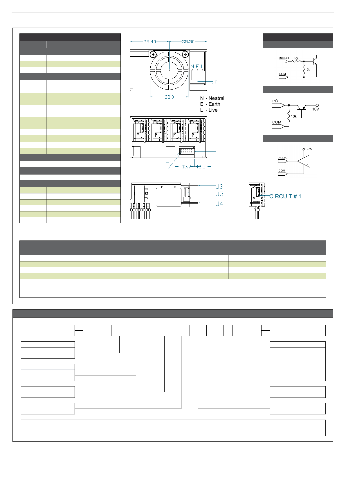
mains where no neutral is present, connect the two live wires to L (Live) and N (Neutral) on the
input connector.
COOLING
For proper cooling of the power supply, the air intake and outlet must not be impeded. Allow 50mm clearance at both ends and position cabling appropriately.
EARTH TERMINAL
MARKING
To comply with the requirements of IEC/EN/UL/CSA 62368-1, IEC/EN/UL/CSA 60950-1 & IEC/EN/UL/CSA 60601-1, where the incoming wiring earth is intended
for connection as the main protective earth conductor and where the terminals for such a connection is not supplied on a component or subassembly, the user
shall add an appropriate label displaying a protective earth symbol in accordance with IEC60417-5019 (2006-08) directly adjacent to the terminal. The label
should be durable and legible and should withstand the 15 second rub test as per UL60950-1 section 1.7.15.
WARRANTY
Contact your sales agent or Vox Power for product repairs. See Vox Power standard terms and conditions for warranty conditions.
PRODUCT LABELS
The external product label contains information relevant to the power system. The label contains input voltage, maximum input current, input frequency,
maximum output power, fuse rating and type, serial number, approvals and product part number in form NEVO+600xx-yyyy-zzz.
NEVO+ OUTPUT
MODULES
Each output module label contains information relevant to that output. The label contains voltage adjustment range, maximum output current, serial number,
approvals and the part number in format OPx.
OTHER
•
A label warning that external surfaces are hot during operation and that the unit should be allowed to cool down properly should be placed on the unit
where such a label is clearly visible.
•The NEVO+600 series is designed to comply with EMC standards but it does not imply that the end system will comply.
•To prolong the life of the unit, use in dust free environment.
•Units can sometimes be damaged during transit. In the event of transit damage, DO NOT connect power to the unit. Contact your sales agent or Vox
Power.
•Always use adequately sized cables and ensure good crimp connections. Use cable supports to minimise stress on connectors.
•
Avoid excessive shock or vibration.

Page 2of 4Vox Power Limited | Unit 2, Red Cow Interchange Estate, Ballymount, Dublin 22, D22 Y8H2, Ireland | T +353 1 4591161 | www.vox-power.com
DOC-MN-001-05, NEVO+600 Series Installation Manual
Specifications
INPUT MODULE SPECIFICATION SUMMARY
Parameter
Details
Min
Typical
Max
Units
AC Input Voltage
Nominal range is 100V
RMS
to 240V
RMS
85
264
V
RMS
AC Input Frequency
Contact factory for 400Hz operation.
47
50/60
63
Hz
DC Input Voltage3
Standard (S/SL)
Medical (M/ML)
120
120
370
300 VDC
Output Power Rating
Standard & Medical (S/M) - De-rate linearly from 600Watts at 120V
RMS
to 450Watts at 85V
RMS
Low Noise (SL/ML) - De-rate linearly from 450Watts at 120VRMS to 338Watts at 85VRMS
600
450 Watts
Input Current
Standard & Medical (S/M) - 600Watts output at 120Vrms input
Low Noise (SL/ML) - 450Watts output at 120Vrms input
6
5 Amps
Fusing
Live line fused (5x20 Fast acting)
8
Amps
Power Factor
Typical value for 300 Watts output at 240Vrms input
0.96
0.99
Size
133.7 (L) x 77.7 (W) x 41.0 (H). See diagram for tolerance details
mm
Weight
360 + 60 per output module
Grams
Notes
1. NEVO+ input modules can only be used with NEVO+ output modules and must not be used for any other purpose.
2. Only use a power source of the type indicated on the product label.
3. Not covered by safety approvals. Contact Vox Power.
OUTPUT MODULE SPECIFICATION SUMMARY
MODEL Output Voltage Output
Current
Rated
Power
Peak
Power
Load
Reg.
Line
Reg.
Cross
Reg.
Ripple &
Noise FPMH (1) Feature
Set (2)
Min.
Nom.
Max.
OP1
1.5V
5V
7.5V
25A
125W
187.5W
±50mV
±5mV
±10mV
50mV
PP
0.5
ABCDEFG
OP2
4.5V
12V
15V
15A
150W
225W
±100mV
±12mV
±24mV
120mV
PP
0.5
ABCDEFG
OP3
9V
24V
30V
7.5A
150W
225W
±150mV
±24mV
±48mV
240mV
PP
0.5
ABCDEFG
OP4
18V
48V
58V
3.75A
150W
217.5W
±300mV
±48mV
±96mV
480mV
PP
0.5
ABCDEFG
OP5
3.3V
12V
15V
5A
2x 75W
2x 75W
±50mV
±12mV
±24mV
240mV
PP
0.75
AFG
OP8
23.2V
24V
24.7V
3.125A
2x 75W
2x 75W
±100mV
±24mV
±48mV
480mV
PP
0.75
AFG
OPA2(3)
4.5V
12V
15V
25A
300W
375W
±100mV
±12mV
±24mV
120mV
PP
0.5
ABCDEFGH
OPA3(3)
9V
24V
30V
15A
300W
450W
±150mV
±24mV
±48mV
240mV
PP
0.5
ABCDEFGH
Note 1.
Output module, 30˚C base, 100% load, SR332 issue 2 Method I, Case 3, Ground, Fixed, Controlled
Note 2.
Note 3.
A = Remote Sense, B = External Voltage control, C = External constant current control, D = Current output signal, E = Current share, F =Over Voltage protection,
G = Over temperature protection, H = Dual Slot module
Can only be used with NEVO+600 chassis with date codes from 2048 onwards. eg. 2048C080000 can use A2 or A3 module, 2047C089999 cannot use A2 or A3 module.
SAFETY SPECIFICATIONS
Parameter Details Max Units
Isolation Voltages
Input to Output (2 MOPP). Do not perform test on assembled unit(1)
4000
V
AC
Input to Chassis (1 MOPP)
1500
V
AC
Global signals (J2) to Output/Chassis
250
V
DC
Output to Output/Chassis (Standard modules)
250
V
DC
Earth Leakage Current
INDUSTRIAL: Normal condition, 264Vac, 63Hz, 25°C
1500
uA
MEDICAL: Normal condition, 264Vac, 63Hz, 25°C
300
uA
Touch Leakage Current
Standard modules NC/SFC
20/200
uA
Patient Leakage Current
Standard modules 264Vac, 63Hz, 25°C NC/SFC
(2)
-----
uA
Note 1. Testing an assembled unit to 4000V
AC
may cause damage. Please refer to application note (APN-002) on Vox Power website or contact Vox Power representative.
Note 2. Not Applicable
INSTALLATION SPECIFICATIONS
Parameter Details Parameter Details
Equipment class
I
Flammability Rating
94V-2
Overvoltage category
II
Ingress protection rating
IP10
Material Group
IIIb (indoor use only)
ROHS compliance
2011/65/EU
Pollution degree
2
Intended usage environment
Home Healthcare (M/ML)/ Industrial (S/SL)
ENVIRONMENTAL SPECIFICATIONS
Parameter Details Non-Operational Operational Units
Min Max Min Max
Air Temperature
Operational limits subject to appropriate de-ratings
-40
+85
-20
70(1)
°C
Humidity
Relative, non-condensing
5
95
5
95
%
Altitude
-200
5000
-200
5000(2)
m
Air Pressure
52
106
52(2)
106
kPa
Noise Level
Standard Versions (S/M) - Variable. Measured 1m from fan intake.
-
-
36
60
dBA
Low Noise Versions (SL/ML) - Variable. Measured 1m from fan intake.
-
-
18
42
Shock
3000 bumps at 10G (16ms) half sine wave
Vibration
1.5G 10 to 200Hz sine wave, 20G for 15min in 3 axes random vibration
Notes
1. Derate input and all outputs at 2.5%/°C above 50°C.
2. 3000m & 68kPa for IEC/UL60601-1.

Page 3of 4Vox Power Limited | Unit 2, Red Cow Interchange Estate, Ballymount, Dublin 22, D22 Y8H2, Ireland | T +353 1 4591161 | www.vox-power.com
DOC-MN-001-05, NEVO+600 Series Installation Manual
Mechanical Dimensions and Mounting
SCREWS
Location
Details
Penetration
Tightening
Output Module Mount: 2 per module M3 POZI CSK 5mm max length 0.5NM
Input module Mount: MH1 – 3 (Bottom)
MH4 - 5 (Side) M4
4mm max, including chassis
0.5NM
Top Cover Mount:
5x M3 POZI CSK
1x M2.5 POZI CSK
5mm max length,
4mm max length 0.5NM
Unless stated otherwise, all dimensions are in millimetres and in accordance with DIN2768-1/2 CLASS C

Page 4of 4Vox Power Limited | Unit 2, Red Cow Interchange Estate, Ballymount, Dublin 22, D22 Y8H2, Ireland | T +353 1 4591161 | www.vox-power.com
DOC-MN-001-05, NEVO+600 Series Installation Manual
Connector details
PINOUTS
INTERNAL CIRCUITRY
Circuit
Details
INHIBIT
J1 – Mains Input
1
Live
2
Earth
3
Neutral
J2 – Global Signals
1
Slot A - Power Good
2
Slot A - Inhibit
POWER GOOD
3
Slot B - Power Good
4
Slot B - Inhibit
5
Slot C - Power Good
6
Slot C - Inhibit
7
Slot D - Power Good
8
Slot D - Inhibit
9
Global Inhibit (GINH)
10
AC OK
AC OK
11
+5V (Bias Supply 1A)
12
COM
J3 - Output Power
Positive Output
J4 - Output Power
Negative Output
J5(4) - Output Signals
1
- Sense
2
+ Sense
3
V
CONTROL
4
I
CONTROL
5
COM
6
+5V (Bias Supply 10mA)
MATING CONNECTORS
Ref.
Details
Manufacturer
Housing
Terminal
J1 - Mains Input
3 Pin, 5.08mm with friction lock, 18-24AWG
MOLEX(2)
010013036
8701031
J2 - Global Signals
12 Pin, 2mm, 24-30 AWG, WIRE TO BOARD
MOLEX(2)
0511101251
0503948051
J3,4(1) – Output Power Faston/Quick-Connect Tab – Size 6.35x0.8mm VARIOUS(2) VARIOUS
J5 - Output Signals
6 PIN, 1.25mm, with Friction Lock, 28-30AWG
MOLEX(2)
1510210600
50058800
Notes
1. Terminal and wire current rating must exceed maximum short circuit output current. Eg. Output 1 = 25A*1.25 = 31.25Amps
2. Direct equivalents may be used for any connector parts.
3. All cables must be rated 105°C min, equivalent to UL1015.
4. Pinout is for single output types only.
PART NUMBERS AND ORDERING INFORMATION
Series name
NEVO+600 M L - 1 1 2 3 - 0 0 0
Factory Use
Leakage Current
M = Medical, S = Industrial
Use '0' for unused slots.
Blanking plates will be
inserted at factory.
Fan
Blank = Standard,
L = Low Noise
Slot A - Output #
Slot D - Output #
Slot B - Output #
Slot C - Output #
Industrial input module has ITE approvals (IEC60950 & IEC62368), Medical input module has medical approvals (IEC60601)
Contact your Distributor or Vox Power for special configuration requirements. The factory may allocate a 3 digit suffix to identify such requirements.
When ordering an input unit with no outputs inserted, use NEVO+600M/ML or NEVO+600S/SL.
Unless stated otherwise, all dimensions are in millimetres and in accordance with DIN2768-1/2 CLASS C
-
+
Circuit # 2
Circuit # 1
J2
Other manuals for NEVO+600 Series
1
Other Vox Power Power Supply manuals

Vox Power
Vox Power VCCM600S Series User manual

Vox Power
Vox Power VCCR300 Series User manual

Vox Power
Vox Power NEVO+ Series User manual

Vox Power
Vox Power VCCM600 Series User manual

Vox Power
Vox Power NEVO 600S Series User manual

Vox Power
Vox Power Nevo+ 1200 series User manual

Vox Power
Vox Power VCCM600S Series User manual

Vox Power
Vox Power NEVO+1200 Series User manual

Vox Power
Vox Power NEVO Plus 1200 Series User manual

Vox Power
Vox Power VCCM600 Series User manual