10
EN
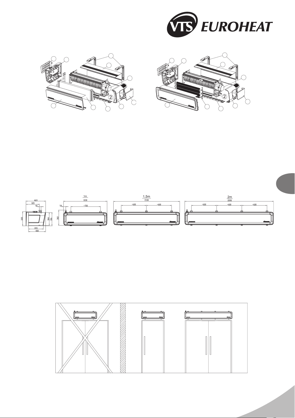
DEFENDER 100-200 WHN
DEFENDER 100-200 EHN
4. ELEMENTS OF AUTOMATICS.
Electrical connections can be carried out only by qualied electricians, according to the binding regulations of:
● industrial safety;
● sssembly instructions;
● technical documentation for each individual element of automatics.
IMPORTANT! Study the original documentation delivered together with the elements of automatics, prior to the commencing of assembly and connecting of the system.
MODEL DIAGRAM TECHNICAL DATA COMMENTS
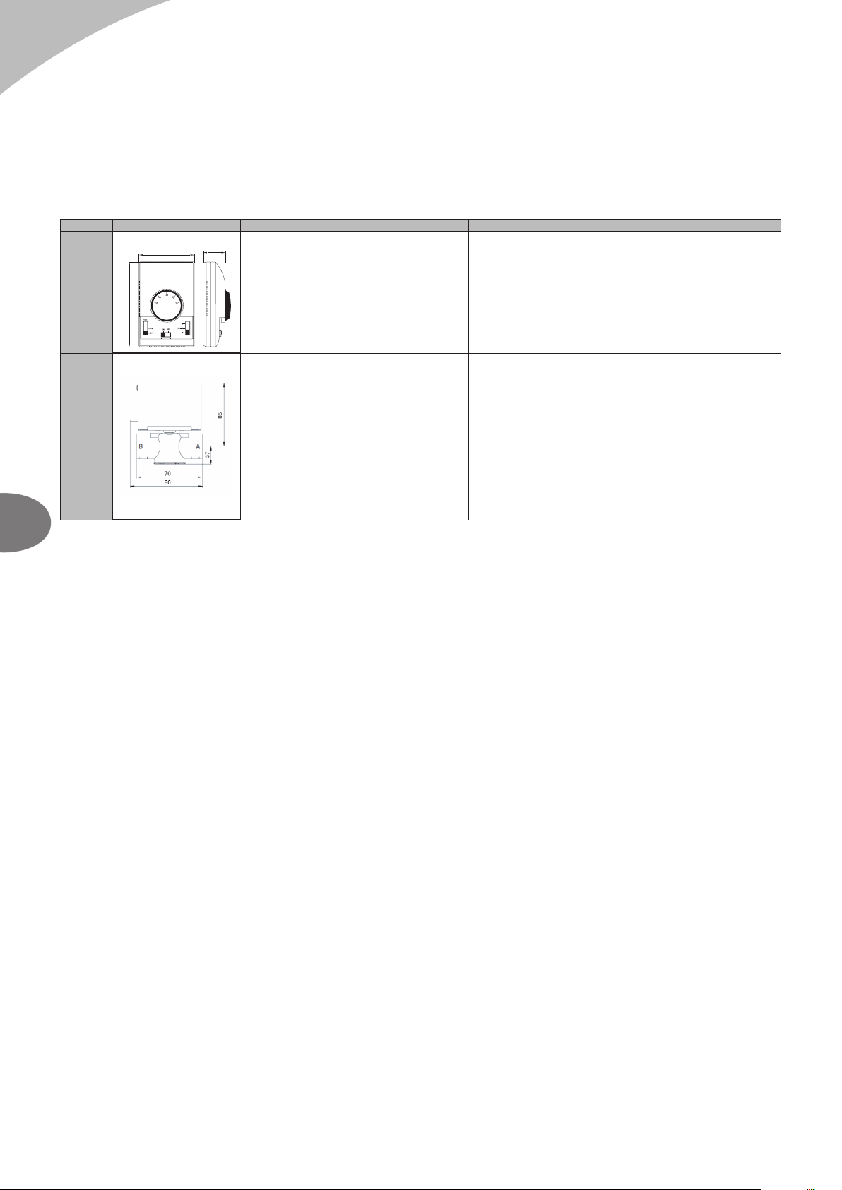
WALL-MOUNTED DX
CONTROLLER
87 35
133
WALL-MOUNTED DX CONTROLLER
● Supply voltage: 220-240 VAC
● Permissible initial current: 6(3A)
● Range of regulation: 10-30°C
● Accuracy of regulation: +/- 1°C
● Level of protection: IP 30
● Assembly method: on plastered walls
● Parameters of working environment: from -10 to +50°C
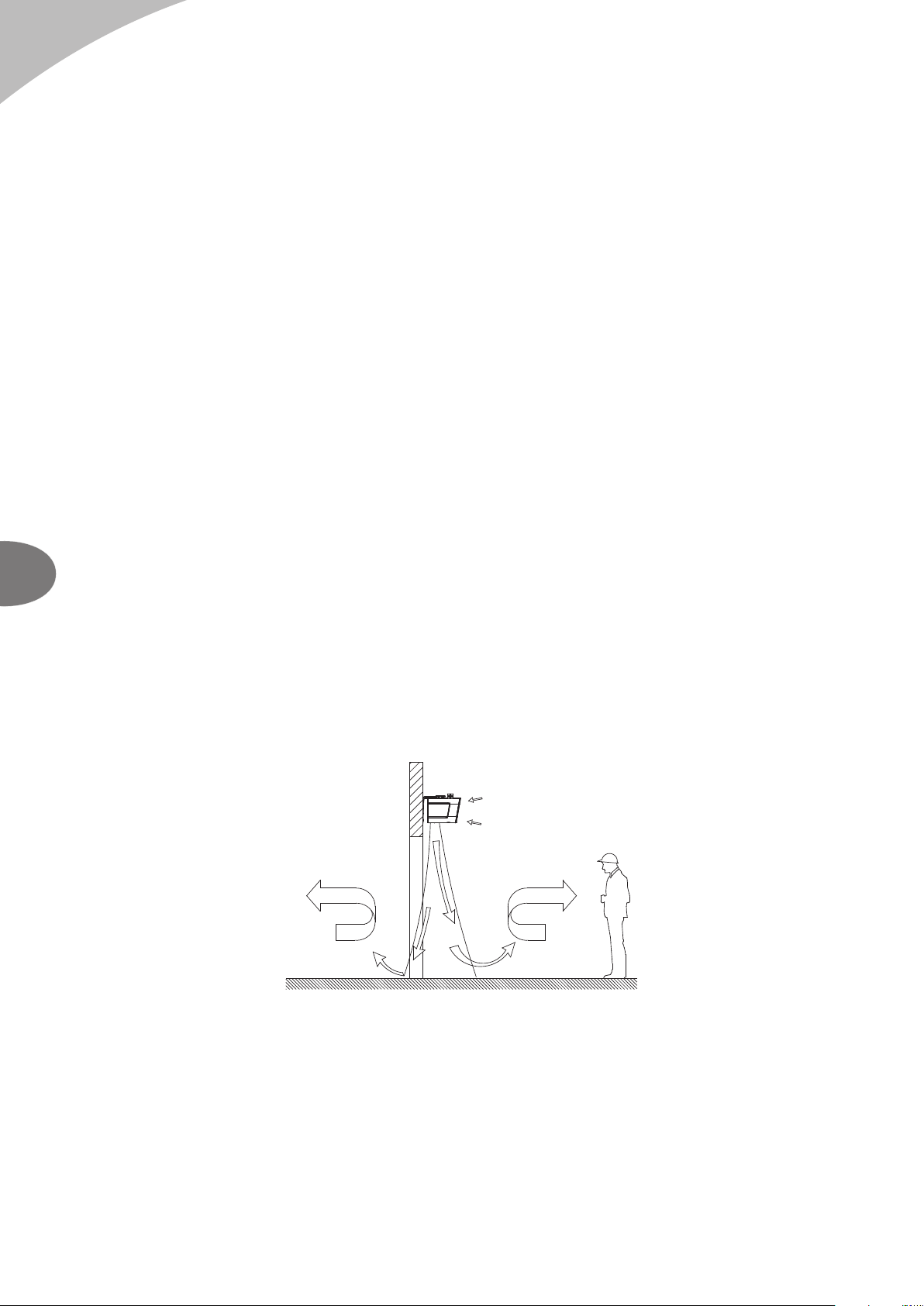
● One wall-mounted DX controller can support the maximum of 1 curtain of the
WHN, or EHN type.
● The maximum length of the conductor, from the curtain to the programming
device, is 100 m.
● It is recommended to make a connection using a conductor of the min. size 5 x
1 mm2 or 6 x 1mm2 depend on the option of connection (see the schemes)
● The drawings with the elements of automatics contain only visualisations of
sample products.
● The controller does not constitute an integral part of the curtain. It is an
optional device, which may be replaced with any programming device or
switch that conforms to the 60335 standard.
TWO-WAY VALVE WITH ACTUATOR
TWO-WAY VALVE
●Connection diameter: 3/4”
●Operation mode: on/off
●Maximum differential pressure 100 kPa
●Pressure degree PN 16
●Airow degree factor kvs: 6.5 m3/h
●Maximum heat agent temperature: 93°C
●Work environment parameters: 2 …40°C
VALVE ACTUATOR
●Power consumption 7 VA
●Power supply voltage: 230 V AC +/- 10%
●Closing/opening time 5/18s
●Item without supply: closed
●Type of protection: IP20
●Work environment parameters: 2 … 40°C
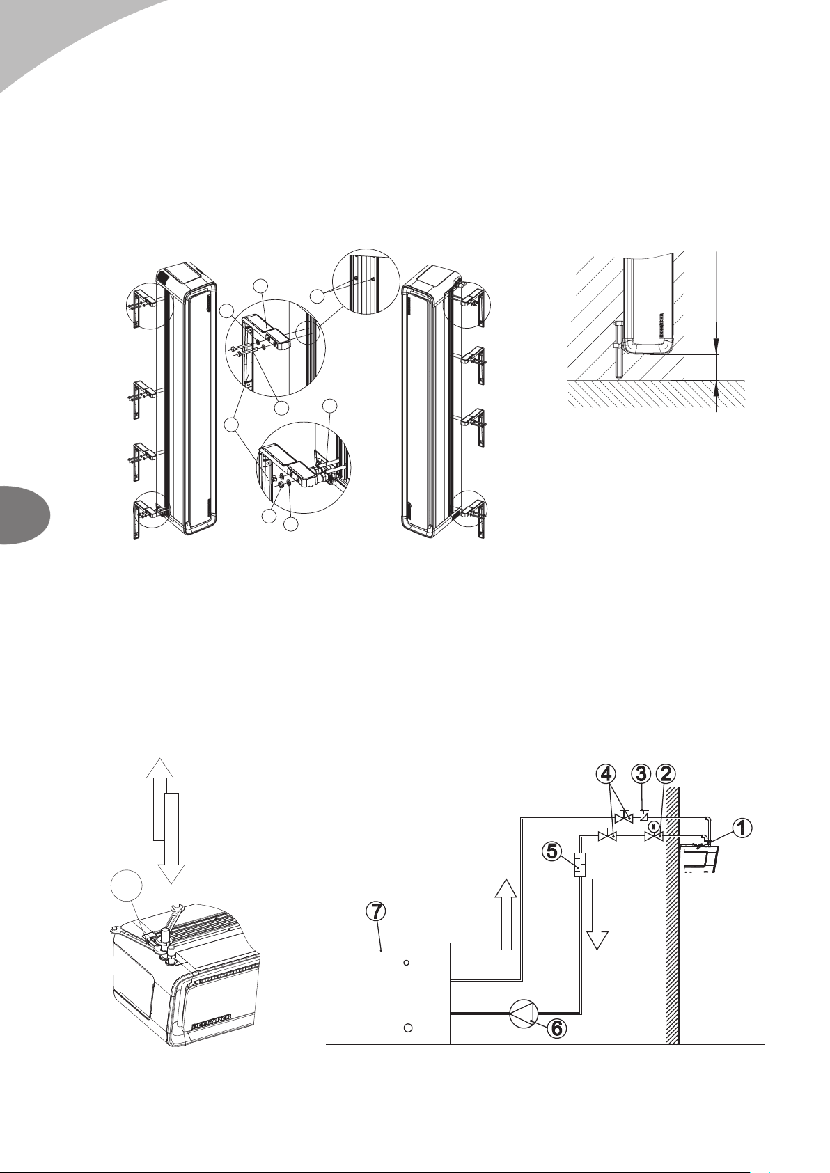
●Two-way valve should be installed on the return (outlet) pipeline.
●Automation element drawings are only a visualisation of sample products.
●Power connection should be done with a cable min. 3 x 0.75 mm2.
●Automation element drawings are only a visualisation of sample products.
IMPORTANT! If required, the conductors that belong to additional elements of control automatics (thermostat, door switch, wall-mounted controller) should be installed in separate cable
channels, out-of-parallel to the supply conductors.
5. START-UP, OPERATION, MAINTENANCE
5.1. START-UP/PUTTING INTO OPERATION
● Prior to the commencing of any installation or maintenance work, disconnect power supply and secure it against unintentional reactivation.
● It is recommended to use lters in the hydraulic system. It is recommended to clean/rinse the system, draining a few litres of water, prior to the connecting of hydraulic conduits (the supply conduits,
in particular).
● It is advised to use vent valves in the highest point of the system.
● It is recommended to install shut-off valves directly after the device, should the disassembly of the device be necessary.
● All protective equipment is to be installed before the pressure increases, according to maximum the permissible pressure rating of 1.6MPa.
● Hydraulic connection should be free of any stresses and loads.
● Check the correctness of hydraulic connections (leak-tightness of the vent, collecting pipes, correctness of ttings installation), prior to the initial start-up of the device.
● It is recommended to check the correctness of electrical connections (of automatics, power supply), prior to the initial start-up of the device. It is advised to use an additional, external residual-
current protection.
IMPORTANT! All connections should be carried out, according to this technical documentation and the documentation delivered with automation equipment.
5.2. OPERATION AND MAINTENANCE
● It is advised to carefully analyse all the operational and assembly guidelines listed in chapter 3 and 4.
● The casing of the device does not require maintenance.
● The heat exchanger should be cleaned on a regular basis from dust and fat deposit. It is especially recommended to clean the exchanger before the heating season with the use of compressed air
from the air intake side (after removing the front panel). You should pay special attention to the exchanger's lamellae which are very delicate.
● Should the lamellas be deformed (bent), straighten them with a special tool.
● The fan's motor does not require any exploitation service, the only service activities that may be necessary concern cleaning the air intakes from dust and fat deposit.
● Disconnect phase voltage, if the device is shut down for longer periods of time.
● The heat exchanger does not have any anti-freezing protections.
● It is recommended to provide a periodical purging of the heat exchanger, preferably using compressed air.
● Should the temperature in the room drop below 0°C, with a simultaneous drop of the heating medium temperature, there is a risk that the heat exchanger might freeze (crack).
● The level of air pollutants should meet the criteria allowable concentrations of pollutants in indoor air, for non-industrial areas, the level of dust concentration up to 0.3 g / m³.
● It is forbidden to use device for the duration of the construction works except for the start-up of the system.
● The equipment must be operated in rooms used throughout the year, and in which there is no condensation (large uctuations in temperature, especially below the dew point of the moisture
content). The device should not be exposed to direct UV rays.
● The device should be operated at the supply water temperature up to 90 °C with working fan.