VTS Euroheat DEFENDER 100 WHN Guide

EN Technical Documentation
ES Documentación Técnica
DEFENDER 100-200 WHN
DEFENDER 100-200 EHN
DR-ver.1.5 (01.2013)

DEFENDER 100-200 WHN
DEFENDER 100-200 EHN

EN
ES:
TABLE OF CONTENTS
1. INTRODUCTION ...............................................................................................................................................................................................................................................................................................5
1.1. PRECAUTIONS, REQUIREMENTS, RECOMMENDATIONS ....................................................................................................................................................................................................................5
1.2. TRANSPORT ..............................................................................................................................................................................................................................................................................................5
1.3. INITIAL STEPS TAKEN BEFORE THE INSTALLATION ............................................................................................................................................................................................................................5
2. STRUCTURE, INTENDED USE, PRINCIPLE OF OPERATION .......................................................................................................................................................................................................................5
2.1. INTENDED USE .........................................................................................................................................................................................................................................................................................5
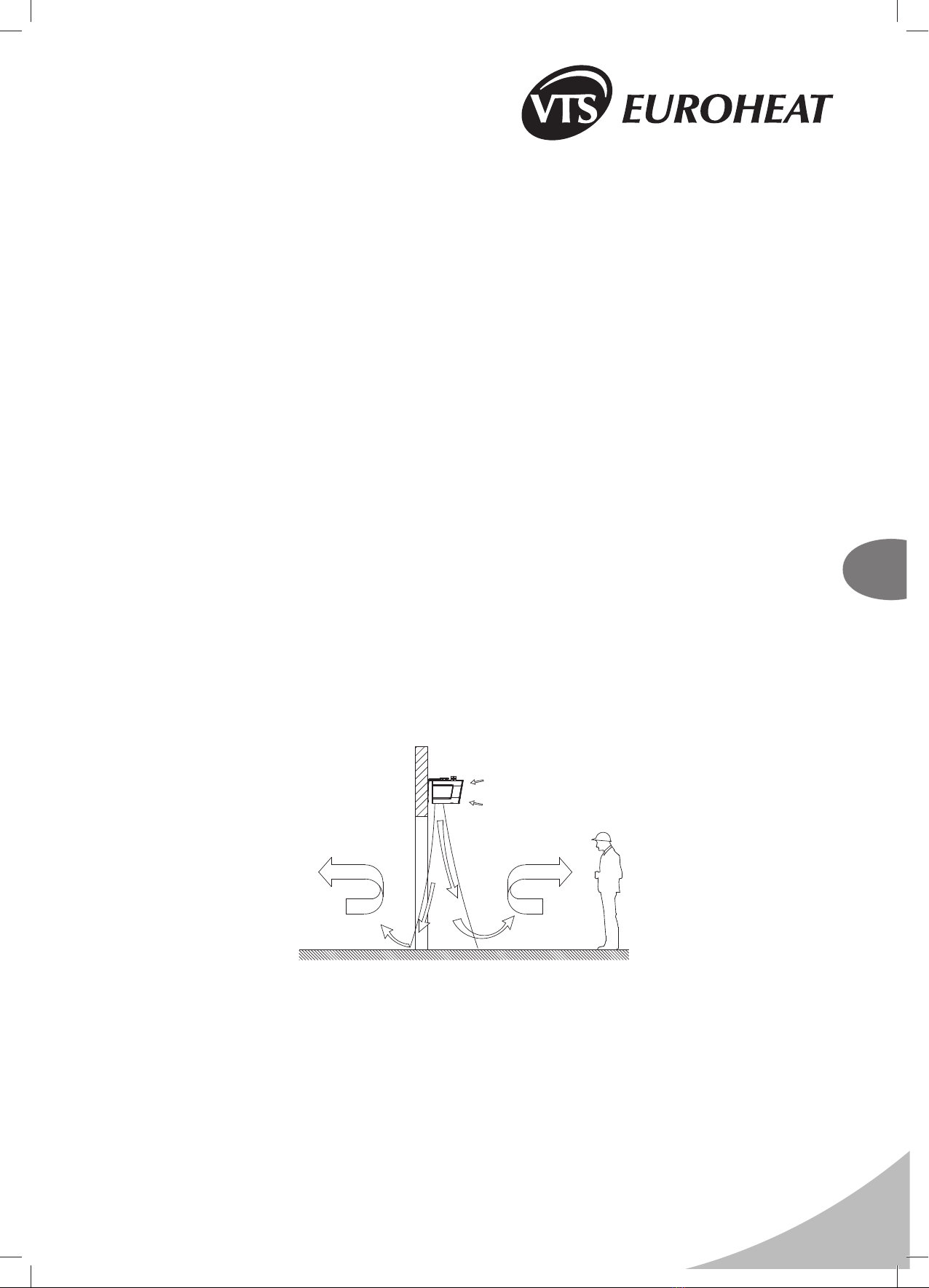
2.2. PRINCIPLE OF OPERATION .....................................................................................................................................................................................................................................................................5
2.3. STRUCTURE (DEFENDER 100-200 WHN, EHN) .....................................................................................................................................................................................................................................5
2.4. OVERALL DIMENSIONS (DEFENDER 100-200 WHN, EHN) ...................................................................................................................................................................................................................6
3. ASSEMBLY ........................................................................................................................................................................................................................................................................................................6
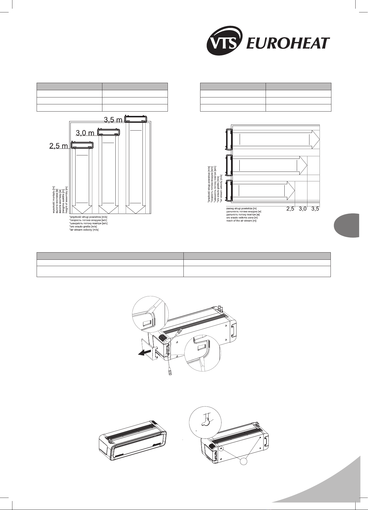
3.1. ASSEMBLY/ DISASSEMBLY OF SIDE COVERS ......................................................................................................................................................................................................................................7
3.2. ASSEMBLY OF DEVICE .............................................................................................................................................................................................................................................................................7
3.2.1. HORIZONTAL ASSEMBLY DIRECTLY ON THE WALL. ...................................................................................................................................................................................................................7
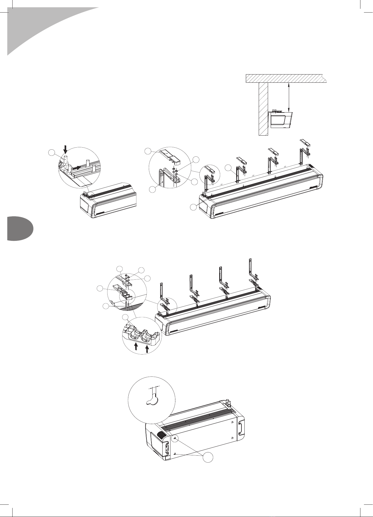
3.2.2. HORIZONTAL ASSEMBLY WITH USING INSTALATION HANDLES. ..............................................................................................................................................................................................8
3.2.3. VERTICAL ASSEMBLY DIRECTLY ON THE WALL..........................................................................................................................................................................................................................8
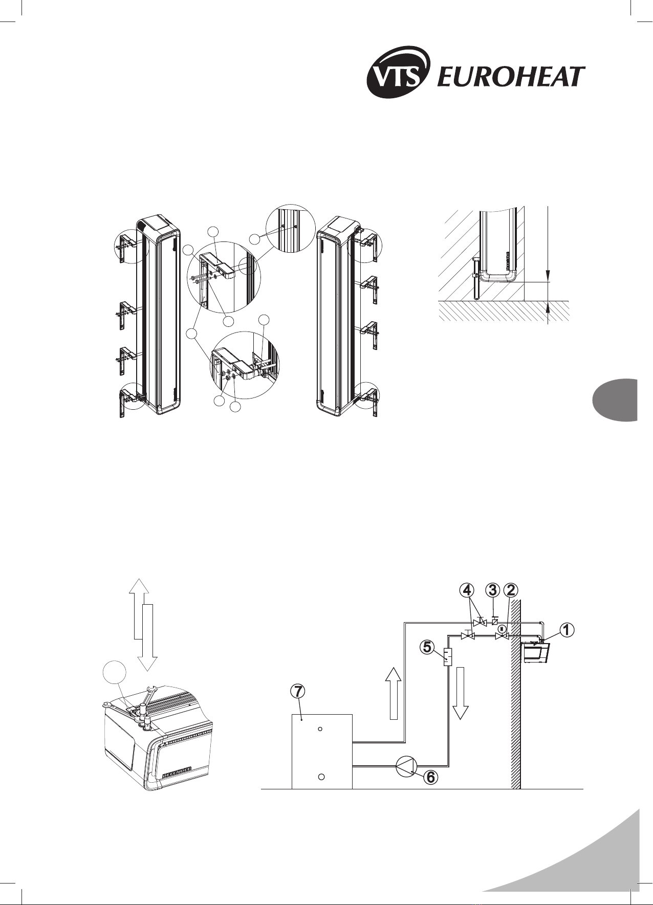
3.2.4. VERTICAL ASSEMBLY WITH USING INSTALATION HANDLES.....................................................................................................................................................................................................9
3.3. ASSEMBLY AND INSTALLATION GUIDELINES ........................................................................................................................................................................................................................................9
4. ELEMENTS OF AUTOMATICS .......................................................................................................................................................................................................................................................................11
5. START-UP, OPERATION, MAINTENANCE .................................................................................................................................................................................................................................................... 11
5.1. START-UP/PUTTING INTO OPERATION ................................................................................................................................................................................................................................................11
5.2. OPERATION AND MAINTENANCE .........................................................................................................................................................................................................................................................11
6. SERVICING .....................................................................................................................................................................................................................................................................................................12
6.1. PROCEDURE IN CASE OF DEFECTS ....................................................................................................................................................................................................................................................12
6.2. COMPLAINT PROCEDURE .....................................................................................................................................................................................................................................................................13
7. INDUSTRIAL SAFETY INSTRUCTION ...........................................................................................................................................................................................................................................................13
8. TECHNICAL DATA ..........................................................................................................................................................................................................................................................................................23
8.1. WATER AIR CURTAIN – DEFENDER 100-200 WHN ..............................................................................................................................................................................................................................23
8.2. ELECTRIC AIR CURTAIN – DEFENDER 100-200 EHN ...........................................................................................................................................................................................................................25
9. ATTACHMENTS ..............................................................................................................................................................................................................................................................................................28
9.1. ELECTRICAL DIAGRAM OF DEFENDER 100-200 WHN.........................................................................................................................................................................................................................29
9.2. ELECTRICAL DIAGRAMS OF DEFENDER 100-200 EHN.......................................................................................................................................................................................................................30
9.3. ELECTRICAL DIAGRAMS OF CONNECTION OF DEFENDER 100-200 WHN CONTROL SYSTEM - CONTROL WITH USING A WALLMOUNTED DX CONTROLLER .........................................35
9.4. ELECTRICAL DIAGRAMS OF CONNECTION OF DEFENDER 100-200 WHN CONTROL SYSTEM - CONTROL WITH USING A WALL-MOUNTED DX CONTROLLER
AND A DOOR SENSOR..................................................................................................................................................................................................................................................................................36
9.5. ELECTRICAL DIAGRAMS OF CONNECTION OF DEFENDER 100-200 EHN CONTROL SYSTEM - CONTROL WITH USING A WALLMOUNTED DX CONTROLLER ..........................................37
9.6. ELECTRICAL DIAGRAMS OF CONNECTION OF DEFENDER 100-200 EHN CONTROL SYSTEM - CONTROL WITH USING A WALL-MOUNTED DX CONTROLLER
AND A DOOR SENSOR..................................................................................................................................................................................................................................................................................38
10. TECHNICAL INFORMATION TO THE REGULATION (EU) NO 327/2011 IMPLEMENTING DIRECTIVE 2009/125/EC ..............................................................................................................................39
11. SERVICING ....................................................................................................................................................................................................................................................................................................41
TABLA DE CONTENIDOS
1. INTRODUCCIÓN .............................................................................................................................................................................................................................................................................................14
1.1. PRECAUCIONES, REQUERIMIENTOS, RECOMENDACIONES ...........................................................................................................................................................................................................14
1.2. TRANSPORTE ..........................................................................................................................................................................................................................................................................................14
1.3. MEDIDAS ADICIONALES TOMADAS ANTES DE LA INSTALACIÓN .....................................................................................................................................................................................................14
2. ESTRUCTURA, USO PREVISTO, PRINCIPIO DE FUNCIONAMIENTO .......................................................................................................................................................................................................14
2.1. USO PREVISTO .......................................................................................................................................................................................................................................................................................14
2.2. PRINCIPIO DE OPERACIÓN ...................................................................................................................................................................................................................................................................14
2.3. ESTRUCTURA (DEFENDER 100-200 WHN, EHN) .................................................................................................................................................................................................................................14
2.4. DIMENSIONES TOTALES (DEFENDER 100-200 WHN, EHN) ...............................................................................................................................................................................................................15
3. MONTAJE ........................................................................................................................................................................................................................................................................................................15
3.1. MONTAJE/DESMONTAJE DE CUBIERTAS LATERALES .......................................................................................................................................................................................................................16
3.2. MONTAJE DE DISPOSITIVOS .................................................................................................................................................................................................................................................................16
3.2.1. MONTAJE HORIZONTAL DIRECTO AL MURO .............................................................................................................................................................................................................................16
3.2.2. MONTAJE HORIZONTAL CON USO DE SOPORTES DE INSTALACIÓN ....................................................................................................................................................................................17
3.2.3. MONTAJE VERTICAL DIRECTO AL MURO ...................................................................................................................................................................................................................................17
3.2.4. MONTAJE VERTICAL CON USO DE SOPORTES DE INSTALACIÓN .........................................................................................................................................................................................18
3.3. GUÍAS PARA EL MONTAJE E INSTALACIÓN .........................................................................................................................................................................................................................................18
4. ELEMENTOS DE AUTOMATIZACIÓN ............................................................................................................................................................................................................................................................20
5. INICIO, OPERACIÓN Y MANTENIMIENTO ....................................................................................................................................................................................................................................................20
5.1. INICIO/ PUESTA EN MARCHA .................................................................................................................................................................................................................................................................20
5.2. OPERACIÓN Y MANTENIMIENTO ..........................................................................................................................................................................................................................................................20
6. SERVICIO .......................................................................................................................................................................................................................................................................................................21
6.1. PROCEDIMIENTO EN CASO DE DESPERFECTOS ..............................................................................................................................................................................................................................21
6.2. PROCEDIMIENTO DE RECLAMOS ........................................................................................................................................................................................................................................................22
7. INSTRUCCIONES DE SEGURIDAD INDUSTRIAL ........................................................................................................................................................................................................................................22
8. DATOS TÉCNICOS .........................................................................................................................................................................................................................................................................................23
8.1. CORTINA DE AIRE AGUA – DEFENDER 100-200 WHN ........................................................................................................................................................................................................................23
8.2. CORTINA DE AIRE ELÉCTRICA – DEFENDER 100-200 EHN ................................................................................................................................................................................................................25
9. ARCHIVOS ADJUNTOS ..................................................................................................................................................................................................................................................................................28
9.1. ESQUEMAS ELÉCTRICOS DEFENDER 100-200 WHN..........................................................................................................................................................................................................................29
9.2. ESQUEMAS ELÉCTRICOS DEFENDER 100-200 EHN...........................................................................................................................................................................................................................30
9.3. ESQUEMAS ELÉCTRICOS DE LAS CONEXIONES DEL SISTEMA DE CONTROL DEFENDER 100-200 WHN
– CONTROL CON USO DE UN CONTROLADOR MONTADO A LA PARED DX .........................................................................................................................................................................................35
9.4. ESQUEMAS ELÉCTRICOS DE LAS CONEXIONES DEL SISTEMA DE CONTROL DEFENDER 100-200 WHN
– CONTROL CON USO DE UN CONTROLADOR MONTADO A LA PARED DX Y UN SENSOR EN LA PUERTA ......................................................................................................................................36
9.5. ESQUEMAS ELÉCTRICOS DE LAS CONEXIONES DEL SISTEMA DE CONTROL DEFENDER 100-200 EHN
– CONTROL CON USO DE UN CONTROLADOR MONTADO A LA PARED DX .........................................................................................................................................................................................37
9.6. ESQUEMAS ELÉCTRICOS DE LAS CONEXIONES DEL SISTEMA DE CONTROL DEFENDER 100-200 EHN
– CONTROL CON USO DE UN CONTROLADOR MONTADO A LA PARED DX Y UN SENSOR EN LA PUERTA ......................................................................................................................................38
10. INFORMACIÓN TÉCNICA A LA REGULACIÓN (EU) N° 327/2011 APLICACIÓN DE LA DIRECTIVA 2009/125/EC...................................................................................................................................40
11. SERVICIO.......................................................................................................................................................................................................................................................................................................42

DEFENDER 100-200 WHN
DEFENDER 100-200 EHN

5
EN
1. INTRODUCTION
1.1. PRECAUTIONS, REQUIREMENTS, RECOMMENDATIONS
Detailed analysis of this documentation, as well as assembly and use of equipment, according to the descriptions contained therein, and following all safety requirements, is the basis for the
correct and safe operation of the device. Any other use that contradicts this instruction may cause accidents with serious consequences. Unauthorised personnel should have limited access
to the device, while the personnel should be properly trained. The term operational personnel refers to people, who, as the result of completed training, own experience and knowledge of
important standards, documentation and provisions, concerning safety and working conditions, have been authorised to carry out necessary work and are able to recognise potential hazards
and avoid them. This technical documentation must be delivered together with the device. The documentation contains information concerning all possible configurations of air curtains.
Examples of air curtain assembly and installation, as well as activation, use, repair and maintenance. Provided that the device is operated according to the intended use, this documentation
contains a sufficient number of instructions, required by the qualified personnel. The documentation should be placed near the device and be readily available to the service team. The
manufacturer reserves the right to introduce changes to the instruction, as well as changes to the device that affect its operation, without prior notice. VTS POLSKA Sp. z o.o. shall bear no
responsibility for on-going maintenance, inspections, programming of equipment and damage, caused by standstills of equipment related to the waiting for warranty services, all and any
damage related to the Client’s property, other than the device in question, as well as malfunctions that result from incorrect installation or improper use of the device.
DO NOT COVER
WARNING: To avoid overheating - do not cover the device!
1.2. TRANSPORT
Prior to the installing and taking the device out of the cardboard box, it is required to check whether the cardboard box has not been damaged in any way and/or the adhesive tape (installed
at the company) has not been broken off or cut. It is recommended to check whether the device’s casing has not been damaged in transport. Should any of the above situation occur, please
contact us through telephone or e-mail: Tel. 0 801 080 073, email: [email protected], fax: (+48) 12 296 50 75.
The device should be transported by two people. Use appropriate tools, when transporting the device, so as to avoid the damaging of goods and potential hazard to health.
1.3. INITIAL STEPS TAKEN BEFORE THE INSTALLATION
Record the serial number of the device in the warranty card, prior to the commencement of the installation process. It is required to properly fill-in the warranty card, after the completion of the
assembly. Prior to the commencing of any installation or maintenance work, it is required to disconnect power supply and protect it against unintentional activation.
2. STRUCTURE, INTENDED USE, PRINCIPLE OF OPERATION
2.1. INTENDED USE
For the convenience of users as well as different types of installations in commercial and industrial facilities we have designed an air curtain in two different options and three sizes:
●a DEFENDER 100 WHN curtain 1.0m wide with a water heater (8-11 kW, 1880 m3/h)
●a DEFENDER 100 EHN curtain 1.0m wide with electric heaters (6 kW, 2150 m3/h)
●a DEFENDER 150 WHN curtain 1.5m wide with a water heater (13- 19,5 kW, 3570 m3/h)
●a DEFENDER 150 EHN curtain 1.5m wide with electric heaters (12 kW, 3500 m3/h)
●a DEFENDER 200 WHN curtain 2.0m wide with a water heater (19- 28 kW, 4890 m3/h)
●a DEFENDER 200 EHN curtain 2.0m wide with electric heaters (13,5 kW, 5000 m3/h)
The use of the DEFENDER 100-200 air curtain enables the leaving of the room door open, regardless of weather conditions, thus providing a protective barrier. The curtain also enables a
simultaneous keeping of the required heating comfort inside the room/facility. The modern design of the DEFENDER 100-200 air curtain is a result of its wide range of application. The places in which
it is possible to install the device include: malls, office buildings, supermarkets, cinema compleEHs, as well as shops, store-rooms, manufacturing facilities or warehouse rooms. Please notice that the
use of an air curtain not only provides a protective barrier, but also it is an additional heat source in the room. APPLICATION: warehouse rooms, warehouses, sports facilities,
supermarkets, religious buildings, hotels, clinics, pharmacies, hospitals, office buildings, manufacturing facilities. PRIMARY ADVANTAGES: protection of climatic conditions in the room,
reduction of heating/cooling costs, universal size, ability to work both in vertical and horizontal position; simple, quick and intuitive assembly.
2.2. PRINCIPLE OF OPERATION
DEFENDER 100-200 WHN - heating medium, for example hot heating water, returns heat through a heat exchanger with a wide heat-exchange surface, thus providing high heating output (8-
28 kW). A transverse fan (1120-5000 m3/h) sucks in the air in the room, and pumps it through the heat exchanger, back into the room. The jet of warm air is directed downstream at high velocity,
thus providing an air barrier.
DEFENDER 100-200 EHN - electric heaters (2000 and 1500W each) heat up, as a result of the flowing of electric current, and return the heat to the air; the air is blown off through the fan, which
sucks in the air in the room. A jet of warm air is directed downstream at high velocity, thus providing an air barrier.
COLD AIR HEATED AIR
2.3. STRUCTURE (DEFENDERA 100-200 WHN, EHN)
DEFENDER 100-200 WHN – WATER AIR
CURTAIN
1. Heat exchanger
2. Control system
3. Transverse fan
4. Casing
5. Outlet grille
6. Assembly jigs
7. Side cover
8. Side cap
DEFENDER 100-200 EHN – ELECTRIC
AIR CURTAIN
1. Electric heaters
2. Control system
3. Transverse fan
4. Casing
5. Outlet grille
6. Assembly jigs
7. Side cover
8. Side cap

6
EN
DEFENDER 100-200 WHN
DEFENDER 100-200 EHN
6
1
2
3
4
5
4
7
8
78
6
4
3
8
7
5
1
2
4
7
8
1. WATER HEATER - HEAT EXCHANGER: Maximum parameters of the heating agent for the heat exchanger are : 90°C, 1.6MPa. The aluminium and copper construction consists of copper
pipes of the coil and aluminium lamellae. The connection collectors (male thread ¾``) are located in the upper part of the casing. The optimum water exchanger has been adjusted to operate in
three positions: horizontal and vertical with pins going up or down. Appropriate lead of hydraulic connections makes it possible for the curtain to be assembled directly by the wall as close to the
door frame as possible. The air curtain with a water heater generates power from 8 to 28 kW.
ELECTRIC HEATER: it consists of 1, 2 or 3 sets of heater elements in the amount depending on the option (length) of a particular curtain. Each set consists of three heaters generating in total
the power of 6 and 4,5 kW, powered with 400 V voltage, connected in a star. Due to such technical solutions the heater is capable of generating the rated power ranging from 6kW (for a 1m wide
curtain) to 13,5 kW (for a 2m wide curtain).
2. CONTROL SYSTEM: it is equipped with an outlet on the connection clamp block X0 for DEFENDERA 100-200 WHN and on the X1 block for DEFENDERA 100-200 EHN for connecting an on-
wall controller as well as a valve actuator for DEFENDERA 100-200 WHN.
The system of DEFENDER EHN is equipped with a safety device in the form of a fuse in the 230 V AC circuit.
The algorithm of the system's operation anticipates the function of the fan's delayed switch-off lasting 30 seconds in order to cool the electric heater.
3. HORIZONTAL FAN: the maximum temperature of operation is 90°C, the rated voltage is 230 V/50 Hz. The motor protection level is IP20, F insulation class. The horizontal fan applied in the
device with an advanced profile of blades and impeller geometry made of plastic makes it possible to obtain air capacities up to 5000 m3/h. The control of the electric motor as well as thermal
protections of the winding has been coupled with the control system which resulted in increasing safety of operation. Due to optimum power of the motor the DEFENDER curtain is energy saving
and durable.
4. CASING: Made of high quality plastic material resistant to temperature up to 90°C.
5. INSTALLATION HANDLES: DEFENDER is characterized by simple, quick and aesthetic assembly that can be performed on a wall in both horizontal and vertical position. There are
from 2 to 4 installation handles attached (as an option) to the curtain (depending on the option (length). Connections of electric wires and water channels has been especially designed
not to interfere the general aesthetic values of the device. The name DEFENDER includes devices that are 1, 1.5 and 2 m long that, if necessary, can be additionally joined both
horizontally and vertically to achieve different air supply options: from the left to the right and the opposite. the reach of the air stream is up to 3.5 m.
2.4. OVERALL DIMENSIONS (DEFENEDER 100-200 WHN, EHN)
2m
1,5m
1m
3. ASSEMBLY
IMPORTANT!
●The place of assembly should be carefully selected, taking into account the occurring of potential loads or vibrations.
●Prior to all installation or maintenance work, disconnect power supply and secure it against unintentional reactivation.
●It is recommended to use filters in the hydraulic system. It is recommended to clean/rinse the system, draining a few litres of water, prior to the connecting of hydraulic conduits (the supply
conduits, in particular).
IMPORTANT!
The air is blown out of the curtain at high velocity, along the surface of the opening, thus creating a protective barrier. Air curtains should cover the entire width of the door opening, in order to
obtain the maximum performance of the curtain.
IT IS RECOMMENDED TO TAKE INTO ACCOUNT THE FOLLOWING PARAMETERS, WHEN ASSEMBLING THE CURTAIN:
The width of the door frame should be less or equal to the width of the supplied air stream, a single DEFENDER 100-200 100-200 unit – its door can be 1, 1.5 or 2m wide.
WRONG CORRECT

7
EN
The range of the air jet - assembly height
- horizontal installation - vertical installation
height of assembly [m] fan speed width of the door [m] fan speed
2,5 1 2,5 1
3,0 2 3,0 2
3,5 3 3,5 3
5-7 m/s*
2,2 m/s* 2,5 m/s* 2,6 m/s*
7-9 m/s*
9,6-11 m/s*
5-7 m/s*
2,2 m/s*
2,5 m/s*
2,6 m/s*
7-9 m/s* 9,6-11 m/s*
IMPORTANT! The heating output should be adjusted to the temperature inside the room, as well as the strength and direction of the wind outside. The primary criterion for the regulation of the
heating power is the temperature inside the room, near the door. Should a room thermostat be used, DEFENDER 100-200 activates the heating mode, depending on the temperature settings.
IMPORTANT! Please consider additional factors that affect device operation.
Factors that have a negative effect on curtain operation Factors that have a positive effect on curtain operation
doors or windows that are constantly open in the room, thus creating a draft presence of awning, roofs etc. on the outer side of the door
constant and open access to staircases, available through the room, the chimney draft
effect use of revolving doors
3.1. ASSEMBLY/ DISASSEMBLY OF SIDE COVERS
In order to remove the side cover you should carefully level the catches located on the back wall with the use of a screwdriver and pull it away. Having installed the device and connected it to
the electric supply put the cover back by clicking it on the catches.
3.2. ASSEMBLY OF DEVICE
The unit can be assembled directly or with using installation handles (available in option) on any base construction providing stable and firm support.
3.2.1. HORIZONTAL ASSEMBLY DIRECTLY ON THE WALL.
For mounting DEFENDER directly to the wall use the top holes (1) on the back of the unit. Fixing screws Ø6 mm thick (not included) should have head diameter of not more than 14mm.
1
O15
7
IMPORTANT! The minimum distance between the unit and the ceiling should be 0.3m.

8
EN
DEFENDER 100-200 WHN
DEFENDER 100-200 EHN
3.2.2. HORIZONTAL ASSEMBLY WITH USING INSTALATION HANDLES.
It is possible to assemble DEFENDER 100-200 do the wall horizontally in two options:
OPTION I: Assembling handles with their arms faced downwards. In this option you should first screw the installation handles to the
wall (1) and then at regular intervals (for a 1m curtain it is 2 installation hanles every 700mm, for 1.5m – three, 2m - four installation
handles every 600mm) so that the handles' arms are levelled.
Then slide 2 (DR -1m), 3 (DR-1.5m) or 4 (DR-2m) assembly screws (2) M10x20 in each of the two guide bars. Lift the curtain with
the screw faced upwards and assemble them in the handles. Put backing straps (3), tighten the nuts (4) and close the handle's
covers (5).
ATTENTION! The minimum distance between the unit and the ceiling should be 0.3m.
2
3
2
4
1
5
1
OPTION II: Assembling handles with their arms faced upwards.
The assembly consists in attaching the installation handles to the unit (1) at regular intervals as in OPTION I In order to do so you should slide 2 (DR -1m), 3 (DR-1.5m) or 4 (DR-2m) assembly screws
(2') M10x80 in each of the two guide bars and knock out holes (6) on the outside of covers (5) with the use of a hammer and a screw and then close the handles' covers (1). Put the handles on the
screws, put backing straps (3) and tighten the nuts (4).
In this assembly option you can first assemble the handles to the curtain and than screw the whole down to a wall.
ATTENTION! The minimum distance between the unit and the ceiling should be 0.3m.
3
4
1
5
2'
6
3.2.3. VERTICAL ASSEMBLY DIRECTLY ON THE WALL.
For mounting DEFENDER directly to the wall use the left or right hand side holes (1) (depend on hanging side) on the back of the unit. Fixing screws Ø6 mm thick (not included) should have head
diameter of not more than 14mm.
7
1
IMPORTANT! In case of vertical assembly the minimal distance between the device and the floor (150mm) for access to the water coil blowdown connection and the cable terminal should be provide.
min. 0,3m

9
EN
3.2.4. VERTICAL ASSEMBLY WITH USING INSTALATION HANDLES.
It is possible to assemble Defender to a wall vertically on both sides of the gate (with the motor on the bottom or on the top).
For this option it is not important if you screw the handles down to the unit first and then screw the whole down to the wall or first attach the handles to the wall and then screw the curtain down to the
handles.
In the case of vertical assembly you should use the provided screws M10x80 and M8x80. 1, 2, or 3 handles should be attached with the use of screws (2) M8x80, through a backing strap (3) to the
threaded sleeve (7) installed in the unit's guide bar (zoom A). The handle on the side of the exchanger's connection pins should be mounted on screws (2’) M10x80 slid in guide bars (as in the case
of horizontal assembly), put a backing strap (3') and tighten the nut (4) (zoom B).
IMPORTANT: In case of vertical assembly the minimal distance between the device and the floor (150mm) for access to the water coil blowdown connection and the cable terminal should be
provide.
A
B
B
A
B
A
7
3
3'
4
1
5
2'
2
min. 0,15m
IMPORTANT! The device is intended for the operation in dry rooms, eCDlusively. Thus, pay particular attention to the condensation of water vapour on engine elements, since it is not fitted
for operating in humid environment.
IMPORTANT! The DEFENDER 100-200 air curtains are not intended for the installation:
●Outdoors;
●In humid rooms;
●In rooms categorised as explosive environments;
●In rooms with very high levels of dustiness;
●In rooms with aggressive atmosphere (due to the presence of copper and aluminium structural elements in the heat exchanger and electric heaters).
IMPORTANT! The DEFENDER 100-200 EH air curtains are not intended for the installation on suspended ceilings.
3.3. ASSEMBLY AND INSTALLATION GUIDELINES
CONNECTING OF HEATING MEDIUM
Protect the heat exchanger terminal against the impact of the torque moment 1, when installing a pipeline transporting a heating medium. The weight of installed pipelines should not impose a load
on the heater’s terminals.
IMPORTANT! Pay particular attention to the leak-tightness of connections, when filing the hydraulic system. Make sure that the water flowing from a leaky connection does not leak to the
electric engine (at the vertical assembly)
IMPORTANT! It is recommended to use filters in the hydraulic system. It is recommended to clean/rinse the system, draining a few litres of water, prior to the connecting of hydraulic conduits
(the supply conduits, in particular).
1
VENTING OF DEVICE/DRAINING OF HEATING MEDIUM
The access to air vents / agent escapes is obtained by means of removing covers / hole plugs 1 and 2 depending on the way of assembling Defender. When using a 13 mm fork spanner or
screwdriver you should loose the screw of an appropriate service valve:
- venting: position A and B – service valve II with the flexible pipe, position C – service valve I,
- escape: position A – service valve I, position B – service valve I, position C – service valve II.
EXAMPLE OF HYDRAULIC SYSTEM
1. DEFENDERA 100-200 WH
2. VALVE WITH ACTUATOR
3. VENT VALVE
4. SHUT-OFF VALVE
5. FILTER
6. CIRCULATING PUMP
7. BOILER
SUPPLY
SUPPLY
RETURN
RETURN

10
EN
DEFENDER 100-200 WHN
DEFENDER 100-200 EHN
WORKING POSITION
NUMBER OF SERVICE VALVE
III
AHorizontal (air blown downstream) draining venting
BVertical (air blown from left to right) draining venting
CVertical (air blown from right to left) venting draining
II.
I.
1
2
IMPORTANT! While venting the exchanger you should pay special attention to securing the device against accidental penetration of water into electrical elements.
IMPORTANT! Follow the instruction below, when draining the heating medium:
●Close the shut-off valves before and after the device;
●Close the control valve;
●Unscrew the vent;
●Unscrew the drain;
●Wait until the exchanger has been completely emptied;
●Connect compressed air to the exchanger and blow away the remaining water;
●Close the drain and vent.
IMPORTANT! Remember to vent the heater, if it has been activated after a prior draining of the heating medium.
IMPORTANT! Pay particular attention to the leak-tightness of connections, when filing the hydraulic system. Make sure that the water flowing from a leaky connection does not leak to the
electric engine (at the vertical assembly).
CONNECTING OF POWER SUPPLY
IMPORTANT! The system must be equipped with protective equipment that guarantees the disconnecting of the device on all poles of the power source.
Connection to the electric system must be performed by a duly authorized and qualified person .Wire passes are located on the back side of the curtain : (1) – control wire packing , (2) – power
wire packing. The access to the terminal strip is obtained by means of removing the side cover (3) from the motor's side.
3
1
2
Recommended safety devices and wires
Device DEFENDER 100-200 WHN DEFENDER 100-200 EHN
1m 1,5m 2m 1m 1,5m 2m
Overload and short circuit protection gG 10A gG 16A gG 20A gG 25A
Differential current protection
IDN=30mA
typ AC lub A
IDN=30mA
typ AC lub A
IN=16A IN=40A
Power wire cross-section 3x1,5mm25x1,5mm25x2,5mm25x4,0mm2
IMPORTANT! The specification of cables and protections refers to unbounded arrangement of cables (basic execution of the E installation according to the PN-IEC 60364-5-523 standard). One
should always abide by the local laws and recommendations concerning device connection.
DEFENDER 100-200 is equipped with a terminal strip adjusted to an appropriate thickness of wires.
DEFENDER 100-200 EHN
DEFENDER 100-200 WHN
IMPORTANT!
●It is recommended to connect wires to the terminal strip with previously clamped appropriate clip ends.
●Make sure that the space around the place where the air is sucked in by the curtains, as well as around the exhaust grid, is free of any structural elements of the building, which might
hamper the flow of air (e.g. suspended ceilings, covering development, ventilating ducts etc.).

11
EN
4. ELEMENTS OF AUTOMATICS.
Electrical connections can be carried out only by qualified electricians, according to the binding regulations of:
●industrial safety;
●sssembly instructions;
●technical documentation for each individual element of automatics.
IMPORTANT! Study the original documentation delivered together with the elements of automatics, prior to the commencing of assembly and connecting of the system.
MODEL DIAGRAM TECHNICAL DATA COMMENTS
WALL-MOUNTED DX
CONTROLLER
87 35
133
WALL-MOUNTED DX CONTROLLER
●Supply voltage: 220-240 VAC
●Permissible initial current: 6(3A)
●Range of regulation: 10-30°C
●Accuracy of regulation: +/- 1°C
●Level of protection: IP 30
●Assembly method: on plastered walls
●Parameters of working environment: from -10 to +50°C
●One wall-mounted DX controller can support the maximum of 1 curtain of the
WHN, or EHN type.
●The maximum length of the conductor, from the curtain to the programming
device, is 100 m.
●It is recommended to make a connection using a conductor of the min. size 5 x
1 mm2 or 6 x 1mm2 depend on the option of connection (see the schemes)
●The drawings with the elements of automatics contain only visualisations of
sample products.
●The controller does not constitute an integral part of the curtain. It is an
optional device, which may be replaced with any programming device or
switch that conforms to the 60335 standard.
TWO-WAY VALVE WITH ACTUATOR
63
125
TWO-WAY VALVE
●Terminal diameter: 3/4”
●Mode of operation: two-way ON/OFF
●Maximum differential pressure: 100kPa
●Pressure class: PN 16
●Kvs flow ratio: 3.5 m3/h
●Maximum temperature of heating medium: 105°C
●Parameters of working environment: from 2 to 40°C
VALVE ACTUATOR
●Power consumption: 7 VA
●Supply voltage: 230VAC +/-10%
●Closing/opening time: 4-5/9-11 s
●Position without power: closed
●Level of protection: IP44
●Parameters of working environment: from 2 to 40°C
●It is recommended to install a two-way valve on the return pipeline.
●The drawings with the elements of automatics contain only visualisations of
sample products.
●It is recommended to connect the supply, using a conductor of the min. size
2x0.75 mm2.
●The drawings with the elements of automatics contain only visualisations of
sample products.
IMPORTANT! If required, the conductors that belong to additional elements of control automatics (thermostat, door switch, wall-mounted controller) should be installed in separate cable
channels, out-of-parallel to the supply conductors.
5. START-UP, OPERATION, MAINTENANCE
5.1. START-UP/PUTTING INTO OPERATION
●Prior to the commencing of any installation or maintenance work, disconnect power supply and secure it against unintentional reactivation.
●It is recommended to use filters in the hydraulic system. It is recommended to clean/rinse the system, draining a few litres of water, prior to the connecting of hydraulic conduits (the supply conduits,
in particular).
●It is advised to use vent valves in the highest point of the system.
●It is recommended to install shut-off valves directly after the device, should the disassembly of the device be necessary.
●All protective equipment is to be installed before the pressure increases, according to maximum the permissible pressure rating of 1.6MPa.
●Hydraulic connection should be free of any stresses and loads.
●Check the correctness of hydraulic connections (leak-tightness of the vent, collecting pipes, correctness of fittings installation), prior to the initial start-up of the device.
●It is recommended to check the correctness of electrical connections (of automatics, power supply), prior to the initial start-up of the device. It is advised to use an additional, external residual-
current protection.
IMPORTANT! All connections should be carried out, according to this technical documentation and the documentation delivered with automation equipment.
5.2. OPERATION AND MAINTENANCE
●It is advised to carefully analyse all the operational and assembly guidelines listed in chapter 3 and 4.
●The casing of the device does not require maintenance.
●The heat exchanger should be cleaned on a regular basis from dust and fat deposit. It is especially recommended to clean the exchanger before the heating season with the use of compressed air
from the air intake side (after removing the front panel). You should pay special attention to the exchanger's lamellae which are very delicate.
●Should the lamellas be deformed (bent), straighten them with a special tool.
●The fan's motor does not require any exploitation service, the only service activities that may be necessary concern cleaning the air intakes from dust and fat deposit.
●Disconnect phase voltage, if the device is shut down for longer periods of time.
●The heat exchanger does not have any anti-freezing protections.
●It is recommended to provide a periodical purging of the heat exchanger, preferably using compressed air.
●Should the temperature in the room drop below 0°C, with a simultaneous drop of the heating medium temperature, there is a risk that the heat exchanger might freeze (crack).

12
EN
DEFENDER 100-200 WHN
DEFENDER 100-200 EHN
6. SERVICING
6.1. PROCEDURE IN CASE OF DEFECTS
DEFENDER 100-200 WHN/EHN
Symptoms What to check Description
Leakage in the
DEFENDER 100-200
WHN heat exchanger
●Fitting of the heat exchanger terminals, using two keys acting in two opposite
directions (apply the keys on each terminal), which protects against the possibility
of internal breaking of the collecting pipes.
●Relation between the leaking and a potential mechanical damage to the
exchanger.
●Leaking of vent valve elements or drain plug.
●Parameters of the heating medium (pressure and temperature) should not
exceed the permissible values.
●Correctness of the draining of the exchanger.
●type of agent (it cannot be any aggressive substance Al or Cu active),
●Circumstances in which leaking occurred (e.g. during the trial/initial start-up of
the system; after having drained the heating medium, followed by the filling of
the system) and the external ambient temperature at the moment of the defect
taking place (freezing hazard to the exchanger).
●Potentially aggressive atmosphere (air) in the place of work (e.g. high
concentration of ammonia in the sewage-treatment plant).
●Pay particular attention to the possibility of the freezing of the heat
exchanger in the winter. 99% of leaks occur during start-up/pressure
checks. The rectifying of the defect consists in the pulling back of the
vent/drain valve.
The fan of the device
works too loudly
DEFENDER 100-200
WHN, EHN
●Installation of the device, according to the guidelines in the Operation and
Maintenance Documentation (among others, the distance from the ceiling). ●Minimum distance: 30 cm from the ceiling
●Correctness of the horizontal alignment of the device.
●Correctness of electrical connections and qualifications of
●Parameters of the supply current (among others: voltage, frequency).
●Incorrect covering of the curtain in the suspended ceiling.
●Noise in lower speeds (damaged winding).
●Noise present only in the higher speeds – blocking of the air outlet.
●Type of other equipment working in the facility (e.g. exhaust fans) – increasing
noise may be a result of several pieces of equipment working simultaneously.
●Louder operation of DEFENDER 100-200 devices may be a result of
inappropriate place of assembly : e.g. choking the fan or the acoustic
specifics of a room.
The fan in the device
is not operational
DEFENDER 100-200
WHN, EHN
●Correctness and quality of electrical connections and qualifications of the fitter.
●Parameters of the supply current (among others: voltage, frequency) on the
terminal block of the fan’s engine.
●Operational correctness of other pieces of equipment present in the facility.
●Correct fitting of the conduits on the engine side – information available from VTS
Service Department.
●Voltage on the PE conductor (if present, it may indicate a breakdown).
●The electrical connection of the device must be carried out, according to
the diagrams found in the Operation and Maintenance Documentation.
●Damage, incorrect connecting or fitting of a wall-mounted controller, other than the
DX contro ller
●It is recommended to check the device by means of connecting the curtain
directly to the power supply and forcing the electric motor's operation
by shorting appropriate clips of the device's terminal strip and then the
terminal strip in the controller.
Damaged casing of the
device
DEFENDER 100-200
WHN, EHN
●Circumstances in which the defect occurred: remarks on the bill of lading,
inventory issue, condition of cardboard).
●Should the casing be defective, it is required to present photos of the
cardboard and device, as well as photos that confirm the compliance
between the serial number on the device and cardboard. If the damage
was done in transport, it is necessary to prepare a proper statement by the
driver/forwarder that delivered the goods.
WALL-MOUNTED
DX CONTROLLER
does not work/is burnt
●Correctness and quality of electrical connections (tight clamping of conductorsin
electric terminals, cross-section and material of electric conductors) and the
qualifications of the fitter.
●Parameters of the supply current (among others: voltage, frequency).
●Operational correctness of the DEFENDER 100-200 device, when connected
directly to the power supply (ignoring the DX controller).
●Whether the user has not damaged the “hand-wheel”, e.g. by rotating it by 360˚,or
the switch, e.g. by keeping it in the intermediate position.
●It is recommended to check the device by means of connecting the curtain
directly to the power supply and forcing the electric motor's operation
by shorting appropriate clips of the device's terminal strip and then the
terminal strip in the controller.
Actuator does not open
the valve
●Correctness of electrical connections and qualifications of the fitter.
●Operational correctness of the thermostat (the characteristic “ticking” when
switching the device).
●Parameters of the supply current (among others: voltage).
●It is of the highest importance to verify whether the actuator reacted to
alectrical impulse within 11 seconds. If you observe any damage of the
actuator you should make a complaint concerning the damaged element
and switch the actuator's operation mode to 'manual' - MAN which will
result in mechanical (permanent) opening of the valve.
The thermostat in the
DX controller does not
send any signal to the
actuator
●Correctness of electrical connections and qualifications of the fitter.
●Operational correctness of the thermostat (the characteristic “ticking” when
switching the device).
●Operational correctness of the actuator.
●Parameters of the supply current (among others: voltage).
●Place of thermostat/actuator installation in the room.
●If the “ticking” sound is not heard, the thermostat has been mechanically
damaged and should be subject to the complaint procedure. The
thermostat can also be installed in an improper space, which is subject to
temperature monitoring.
It is forbidden to place, dispose of and store worn-out electric and electronic equipment, together with other waste. Dangerous compound contained in electronic
and electric equipment have a very adverse impact on plants, micro-organisms, and, most importantly, on humans, as they damage our central and peripheral
nervous system, as well as circulatory and internal system. Additionally, they cause serious allergic reactions. Worn-out equipment is to be delivered to a local
collection point for used electric equipment, which carries out a selective collection of waste.
REMEMBER!
The user of equipment intended for households, and which has been worn out, is obliged to transfer such equipment to a collecting unit that collects worn-out
electric and electronic equipment. The selective collecting and further processing of waste from households contributes to the protection of environment,
reduces the penetration of hazardous substances into the atmosphere and surface waters.

13
EN
6.2. COMPLAINT PROCEDURE
In order to report a problem with the device or elements of automation, please fill in and send the appropriate form (p.74), using one of the three available ways:
Our service department will contact you immediately.
In the case of damage in transport, send a complaint notification, including the delivery documentation (bill of lading, inventory issue) and photographs showing the defects.
Should you have any questions, please contact us, using this telephone number: 0 801 080 073
IMPORTANT! The complaint procedure shall be initiated when the Service Department has received a correctly filled complaint notification, a copy of the purchase invoice and the Warranty
Card, filled by the company that carried out the installation.
7. INDUSTRIAL SAFETY INSTRUCTION
Special instructions concerning safety
IMPORTANT!
●Prior to the commencing of any work related to the device, it is required to disconnect the system, secure it properly and wait, until the fan stops revolving.
●Use stable working platforms and hoists.
●Depending on the temperature of the heating medium, pipes, elements of casing and surfaces of the heat exchanger can be very hot, even after the fan has stopped revolving.
●Sharp edges may be present! Wear gloves, protective shoes and clothing, when transporting the device.
●Strictly observe safety guidelines and industrial safety regulations.
●Loads can be placed only in the previously selected areas on the transporting unit. Protect the edges of the device, when lifting it, using a set of machines. Remember to distribute weight evenly.
●The equipment must be protected against moisture and dirt, and kept in rooms protected against the impact of weather conditions.
●Utilisation of waste: make sure that operating and auxiliary materials, including packaging material and spare parts, are disposed of in a safe, environment friendly manner, according to the binding,
local statutory regulations.

14
ES
DEFENDER 100-200 WHN
DEFENDER 100-200 EHN
1. INTRODUCCIÓN
1.1. PRECAUCIONES, REQUERIMIENTOS, RECOMENDACIONES
Análisis detallado de la documentación, así como el montaje y uso del equipamiento, de acuerdo a las descripciones contenidas en este documento, y siguiendo todos los requerimientos de
seguridad, es lo esencial para el correcto y funcionamiento seguro de los dispositivos. Cualquier uso que contradiga estas instrucciones puede ocasionar accidentes con serias consecuencias.
El personal que no esté autorizado a operar el equipo debiese tener acceso limitado al dispositivo, mientras que se capacite apropiadamente al personal que operará el dispositivo. El
término personal operacional se refiere a la persona, quien, como resultado de la completa capacitación, experiencia propia y conocimiento de las normas, documentación, estándares y
provisiones, concernientes a la seguridad y condiciones de trabajo, ha sido autorizada para llevar a cabo el trabajo necesario y son capaces de reconocer potenciales peligros y evitarlos.
Esta documentación técnica debe ser entregada junto al dispositivo. La documentación contiene información referente a todas las posibles configuraciones de Cortinas de Aire. Ejemplos
de montaje e instalación de cortinas de aire, así como activación, uso, reparación y mantenimiento. Siempre que el dispositivo opere de acuerdo al uso previsto, este documento contiene
suficiente de instrucciones requeridas por el personal calificado. La documentación debería estar ubicada cerca del dispositivo y estar lista para ser utilizada por el equipo de servicio. El
fabricante se reserva el derecho de introducir cambios al manual de instrucción, así como cambios al dispositivo que afecte su operación, sin previo aviso. VTS POLSKA Sp. zo.o no asumirá
ninguna responsabilidad por el mantenimiento continuo, inspecciones, programación del equipo y daños a la unidad, causada por paro del equipamiento relacionados con la demora de la
garantía de servicios, todos y cada uno de los daños relacionados con la propiedad del cliente que no sea el dispositivo en cuestión, como también mal funcionamiento producto a la incorrecta
instalación o el uso inapropiado del dispositivo.
NO CUBRIR
Precaución: Para evitar sobrecalentamiento – ¡No cubrir el dispositivo!
1.2. TRANSPORTE
Antes de la instalación y teniendo el dispositivo fuera de la caja de cartón, es requisito verificar si la caja de cartón no está dañada de ninguna forma y/o la cinta adhesiva (puesta por
la compañía) no ha sido removida o cortada. Es recomendable verificar si la carcasa del dispositivo no ha sido dañada en el traslado del equipo. Si alguna de las situaciones descritas
anteriormente ocurriesen, por favor contáctenos vía telefónica o e-mail: tel. (+56) 2 29493089, e-mail: Manuel.V[email protected]om.
El dispositivo debería ser trasladado por dos personas. Use herramientas apropiadas cuando trasporte el dispositivo, para evitar daños de los equipos y potenciales riesgos a la salud.
1.3. MEDIDAS ADICIONALES TOMADAS ANTES DE LA INSTALACIÓN
Registre el número de serie del equipo ubicado en la garantía, antes del comienzo del proceso de instalación. Se solicita llenar adecuadamente la carta de garantía, después de haber
finalizado el montaje. Antes de comenzar los trabajos de instalación y mantenimiento, es necesario desconectar la fuente de poder y protegerla contra una activación involuntaria.
2. ESTRUCTURA, USO PREVISTO, PRINCIPIO DE FUNCIONAMIENTO
2.1. USO PREVISTO
Para la comodidad de los usuarios, así como diferentes tipos de instalaciones en unidades comerciales e industriales, hemos diseñado una cortina de aire con dos opciones diferentes y tres
tamaños:
●DEFENDER 100 WHN cortina 1.0 m de ancho con un calentador de agua (8-11 kW, 1880 m3/h)
●DEFENDER 100 EHN cortina 1.0 m de ancho con un calentador eléctrico (6 kW, 2150 m3/h)
●DEFENDER 150 WHN cortina 1.5 m de ancho con un calentador de agua (13- 19,5 kW, 3570 m3/h)
●DEFENDER 150 EHN cortina 1.5 m de ancho con un calentador eléctrico (12 kW, 3500 m3/h)
●DEFENDER 200 WHN cortina 2.0 m de ancho con un calentador de agua (19- 28 kW, 4890 m3/h)
●DEFENDER 200 EHN cortina 2.0 m de ancho con un calentador eléctrico (13,5 kW, 5000 m3/h)
El uso de la cortina de aire DEFENDER 100-200 permite dejar abierta la puerta de la habitación a pesar de las condiciones climáticas proporcionando una barrera protectora. La cortina también
permite un mantenimiento simultáneo del confort térmico requerido dentro de la habitación. El moderno diseño de la cortina de aire DEFENDER 100-200 es el resultado de su amplia gama de
aplicación. Los lugares en los cuales es posible instalar el dispositivo son: Malls, Edificios de Oficinas, Supermercados, Complejos de Cine, Tiendas, Almacenes, Manufactureras, Bodegas. Por favor
notar que el uso de las cortinas de aire no solo provee una barrera protectora, además es una fuente adicional de calor para la habitación.
APLICACIÓN: Bodegas, Lugares de Almacenaje, Centros deportivos, Supermercados, Centros Religiosos, Hoteles, Clínicas, Farmacias, Hospitales, Edificios de Oficinas, Empresas Industriales y
de Manufactura. PRINCIPALES VENTAJAS: protección de las condiciones climáticas en la habitación, reducción de los costos de Frío/Calor, tamaño universal, capacidad para trabajar en posición
vertical y horizontal; montaje rápido, simple e intuitivo.
2.2. PRINCIPIO DE OPERACIÓN
DEFENDER 100-200 WHN - medio de calentamiento, por ejemplo, el calentamiento de agua, devuelve calor a través de un intercambiador de calor con una superficie amplia de intercambio
de calor, proporcionando de este modo la salida de alta calefacción (8-28 kW). Un ventilador transversal (1120-5000 m3/h) aspira el aire en la habitación y la bombea a través de un
intercambiador de calor, devuelta a la habitación. El flujo de aire caliente se dirige directamente hacia abajo a una gran velocidad proporcionando de esta manera una barrera de aire.
DEFENDER 100-200 EHN - Calentadores eléctricos (2000 y 5000 W cada uno), calienta como resultado de la corriente eléctrica que fluye y regresa el calor al aire; el aire es soplado a través del
ventilador, que aspira el aire en la habitación. El flujo de aire caliente se dirige directamente hacia abajo a una gran velocidad proporcionando de esta manera una barrera de aire.
COLD AIR HEATED AIR
2.3. ESTRUCTURA (DEFENDER 100-200 WHN, EHN)
DEFENDER 100 200 WHN – CORTINA DE
AIRE AGUA)
1. Intercambiador de Calor
2. Sistema de Control
3. Ventilador Transversal
4. Cubierta
5. Rejilla de salida
6. Dispositivos de Montaje
7. Cubierta Lateral
8. Tapa Lateral
DEFENDER 100 200 EHN – CORTINA DE
AIRE ELÉCTRICA)
1. Calentador Eléctrico
2. Sistema de Control
3. Ventilador Transversal
4. Cubierta
5. Rejilla de Salida
6. Dispositivos de Montaje
7. Cubierta Lateral
8. Tapa Lateral

15
ES
6
1
2
3
4
5
4
7
8
78
6
4
3
8
7
5
1
2
4
7
8
1. CALENTADOR DE AGUA – INTERCAMBIADOR DE CALOR: Los parámetros máximos del agente de calefacción para el intercambiador de calor son: 90° C, 1,6 MPa. El aluminio y la
estructura de cobre consiste en tuberías de cobre de los serpentines y láminas de aluminio. Las conexiones de los colectores (Rosca macho ¾’’) están ubicadas en la parte superior de
la cubierta. El intercambiador de agua óptimo se ha ajustado para operar en tres posiciones: horizontal y vertical con pernos para subir y bajar. Las guías apropiadas de las conexiones
hidráulicas hacen posible que la cortina sea montada directamente en el muro tan cerca del marco de la puerta como sea posible. La cortina de aire con calentador de agua genera una energía
de 8 a 28 kW.
CALENTADOR ELÉCTRICO: Consiste en un conjunto de 1, 2 o 3 elementos térmicos, la cantidad depende del tamaño de la cortina seleccionada. Cada conjunto consta en tres calentadores
que generan en total una potencia eléctrica de 6 a 4,5 kW, alimentado con 400 V de tensión, conectados al inicio. Debido a tal solución técnica el calentador es capaz de generar la potencia
nominal que va desde los 6 kW (para una cortina de 1.0 m de ancho) a 13,5 kW (para cortinas de 2.0 m de ancho).
2. SISTEMA DE CONTROL: 1.Está equipado con una toma de corriente para la conexión en el bloque X0 para la DEFENDER 100 – 200 WHN y en el bloque X1 para la DEFENDER 100 – 200
EHN para conectar un controlador en la pared y un actuador de válvula para la DEFENDER 100-200 WHN.
El Sistema de la DEFENDER EHN está equipado con un dispositivo de seguridad en forma de un fusible en el circuito de corriente alterna 230 V.
El algoritmo de la operación del sistema, anticipa la función del interruptor que retrasa el ventilador 30 segundos con el fin de enfriar el calentador eléctrico.
3. VENTILADOR HORIZONTAL: La temperatura máxima de operación es 90°C, la tensión nominal es 230 V/50 Hz. El nivel de protección del motor es IP20, clase de aislamiento F. El ventilador
horizontal presente en el dispositivo con tecnología avanzada tanto en sus aspas y la geometría del impulsor de plástico hace que sea posible la obtención de capacidades de flujo de aire
de hasta 5000 m3/h. El control del motor eléctrico, así como las protecciones térmicas de las bobinas se han acoplado con el sistema de control lo que logra incrementar la seguridad de la
operación. Debido a la óptima de potencia del motor de la cortina DEFENDER obtenemos ahorro de energía y durabilidad.
4. CUBIERTA: Hecho de un material plástico de alta calidad, resiste temperaturas de hasta 90°C.
5. DISPOSITIVOS DE MONTAJE: DEFENDER se caracteriza por un montaje simple, rápido y estético que se puede realizar en una pared tanto en posición horizontal como vertical.
Existen 2 a 4 soportes de instalación anexos al equipo (de forma opcional) para la cortina (dependiendo de la opción de tamaño). Las conexiones del cableado eléctrico y las
canaletas de desagüe han sido especialmente diseñado para no interferir con la estética del dispositivo. El nombre DEFENDER incluye dispositivos que son de 1, 1,5 y 2 m de largo,
que si es necesario se pueden unir adicionalmente, tanto vertical como horizontalmente, para obtener diferentes opciones de suministro de aire: de izquierda a derecha y viceversa.
El alcance de la corriente de aire llega a 3.5 m.
2.4. DIMENSIONES TOTALES (DEFENDER 100-200 WHN, EHN)
2m
1,5m
1m
3. MONTAJE
IMPORTANTE!
●El lugar de montaje debiese ser cuidadosamente seleccionado, teniendo en cuenta cargas potenciales o vibraciones.
●Antes de cualquier instalación o mantenimiento, desconectar la fuente de alimentación de energía y asegurar contra una posible reactivación descuidada.
●Es recomendable usar filtros en el sistema hidráulico. Es recomendable lavar/enjuagar el sistema, drenando unos cuantos litros de agua, antes de conectar los ductos hidráulicos (los ductos
de suministro, en particular).
IMPORTANTE!
El aire es soplado fuera de la cortina a gran velocidad, a lo largo de la superficie de la abertura, creando de este modo una barrera protectora. La cortina debiese cubrir todo el ancho del
marco de la puerta, de manera de obtener el máximo rendimiento.
ES RECOMENDABLE TENER EN CUENTA LOS SIGUIENTES PARAMETROS AL MOMENTO DEL MONTAJE DE LA UNIDAD.
El ancho del marco de la puerta debería ser menor o igual que el ancho del flujo de corriente de aire. Para una unidad DEFENDER 100 – 200, la puerta puede tener 1, 1.5, 2 m de ancho.
WRONG CORRECT

16
ES
DEFENDER 100-200 WHN
DEFENDER 100-200 EHN
El rango de flujo de aire
- Instalación Horizontal - Instalación Vertical
Altura de Montaje [m] Velocidad del Ventilador Ancho de la Puerta [m] Velocidad del Ventilador
2,5 1 2,5 1
3,0 2 3,0 2
3,5 3 3,5 3
5-7 m/s*
2,2 m/s* 2,5 m/s* 2,6 m/s*
7-9 m/s*
9,6-11 m/s*
5-7 m/s*
2,2 m/s*
2,5 m/s*
2,6 m/s*
7-9 m/s* 9,6-11 m/s*
IMPORTANTE! La temperatura del calentador debiese ser ajustado a la temperatura de la habitación, así como también a la fuerza y dirección del viento. El primer criterio para la regulación
de la potencia de calefacción es la temperatura de la habitación, cercano a la puerta. Debiese usarse un termostato, la DEFENDER 100 – 200 para activar el modo de calor, dependiendo de la
configuración de temperatura.
IMPORTANTE! Por favor considere factores adicionales que afecten la operación del dispositivo.
Factores que tienen efectos negativos en la operación de las cortinas de aire Factores que tienen efectos positivos en la operación de las cortinas de aire
Puertas o ventanas que se abren constantemente en la habitación creando así una
corriente de aire. Presencia de toldos, techos, etc. al otro lado de la puerta.
Acceso constante a las escaleras, cercano a la habitación, el efecto corriente de aire de
una chimenea. Uso de puertas giratorias.
3.1. MONTAJE/DESMONTAJE DE CUBIERTAS LATERALES
Con el fin de remover las tapas laterales usted debe nivelar las hendiduras situadas en la posterior de la unidad usando un destornillador y tirándola hacia afuera.
3.2. MONTAJE DE DISPOSITIVOS
La unidad puede ser montada directamente o utilizando soporte de instalación (opción disponible) en cualquier base de construcción proporcionando estabilidad y un firme apoyo.
3.2.1. MONTAJE HORIZONTAL DIRECTO AL MURO
Para montar una DEFENDER directamente al muro usando los agujeros arriba (1), en la parte de atrás de la unidad. Tornillo de fijación Ø6 mm de espesor (no incluidos) que tienen una diámetro de
cabeza no superior a 14 mm.
1
O15
7
IMPORTANTE! La distancia mínima entre la unidad y el techo debería ser de 0.3 m.

17
ES
3.2.2. MONTAJE HORIZONTAL CON USO DE SOPORTES DE INSTALACIÓN
Es posible montar la DEFENDER 100 – 200 al muro horizontalmente en dos opciones:
OPCIÓN 1: Montando los soportes mirando hacia abajo.
En esta opción usted debería primero atornillar los soportes al muro (1) y luego en intervalos regulares (para la cortina de 1m son 2 soportes separados cada uno a 700 mm, para la cortina de 1,5 m
son 3 soportes y para la cortina de 2 m se instalan 4 soportes separados a 600 mm) para que los soportes queden nivelados.
Luego deslizar 2 (DR-2m) tornillos de montaje (2) M10 x20 en cada una de las barras guía. Levantar la cortina con los tornillos mirando hacia arriba y montarla en los soportes. Poner los anillos de
apoyo (3), apretar las tuercas (4) y cerrar la cubierta del soporte.
ATENTION! La distancia mínima entre la unidad y el techo debe ser de 0.3 m.
2
3
2
4
1
5
1
OPCIÓN 2: Montando los soportes mirando hacia arriba.
El montaje consiste en unir los soportes de instalación a la unidad (1) en intervalos regulares como se muestra en la OPCIÓN 1 (para la cortina de 1m son 2 soportes separados cada uno a 700 mm,
para la cortina de 1,5 m son 3 soportes y para la cortina de 2 m se instalan 4 soportes separados a 600 mm) para que los soportes queden nivelados, de manera que se pueda deslizar 2 (DR-2m), 3
(DR-1,5) o 4 (DR-2m) tornillos de montaje (2’) M10 x80 en cada una de las barras guía y perforar (5) en la cubierta de afuera (6) usando un martillo y un tornillo, luego cerrar las cubiertas del soporte
(1). Poner los soportes en los tornillos, Poner los anillos de apoyo (3), apretar las tuercas (4).
En esta opción de montaje usted puede primero unir los soportes a la unidad y luego atornillar el conjunto a la pared.
ATENTION! La distancia mínima entre la unidad y el techo debe ser de 0.3 m.
3
4
1
5
2'
6
3.2.3. MONTAJE VERTICAL DIRECTO AL MURO
Para montar la DEFENDER directamente al muro utilice los orificios laterales izquierdos y derechos (1) (dependiendo del lado del cual estará colgada) ubicados en la parte trasera de la unidad. Fijar
los tornillos Ø6 mm de espesor (no incluidos) los cuales debiesen tener una cabeza de diámetro no superior a 14mm.
7
1
IMPOTANTE! En caso de montaje vertical, la distancia mínima entre el dispositivo y el piso (150 mm) para poder tener acceso a la conexión con serpentín de evacuación de agua y el cable terminal
que se debe proporcionar.

18
ES
DEFENDER 100-200 WHN
DEFENDER 100-200 EHN
3.2.4. MONTAJE VERTICAL CON USO DE SOPORTES DE INSTALACIÓN
Es posible instalar la DEFENDER a un muro verticalmente en ambos lados de la puerta (con el motor en el fondo o en la parte superior)
Para esta opción no es importante si usted atornilla los soportes a la unidad y luego perfora el muro para montarlo o si primero atornilla los soportes al muro y luego atornilla la unidad a los soportes.
En caso de montaje Vertical usted debe usar los tornillos suministrados M10x80 y M8X80. 1, 2 o 3 soportes debiesen ser montados con tornillos (2) M8x80, a través de una tira de respaldo (3) los
casquillo roscado (7) instalados en la barra guía de la unidad (Vista A). Los soportes en el costado de las conexiones del intercambiador deben montarse en tornillos (2') M10x80, deslice en barras
guía (como en el caso del montaje horizontal), ponga una correa de soporte (3') y apriete la tuerca (4) Vista (B).
IMPOTANTE! En caso de montaje vertical, la distancia mínima entre el dispositivo y el piso (150 mm) para poder tener acceso a la conexión con serpentín de evacuación de agua y el cable terminal
que se debe proporcionar.
A
B
B
A
B
A
7
3
3'
4
1
5
2'
2
min. 0,15m
IMPORTANTE! Las unidades están diseñadas para operar en espacios exclusivamente secos. Por lo tanto, poner atención a la condensación de vapor de agua en los elementos del
motor, ya que no está equipado para operar en ambientes húmedos.
IMPORTANTE! Las cortinas de aire DEFENDENDER 100 – 200 no están destinadas para su instalación en:
●Al aire libre
●En espacios húmedos
●En espacios categorizados como ambientes explosivos
●En espacios expuestos a altos niveles de exposición al polvo
●En espacios con ambiente altamente corrosivos (debido a la presencia elementos estructurales como cobre y aluminio en el intercambiador de calor y los calentadores eléctricos).
IMPORTANTE! Las cortinas DEFENDER 100 – 200 EH no están destinada para instalarse en techos suspendidos.
3.3. GUÍAS PARA EL MONTAJE E INSTALACIÓN
CONEXIÓN DE MEDIO DE CALOR
Proteja la terminal del intercambiador de calor contra el impacto al momento de apriete (1), cuando se instale la tubería conductora al medio de calor. El peso de las tuberías no debe imponer una
carga adicional la terminal del cargador.
IMPORTANTE! Ponga particular cuidado con las fugas en las conexiones, cuando se llene el sistema hidráulico. Asegurarse de que el agua que fluye desde la conexión de fugas no tenga
filtración que pueda afectar al motor eléctrico (en el caso de montaje vertical).
IMPORTANTE! Es recomendable usar filtros en el sistema hidráulico. Es recomendable limpiar, el drenando con unos pocos litros de agua, antes de conectar la cañería hidráulica
(particularmente, la cañería suministradora).
1
VENTILACIÓN DEL DISPOSITIVO
El acceso a los escapes de ventilación del aire se obtiene por medio de la extracción de las enchufes 1 y 2 dependiendo de la forma en que se monte DEFENDER. Cuando se usa una llave
inglesa de 13 mm o un destornillador, se deben soltar los tornillos apropiadamente de las válvulas.
Ventilación: Posición A y B – Válvula de servicio II con cañería flexible, Posición C – Válvula de servicio I.
Drenaje: Posición A – Válvula de Servicio I, posición B – Válvula Servicie I, posición C – Válvula de Servicio II.
EJEMPLO DE SISTEMA HIDRÁULICO
1. DEFENDER 100 - 200 EH
2. VÁLVULA CON ACTUADOR
3. VÁLVULA DE EVACUACIÓN
4. VÁLVULA DE CIERRE
5. FILTRO
6. BOMBA DE CIRCULACIÓN
7. CALDERA
RETURN
SUPPLY
RETURN
SUPPLY

19
ES
POSICION DE TRABAJO
NÚMERO DE VÁLVULA SERVICIO
III
AHorizontal (Flujo de aire hacia abajo) Drenaje Ventilación
BVertical (Flujo de aire de izquierda a derecha) Drenaje Ventilación
CVertical (Flujo de aire de izquierda a derecha) Ventilación Drenaje
II.
I.
1
2
IMPORTANTE! Mientras este ventilando el intercambiador se debe prestar especial cuidado a asegurar el aparato contra la entrada accidental de agua en los elementos eléctricos.
IMPORTANTE! Siga las instrucciones a continuación, cuando drene el medio de Calor.
●Cierre las Válvulas de Cierre antes y después de que el dispositivo;
●Cierre la Válvula de control;
●Desatornille la ventilación;
●Desatornille el drenaje;
●Espere hasta que el intercambiador haya sido completamente vaciado;
●Conecte el compresor de aire al intercambiador y elimine el agua restante;
●Cierre el drenaje y la ventilación
IMPORTANTE! Recordar ventilar el calentador, si ha sido activado después de un drenaje previo al medio de calor.
IMPORTANTE! Ponga particular cuidado a las fugas, en las conexiones cuando se llene el sistema hidráulico. Asegurarse de que el agua que fluye desde la conexión de fugas no tenga
filtración que pueda afectar al motor eléctrico (en el caso de montaje vertical).
CONECTANDO LA FUENTE DE PODER
IMPORTANTE! El sistema debe estar equipado con el equipo de protección que garantice la desconexión del dispositivo en todos los polos de la fuente de poder.
La conexión al sistema eléctrico debe ser realizada por una persona debidamente autorizada y calificada. Los cables de conexión se encuentran localizados en la parte trasera de la cortina: (1)
– Empaque de cable de control, (2) – Empaque de cable de poder. El acceso a la banda terminal es obtenido removiendo la cubierta lateral (3) desde el lado del motor.
3
1
2
Dispositivos de seguridad y Cables Recomendados
Dispositivo DEFENDER 100-200 WHN DEFENDER 100-200 EHN
1m 1,5m 2m 1m 1,5m 2m
Protección contra sobrecargas y cortocircuito gG 10A gG 16A gG 20A gG 25A
Protección de Corriente Diferencial
IDN=30mA
typ AC lub A
IDN=30mA
typ AC lub A
IN=16A IN=40A
Sección del cable de alimentación 3x1,5mm25x1,5mm25x2,5mm25x4,0mm2
IMPORTANTE! Las especificaciones de cables y protecciones se refieren a la disposición vigente de cables (ejecución básica de la instalación E según la norma PN-IEC 60364-5-523). Siempre
se debe cumplir con las leyes locales y las recomendaciones relativas a la conexión del dispositivo.
La DEFENDER 100 – 200 está equipada con un panel terminal ajustado apropiadamente al espesor de los cables.
DEFENDER 100-200 EHN
DEFENDER 100-200 WHN
IMPORTANTE!
●Se recomienda conectar cables a panel terminal habiendo sujetado con anterioridad los extremos a la terminal.
●Asegúrese que el espacio en el lugar donde el aire es aspirado por la cortina, así como alrededor de la rejilla de escape, está libre de cualquier elemento estructural del edificio, el que
podrían obstaculizar el flujo de aire (Por ejemplo; Techo suspendido, cubiertas para ampliaciones, ductos de ventilación, etc.)

20
ES
DEFENDER 100-200 WHN
DEFENDER 100-200 EHN
4. ELEMENTOS DE AUTOMATIZACIÓN.
La conexión eléctrica puede realizarse sólo por un electricista calificado, de acuerdo con la regulación vinculante de:
●Seguridad industrial;
●Instrucciones de Montaje;
●Documentación técnica para cada elemento de automatización.
IMPORTANTE! Estudiar la documentación original entregada junto con los elementos de automatización, antes de comenzar el montaje y la conexión del sistema.
MODELO DIAGRAMA DATOS TÉCNICOS COMENTARIOS
CONTROLADOR DX
MONTADO EN EL MURO
87 35
133
CONTROLADOR DX montado al muro
●Alimentación de Tensión: 220–240 VAC
●Corriente inicial admisible: 6 (3A)
●Rango de Regulación: 10-30°C
●Precisión de la Regulación: +/- 1°C
●Nivel de Protección: IP 30
●Método de Montaje: En muros de Yeso
●Parámetros de entorno de Trabajo: Desde -10 a +50°C
●Un controlador DX puede controlar un máximo de 1 cortina tipo WHN o EHN.
●La longitud máxima del conductor, desde la cortina al dispositivo de
promoción, es 100 m.
●Es recomendable hacer las conexiones usando un conductor tamaño 5 x 1
mm2 o 6 x 1 mm2 como mínimo dependiendo de la opcón de conexión (ver el
esquema)
●Los esquemas con los elementos de automatización solo contienen la
visualización de los productos de muestra.
●El controlador no constituye una parte integral de la cortina. Es un dispositivo
opcional, que puede ser sustituido con cualquier dispositivo de programación
o interruptor que se ajuste a la norma 60335.
VÁLVULA CON ACTUADOR DE DOS
VÍAS
63
125
VÁLVULA DE DOS VÍAS
●Diámetro de Terminales: ¾’’
●Modo de operación: dos vías ENCENDIDO/APAGADO
●Presión diferencial máxima: 100 k Pa
●Clase de Presión: PN 16
●Flujo KVs: 3,5 m3/h
●Temperatura máxima de la fuente de calor: 105°C
●Parámetros de entorno de Trabajo: Desde 2 a 40°C
VALVULA ACTUADOR
●Consumo de energía: 7 VA
●Alimentación de Tensión: 230 VAC +/- 10%
●Tiempo de Cierre/Apertura: 4-5/9-11 s
●Posición sin energía: Cerrada
●Nivel de Protección: IP 44
●Parámetros de entorno de Trabajo: Desde 2 a 40°C
●Es recomendable instalar una válvula de dos vías en la cañería de retorno.
●Los esquemas con los elementos de automatización solo contienen la
visualización de los productos de muestra.
●Es recomendable conectar la alimentación, usando un conductor de tamaño
2x0,75 mm2 como mínimo.
●Los esquemas con los elementos de automatización solo contienen la
visualización de los productos de muestra.
IMPORTANTE! Si se requiere, los conductores que pertenecen elementos adicionales del control automático (del termostato, interruptor de la puerta, regulador montado en la pared) se deben
instalar en los canales de cable separados, de forma paralela a los conductores de alimentación.
5. PUESTA EN MARCHA, OPERACIÓN Y MANTENIMIENTO
5.1. INICIO
●Antes de comenzar cualquier trabajo de instalación o mantenimiento, desconecte la fuente de alimentación y asegúrela contra una activación involuntaria.
●Se recomienda el uso de filtros en el sistema hidráulico. Es recomendable lavar/enjuagar, el sistema, drenando algunos litros de agua, antes de conectar los conductos hidráulicos (las cañerías de
alimentación, particularmente).
●Se aconseja el uso de válvulas de ventilación en el punto más alto del sistema.
●Se recomienda instalar válvulas de cierre directamente a continuación del dispositivo, para esto debería ser necesario el desmontaje del dispositivo.
●Todo el equipamiento de protección está para ser instalado antes que la presión se incremente, de acuerdo al nivel máximo de presión admitida de 1,6 MPa
●La conexión hidráulica debe estar libre de tensiones eléctricas y cargas.
●Comprobar la precisión de las conexiones hidráulicas (fugas-estanco de la ventilación, tubos de recolección, correcta instalación de adaptadores y conectores), antes de la primera puesta en
marcha del dispositivo.
●Se recomienda verificar la correcta instalación de las conexiones eléctricas (de los controles y la alimentación eléctrica), antes de la puesta en marcha del dispositivo. Se recomienda utilizar una
protección diferencial adicional externa.
IMPORTANTE! todas las conexiones deben hacerse, de acuerdo con la documentación técnica y esta documentación debe ser entregada con el equipo de automatización.
5.2. OPERACIÓN Y MANTENIMIENTO
●Se recomienda analizar cuidadosamente todas las instrucciones de operación y montaje que aparecen los capítulos 3 y 4.
●La cubierta del dispositivo no requiere mantenimiento.
●El intercambiador de calor se debe limpiar de depósitos de polvo y la grasa regularmente. Se recomienda especialmente limpiar el intercambiador antes de la temporada de calor, con la ayuda de
aire comprimido desde el lado de entrada de aire (después de retirar el panel frontal). Se debiese prestar especial atención a las láminas del intercambiador las cuales muy delicadas.
●Si se deforman las láminas (doblan), alinéelas con una herramienta especial.
●El motor del ventilador no requiere ningún servicio mantención, los únicos servicios que pueden ser necesarios son la limpieza de polvo y depósito de grasa de la toma de aire.
●Desconecte el voltaje, si el dispositivo se apaga durante períodos más largos de tiempo.
●El intercambiador de calor no tiene ninguna protección contra la congelación.
●Se recomienda para evacuar el intercambiador de calor periódicamente, preferiblemente con aire comprimido.
●Si la temperatura en la habitación decrece bajo los 0 ° C, y simultáneamente baja la temperatura de la fuente de calor, existe el riesgo de que el intercambiador de calor se congele (agriete).
Other manuals for DEFENDER 100 WHN
2
This manual suits for next models
5
Table of contents
Languages:
Other VTS Euroheat Heater manuals
Popular Heater manuals by other brands

Jaga
Jaga BRIZA041 Wall Mounting instructions

Bock Water heaters
Bock Water heaters ODOT200 Series Installation and operation instruction manual

KLARBACH
KLARBACH HK34523we instruction manual

BriskHeat
BriskHeat FGDH instruction manual

Stelpro
Stelpro ASILVC1560 SERIES user guide

Somogyi Elektronic
Somogyi Elektronic home FKF59201 instruction manual