16 bit, 48 kHz format. Audio streamed to M400C is down-mixed to a single channel and played
on the mono loudspeaker. Audio captured by the microphones on M400C is processed by the
onboard DSP depending on the current audio use case and streamed to the host.
The following use cases are available:
• Playback
Direct Playback The default playback mode. Audio sent to the sound card is played on
the loudspeaker without any processing.
• Record
Direct Record The default record mode. Audio recorded from the front microphone is
sent to the host without any processing.
Live Record Audio recorded by the front two microphones is sent to the host without any
processing.
Personal Record Audio recorded by the microphones is processed by the codec DSP to
record audio coming from the direction of the user (beam forming).
The API to switch between different use cases is detailed in Section 3.2.
Table 2.2 lists the hardware conguration of the microphones, DSP features, and the stream
channel mapping per audio use case.
Microphones DSP Features Audio Channel
Use Case Rear Middle Front AEC Array Left Right
Direct Record Unused Unused Used No No Front Mic Front Mic
Live Record Unused Used Used No No Middle Mic Front Mic
Personal Record Used Used Unused No Yes Processed Processed
Table 2.2: Audio Use Case Details
Denitions of terms are as follows:
AEC Active echo cancellation. Reduces feedback from speaker playback in recording.
Array Array processing. Also known as beam-forming.
Left Left channel of USB input stream.
Right Right channel of USB input stream.
Processed Multiple microphones are sampled and processed to form a single channel stream.
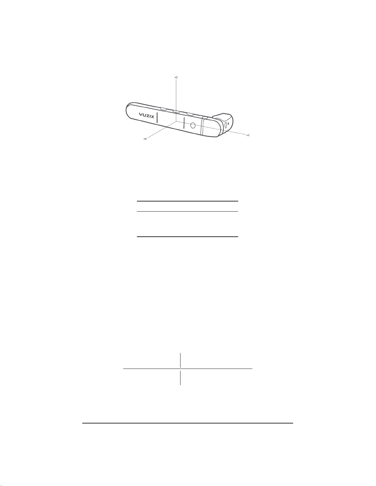
2.2.7 Orientation Sensor
M400C has an integrated orientation sensor with separate accelerometer, gyro, magnetometer
functions. Each function reports (X, Y, Z)values. The sensor also reports the device orienta-
tion using quaternion components (W, X, Y, Z). The sensor readings are reported to the host
over the USB Sensor HID class. For details see Section D.3.
The orientation of the X-, Y-, and Z-axes relative to the M400C device is shown in Figure 2.1.
7 Revision 7 Vuzix Corporation