Wärme BR-005 User manual

INSTALLATION AND OPERATING INSTRUCTIONS
Buffer tank
•BR-005
•BR-01
•BR-02
•BR-025
•BR-05

Str. 2

Str. 3
Table of contents
CONDITIONS FOR SAFE AND RELIABLE OPERATION............................................................................................. 4
DESTINY ................................................................................................................................................................ 5
Buffer dimensions 50 BR-005............................................................................................................................... 6
Construction buffer 100 BR-01............................................................................................................................. 8
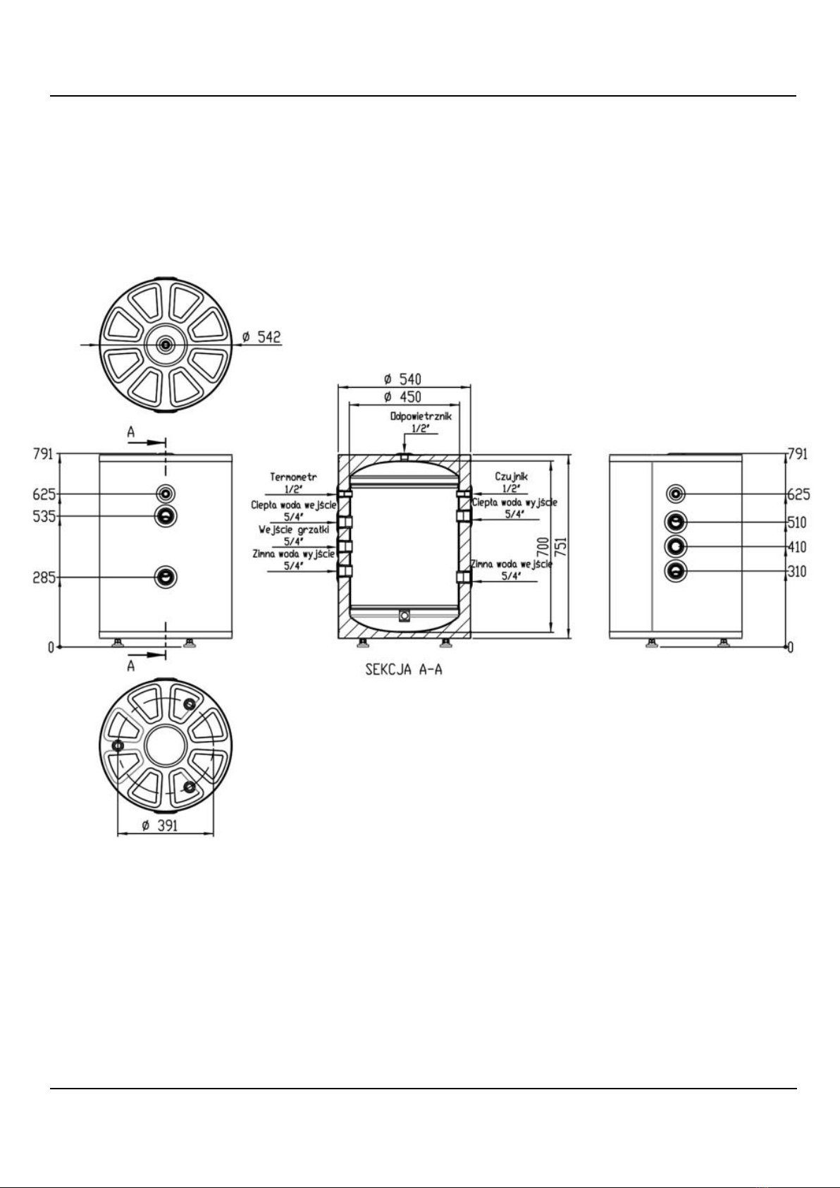
Buffer dimensions 100 BR-01............................................................................................................................... 9
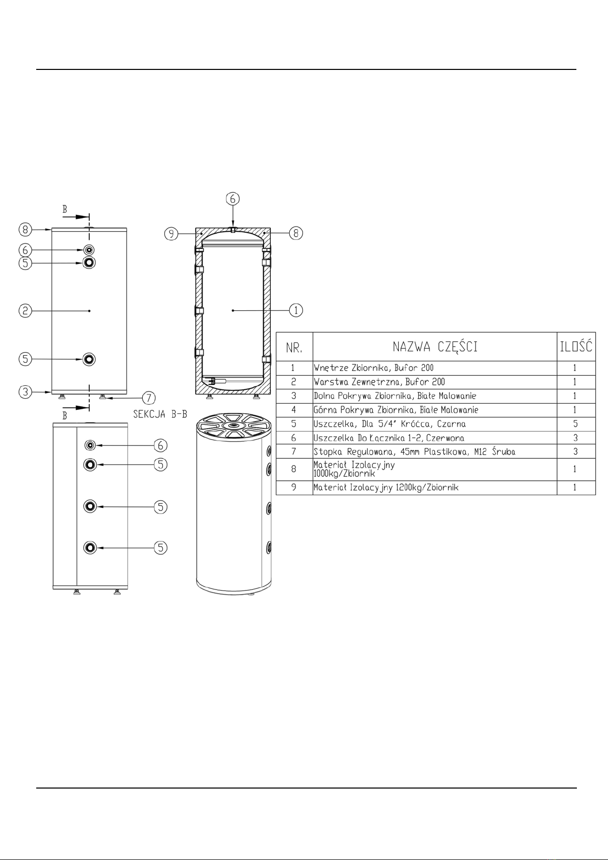
Buffer construction 200 BR-02........................................................................................................................... 10
Buffer dimensions 200 BR-02............................................................................................................................. 11
Construction of the BR-025 buffer ..................................................................................................................... 12
Buffer dimensions BR-025.................................................................................................................................. 13
Construction of the BR-05 buffer ....................................................................................................................... 14
Buffer dimensions BR-05.................................................................................................................................... 15
CONNECT............................................................................................................................................................ 16
RUN..................................................................................................................................................................... 16
TANK EMPTYING................................................................................................................................................. 16
OPERATION......................................................................................................................................................... 17
TECHNICAL SPECIFICATIONS............................................................................................................................... 17
WHAT TO DO IN CASE OF DAMAGE OR IRREGULARITIES
....................................................................................... 18
RECYCLING AND DISPOSAL OF WASTE
.................................................................................................................. 18
DECOMMISSIONING........................................................................................................................................... 18

Str. 4
CONDITIONS FOR SAFE AND RELIABLE OPERATION
1. Compliance with this installation and operation manual will enable proper
installation and operation of the device, ensuring a long service life and reliable
operation.
2. It is not allowed to install the buffer tank not in accordance with the instructions, it
threatens with failure, malfunction of the system and voids the warranty.
3. When working with the device, health and safety rules and other regulations in force
in a given country should be observed.
4. The device must not be installed in rooms where the ambient temperature may fall
below 0°C.
5. Installation and commissioning should be carried out by a specialist service facility.
6. The buffer tank shall be mounted vertically only.
7. The tank is a pressure device, the maximum working pressure of the tank is 0.4 MPa.
8. Heating water should meet the requirements of PN-C-04607:1991.
9. The maximum temperature of 95°C must not be exceeded in the operation of the
collectiontank.

Str. 5
DESTINY
Buffer tanks BR are devices designed for storing heating water in cooperation with
heating boilers and heat pumps. Appendixe application is the function of distributor,
hydraulic separator, heating circuit from the boiler room.
An electric heater can be mounted to the tank.

Str. 6
Buffer dimensions 50 BR-005

Str. 7

Str. 8
Construction buffer 100 BR-01

Str. 9
Buffer dimensions 100 BR-01

Str. 10
Buffer construction 200 BR-02

Str. 11
Buffer dimensions 200 BR-02

Str. 12
Construction of the BR-025 buffer

Str. 13
Buffer dimensions BR-025

Str. 14
Construction of the BR-05 buffer

Str. 15
Buffer dimensions BR-05

Str. 16
CONNECT
The buffer tank should only be installed in a standing position.
The buffer tank can be installed in the central heating system:
•Open system, made in accordance with PB-B-02413:1991,
•Closed system, made in accordance with PB-B-02414:1999.
RUN
Before starting the buffer tank, it is necessary to visually check the correctness of the
device connection.
Check the tightness of the connections.
Check the operation of the safety valve (according to the valve manufacturer's
instructions).
TANK EMPTYING
In order to empty the tank of water, it is necessary to:
•close the valves connecting the exchanger to the heating circuit,
•close the valve on the cold water supply to the exchanger,
•Open the drain valve.

Str. 17
OPERATION
Tanks are safe and reliable provided that the following rules are observed:
•do not operate the tank without a working safety valve,
•the operation of the valve should be checked every 14 days by turning the cap
so that there is a slight discharge of water,
•it is recommended to thermally insulate the discharge pipe and the coil
connection pipes to reduce heat loss,
•Any irregularities in the operation of the device should be reported to the
service facility.
These activities are at your own expense and are not subject to warranty.
TECHNICAL SPECIFICATIONS
Tank buforowy
BR-005
BR-01
BR-02
BR-025
BR-05
Rated capacity
l
50
100
170
245
454
Energy
efficiency
A
A
B
B
B
Rated
pressure
Mpa
0,4
Rated temperature
°C
95
Net weight
Kg
35
50
60
70
90

Str. 18
WHAT TO DO IN CASE OF DAMAGE OR IRREGULARITIES
RECYCLING AND DISPOSAL OF WASTE
Product and equipment disposal :
The product and equipment must not be disposed of with household waste.
Care must be taken to ensure that the product and all equipment are
disposed of correctly. All applicable laws must be observed.
DECOMMISSIONING
Used product cannot be treated as municipal waste. Proper disposal of the
used product prevents potential negative effects on the environment that
could occur in the event of improper waste management
. For more detailed
information on the recycling of this
product, please contact your local
government unit, waste management services.
Abnormality
Instructions for use
Tank water leakage
turn off the cold water supply valve and the shut-
off valves of the central heating system and
contact the service
Excessive pressure increase in the tank
Pressure increase in the central heating
system

Str. 19

Str. 20
PRODUCER
ENERGIA ON SP. Z O.O.
MIKOLAJA REJA 13/15/1101
81-874 SOPOT
WARME.COM.PL
This manual suits for next models
4
Table of contents
Other Wärme Electric Heater manuals
Popular Electric Heater manuals by other brands

Charnwood
Charnwood LA30iB Operating and installation instructions

EWT
EWT Leather LTH20LE instructions

Carrier
Carrier WEATHER MASTER P4 installation instructions

Dimplex
Dimplex Cheriton Fire CHT20 Installation and operating instructions

Goldair
Goldair GIR180 operating instructions

Bond
Bond HYUHI10000-1 owner's manual

Heylo
Heylo DE 9 XL user manual

Dyna-Glo
Dyna-Glo EG7500DH User's manual and operating instructions

Dimplex
Dimplex 430 RCE/B Installation and operating instructions

Harvia
Harvia KIP-30-W1 Owner's/operator's manual

Strend Pro
Strend Pro IFH02-50H instruction manual

Slant/Fin
Slant/Fin VICTORY II VHS Series Brochure & specs