Wärme ZC-02 User manual

INSTALLATION AND OPERATING INSTRUCTIONS
Tank 2in1
Models:
•ZC-02
•ZC-0 25
•ZCC-025
•ZC-05
•ZCC-05
•ZC-10

Str. 2
INS_14092022

Str. 3
INS_14092022
Table of contents
CONDITIONS FOR SAFE AND RELIABLE OPERATION............................................................................................. 4
CHARACTERISTICS OF PRESSURE EQUIPMENT..................................................................................................... 5
Tank construction 200 ZC-02................................................................................................................................ 6
Tank dimensions 200 ZC-02.................................................................................................................................. 7
Construction TankA 250 ZC-025........................................................................................................................... 8
Tank dimensions 250 ZC-025................................................................................................................................ 9
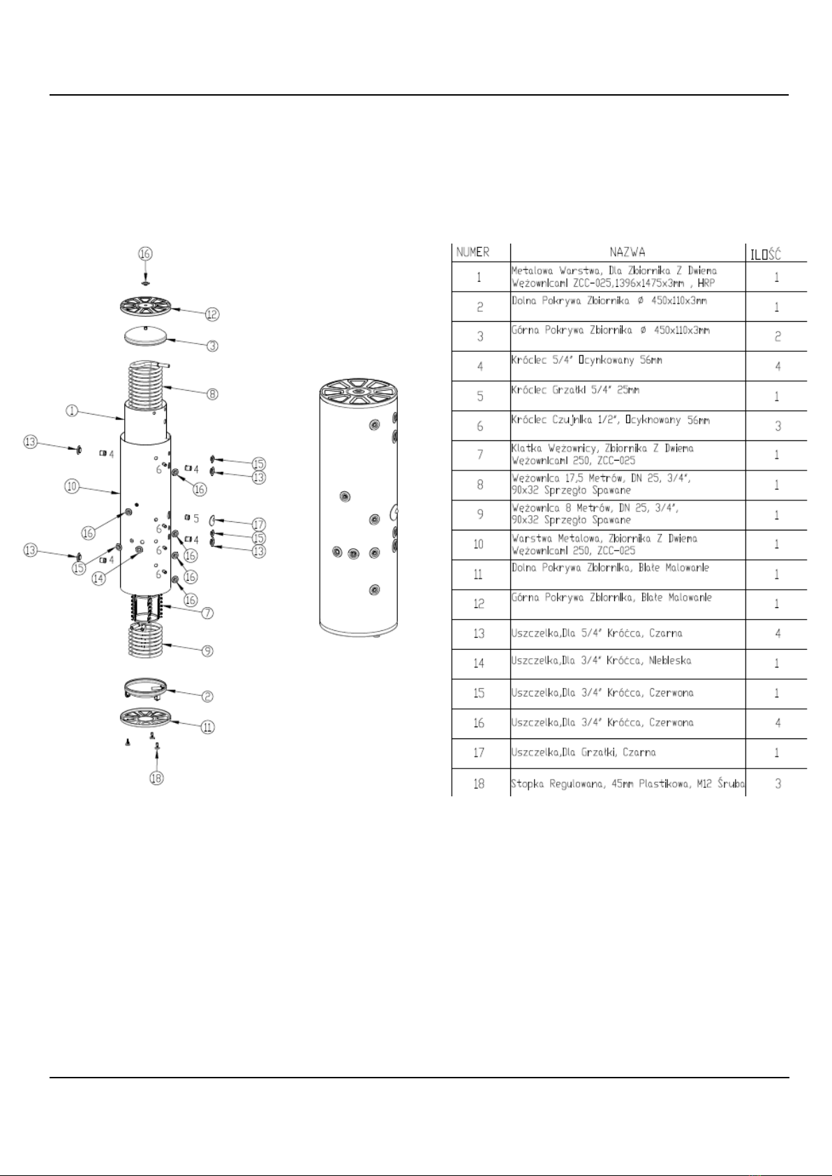
Construction of tank 250 with two coils ZCC-0 25 ............................................................................................. 10
Tank dimensions 250 with two coils ZCC-025 .................................................................................................... 11
Tank construction 500 ZC-05.............................................................................................................................. 12
Tank dimensions 500 ZC-05................................................................................................................................ 13
Tank dimensions 500 with two coils ZCC-05 ...................................................................................................... 14
Construction of Tank 500 with two coils ZCC-05................................................................................................ 15
Dimensions and construction of the tank 1000 ZC-10....................................................................................... 16
CONNECTION TO THE PLUMBING SYSTEM ........................................................................................................ 17
CONNECTION TO CENTRAL HEATING AND PLUMBING...................................................................................... 18
RUN..................................................................................................................................................................... 19
TANK EMPTYING................................................................................................................................................. 19
OPERATION......................................................................................................................................................... 20
TECHNICAL SPECIFICATIONS............................................................................................................................... 20
WHAT TO DO IN CASE OF DAMAGE OR IRREGULARITIES
....................................................................................... 21
RECYCLING AND DISPOSAL OF WASTE
.................................................................................................................. 21
DECOMMISSIONING........................................................................................................................................... 21

Str. 4
INS_14092022
CONDITIONS FOR SAFE AND RELIABLE OPERATION
1. Compliance with this installation and operation manual will enable proper
installation and operation of the device, ensuring a long service life and reliable
operation.
2. It is not allowed to install the tank not in accordance with the instructions, it
threatens with failure, malfunction of the system and causes the loss of warranty.
3. When working with the device, health and safety rules and other regulations in force
in a given country should be observed.
4. The device must not be installed in rooms where the ambient temperature may fall
below 0°C.
5. Installation and commissioning should be carried out by a specialist service facility.
6. The tank should only be mounted vertically.
7. After setting, the device must be connected to the water supply network and central
heating system according to the scheme contained in this manual.
8. The connection to the plumbing system should be made in accordance with PN-76/B-
02440.
9. The tank is a pressure device adapted to be connected to the plumbing, the
maximum pressure of the tank is 0.6 MPa and the rated pressure of the coil is 0.6 MPa. In case of
higher pressure in the plumbing, a pressure reducer should be installed.
10. Dripping water from the drainage pipe from the safety valve is normal and should
not be prevented, as a blockage of the valve can cause failure.
11. Do not use the tankif there is a chance that the safety valve is damaged.
12. The maximum temperature of 95°C must not be exceeded in the operation of the
collectiontank.
13. An additional diaphragm vessel selected according to the previously made
calculations should be installed to the tank.
14. An electric heater can be mounted to the tank.

Str. 5
INS_14092022
CHARACTERISTICS OF PRESSURE EQUIPMENT
A domestic hot water heating tank is a device designed for storing hot water for use
for central heating and domestic hot water by heating water contained in a large
surface coil. Due to the use of a flow coil (stainless steel AISI 316L) in the tank, there is
no need to use an anode and it is not necessary to periodically heat the tank because
there is a constant supply of fresh water.
The devices are additionally insulated by the use of thermal insulation in the form of
polyurethane foam.
ZC models are equipped with one coil, and ZCC models have two coils, which allows
you to connect, for example, a heat pump and a solar installation.

Str. 6
INS_14092022
Tank construction 200 ZC-02

Str. 7
INS_14092022
Tank dimensions 200 ZC-02

Str. 8
INS_14092022
Construction TankA 250 ZC-025

Str. 9
INS_14092022
Tank dimensions 250 ZC-025

Str. 10
INS_14092022
Construction of tank 250 with two coils ZCC-0 25

Str. 11
INS_14092022
Tank dimensions 250 with two coils ZCC-025

Str. 12
INS_14092022
Tank construction 500 ZC-05

Str. 13
INS_14092022
Tank dimensions 500 ZC-05

Str. 14
INS_14092022
Tank dimensions 500 with two coils ZCC-05

Str. 15
INS_14092022
Construction of Tank 500 with two coils ZCC-05

Str. 16
INS_14092022
Dimensions and construction of the tank 1000 ZC-10

Str. 17
INS_14092022
CONNECTION TO THE PLUMBING SYSTEM
The connection to the plumbing system should be made in accordance with PN-76/B-02440.
The tank is a pressure device adapted to connect to the water supply system, the maximum pressure of the
tank is 0.6 MPa, and the maximum pressure of the coil is 0.6 MPa, if the pressure in the water supply system
exceeds this value, a pressure reducer should be installed before the tank.
The tank must be connected to the water supply network as follows:
•A non-return valve should be installed on the water supply side to avoid the flow of water from the
tank side
•to the cold water supply port, install a tee with a safety group including a diaphragm vessel and a
safety valve with an opening pressure of 6 bar; there must be no shut-off valve or throttling
element between the tank and the safety valve and at its outlet, the safety valve must be mounted
in such a way that water leakage is visible,
•connect the exchanger with the installed safety valve to the water supply system,
•On the supply of cold water install a shut-off valve.
The domestic hot water outlet should be connected to the connector, which is located on the upper part of
the exchanger.
Circulation should be plugged in according to the scheme.
Suggestedconnection chemat:

Str. 18
INS_14092022
CONNECTION TO CENTRAL HEATING AND PLUMBING
The connection should be made as in the case of connection to the plumbing system
and additionally make:
•The connection to the central heating system should be made using 5/4"
connection screws and shut-off valves should be placed behind the screws.
Example connection diagram:

Str. 19
INS_14092022
RUN
Before starting the tank, it is necessary to check the correctness of the connection of
the device and the correctness of assembly according to the schemes.
The tank must be filled with water:
•Open the valve on the cold water supply,
•Open the hot water intake valve in the system (the outflow of a full stream of
water without air bubbles indicates that the tank is full),
•Close the tap valves.
TANK EMPTYING
In order to empty the tank of water, it is necessary to:
•close the valves connecting the exchanger to the heating circuit,
•close the valve on the cold water supply to the exchanger,
•Open the drain valve.

Str. 20
INS_14092022
OPERATION
Tanks are safe and reliable provided that the following rules are observed:
•do not operate the tank without a working safety valve,
•the operation of the valve should be checked every 14 days by turning the cap
so that there is a slight discharge of water,
•it is recommended to thermally insulate the discharge pipe and the coil
connection pipes to reduce heat loss,
•Any irregularities in the operation of the device should be reported to the
service facility.
These activities are at your own expense and are not subject to warranty.
TECHNICAL SPECIFICATIONS
Domestic
hot water tank
ZC-02
ZC-0 25
ZCC-
025
ZC-05
ZCC-05
ZC-10
Rated capacity
l
170
245
245
454
454
970
Energy efficiency
B
B
C
B
C
B
Maximum
pressure
tank
Mp
a
0.6
coil
0.6
Rated temperature
°C
90
Coil surface (top)
m2
3.83 m
5,48
4,81
8.76 m
Coil
surface
(bottom)
m2
X
X
1,75
X
1,75
X
Coil capacity
L
10,20
13,5
12,02
21,9
Coil capacity (bottom)
L
X
X
4,9
X
4,9
X
Net
weight
Kg
75
78
80
100
102
190
This manual suits for next models
5
Table of contents
Other Wärme Electric Heater manuals
Popular Electric Heater manuals by other brands

Dimplex
Dimplex Optiflame DF2608-LED instruction manual

Pentair
Pentair spa heater Operation and installation manual

Trotec
Trotec TEH 20 T Original instructions

MaxxGarden
MaxxGarden 21024 instruction manual

Fostoria
Fostoria SUN-MITE FES-1024-1CA Operation, installation, maintenance and parts manual

Thermofilm
Thermofilm HEATSTRIP THN2000 product manual