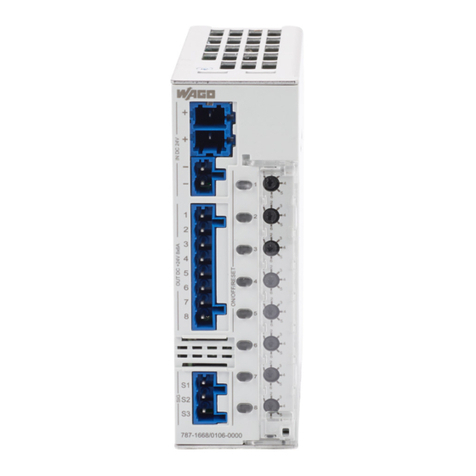
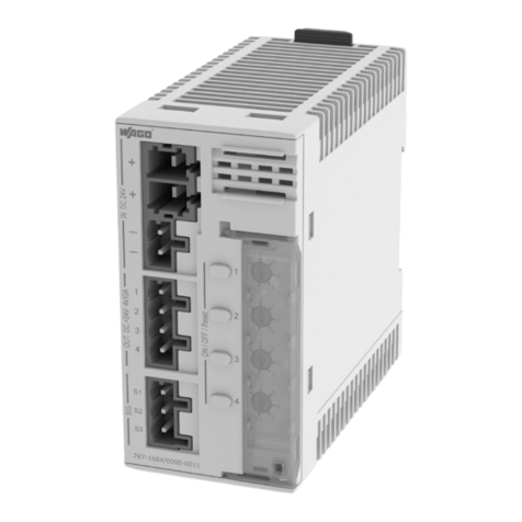
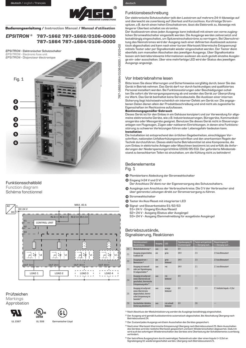
WAGO 787-2861 Series User manual

Pos: 2/ D oku me ntati on allg em ein /Ei nb and /Ei nb and Fro nts eite -H andb uch; CI 20 17; mit Do cVaria blen (St andar d) @ 28\mod_1486477502910_0.docx@ 405388@ @ 1
Manual
787-2861(/xxxx-xxxx)
Electronic Circuit Breaker
24 VDC, 0.5 ... 8 A
Version 1.3.1
Pos: 3/ A ll e S er ie n ( All g em ei ne M od ul e) /Rec htl ic h es, Allg e mei n es/ I mpr e ssu m für St a nd ard h an d büc h er - al lg . A ng a be n, Ansc hr i ft en, Telef onn u m mer n und E-M ail-A dr es s e n @ 3\mod_1219151118203_21.docx @ 21060 @ @ 1

2
787-2861 Electronic Circuit Breaker
Manual
Version 1.3.1
© 2019 WAGO Kontakttechnik GmbH & Co. KG
All rights reserved.
WAGO Kontakttechnik GmbH & Co. KG
Hansastraße 27
D-32423 Minden
Phone: +49 (0) 571/8 87 – 0
Fax: +49 (0) 571/8 87 – 1 69
E-Mail: [email protected]
Web: www.wago.com
Technical Support
Phone: +49 (0) 571/8 87 – 4 45 55
Fax: +49 (0) 571/8 87 – 84 45 55
E-Mail: [email protected]
Every conceivable measure has been taken to ensure the accuracy and
completeness of this documentation. However, as errors can never be fully
excluded, we always appreciate any information or suggestions for improving the
documentation.
E-Mail: [email protected]
We wish to point out that the software and hardware terms as well as the
trademarks of companies used and/or mentioned in the present manual are
generally protected by trademark or patent.
WAGO is a registered trademark of WAGO Verwaltungsgesellschaft mbH.
=== Ende d er List e f ür T e xt mar ke Ei nb a nd_ v orn e == =

Table of Contents 3
787-2861 Electronic Circuit Breaker
Manual
Version 1.3.1
Pos: 5/ D ok ume nt ati on allg em ein /V erz eic h nis se /I nhal ts ver z eic hni s - Ü b ers chri f t oG und V erz ei ch nis @ 3\mod_1219151230875_21.docx@21063 @ @ 1
Table of Contents
1Notes about this Documentation .............................................................5
1.1 Validity of this Documentation.................................................................5
1.2 Copyright................................................................................................5
1.3 Symbols .................................................................................................7
1.4 Number Notation ....................................................................................9
1.5 Font Conventions ...................................................................................9
2Important Notes ......................................................................................10
2.1 Legal Bases..........................................................................................10
2.1.1 Subject to Changes..........................................................................10
2.1.2 Personnel Qualifications ..................................................................10
2.1.3 Use of the 787 Series in Compliance with Underlying Provisions.....10
2.1.4 Technical Condition of Specified Devices.........................................11
2.2 Safety Advice (Precautions) .................................................................12
3Device Description..................................................................................15
3.1 View .....................................................................................................17
3.2 Connectors...........................................................................................18
3.3 Display Elements..................................................................................19
3.4 Operating Elements..............................................................................20
3.5 Technical Data .....................................................................................21
3.6 Approvals .............................................................................................24
3.7 Standards and Guidelines ....................................................................25
4Function Description ..............................................................................26
4.1 Tripping Characteristics........................................................................26
4.2 Undervoltage and Overvoltage Detection .............................................28
4.3 Activating Capacitive Loads..................................................................29
4.4 ON delay ..............................................................................................29
4.5 Control Input S1....................................................................................30
4.6 Signal Output S2 ..................................................................................31
5Mounting..................................................................................................33
5.1 DIN-35 Rail...........................................................................................33
5.1.1 Mounting on DIN-Rail.......................................................................33
5.1.2 Removal from the DIN-Rail ..............................................................34
6Connect Devices .....................................................................................35
6.1 Connection Example ............................................................................35
6.1.1 Connection Example 787-2861/0xx0-0000.......................................35
6.1.2 Connection Example 787-2861/0108-0020 ......................................36
6.2 Distribute Potential ...............................................................................38
6.3 Bridging Voltage or Signal ....................................................................39
7Configuration (787-2861/0108-0020 only) ..............................................40
8Diagnostics..............................................................................................41
8.1 General Operating Statuses .................................................................41
List of Figures ..................................................................................................44

Notes about this Documentation 5
787-2861 Electronic Circuit Breaker
Manual
Version 1.3.1
Pos: 7/ Al le Seri e n (A llg e mei n e M od ul e) /Üb ers c hri ft en/ Ebe n e 1/H in wei s e z u dies er D o ku ment ati on - Ü ber sc hr ift 1 @ 4\mod_1237987661750_21.docx @ 29029@ 1@ 1
1 Notes about this Documentation
Pos: 8/ All e S eri en (A llg em eine M od ul e)/Si cher h eits- und sonstige Hinweise/Hinweis/Hinweis:Do kumentationauf be w ahr e n @ 4\mod_1237987339812_21.docx @ 29026@ @ 1
Always retain this documentation!
This documentation is part of the product. Therefore, retain the documentation
during the entire service life of the product. Pass on the documentation to any
subsequent user. In addition, ensure that any supplement to this documentation
is included, if necessary.
Pos: 9/ All e S eri en (A llg em eine M od ul e)/Üb ers chr ift en/E ben e 2/ Gül tig kei tsber eic h - Üb ers c hri ft 2 @ 12\mod_1338912448776_21.docx@ 96469@ 2 @ 1
1.1 Validity of this Documentation
Pos: 10 /S eri e 7 87 ( EPS IT RON )/H i nw eise zur D o ku ment ati on/ Gül tig kei ts ber eic h/ Gül tig kei t D ok ume nt ati on E l ektr onis c her S ch utzs c hal ter 787-16xx/2861@ 13\mod_1342442188427_21.docx@ 100350@ @ 1
This documentation applies to the electronic circuit breaker 787-2861 and the
versions listed in the following table.
Pos: 11 /S er i e 7 8 7 ( E PS IT RON ) /Hi n wei se zur D o ku ment at i on /V ar ia nt enli s te n/ Var i an te nl is t e El e ktr o nis ch er Schut z sc hal t er 787-2861/787-2861/0108-002 0 @ 23\mod_1436271316353_21.docx@ 185476@ @ 1
Table 1: Versions
Item No./Version
Description
787-2861/0050-0000
Electronic Circuit Breaker,
24 VDC, 0.5 A
787-2861/0100-0000
Electronic Circuit Breaker,
24 VDC, 1 A
787-2861/0200-0000
Electronic Circuit Breaker,
24 VDC, 2 A
787-2861/0400-0000
Electronic Circuit Breaker,
24 VDC, 4 A
787-2861/0600-0000
Electronic Circuit Breaker,
24 VDC, 6 A
787-2861/0800-0000
Electronic Circuit Breaker,
24 VDC, 8 A
787-2861/0108-0020
Electronic Circuit Breaker, adjustable
24 VDC, 1 … 8 A
Pos: 12 /Al l e S eri en ( All ge mei ne M od ule) / Sich er heit s- und sons ti ge H i n weis e/Hi n weis /H in wei s: Gülti g keit der Anga ben für a ufg el iste te Vari a nten @ 9\mod_1281520778141_21.docx@ 63085@ @ 1
Documentation Validity for Variants
Unless otherwise indicated, the information given in this documentation applies
to listed variants.
Pos: 13.1 / All e Seri en ( All ge mei ne M od ule) /Ü bers chr ift e n/ Ebe ne 2/U r heb er sc hutz -Ü ber sc hri ft 2 @ 23\mod_1435647042188_21.d ocx @ 18480 8 @ 2@ 1
1.2 Copyright
Pos: 13.2 / All e Seri en ( A llg e mei ne M o dul e)/R ec htl ich es , Al lg e mei nes /U rh eb ers c hutz aus führ li ch @ 4\mod_1235565145234_21.docx@ 27691@ @ 1
This Manual, including all figures and illustrations, is copyright-protected. Any
further use of this Manual by third parties that violate pertinent copyright
provisions is prohibited. Reproduction, translation, electronic and phototechnical
filing/archiving (e.g., photocopying) as well as any amendments require the
written consent of WAGO Kontakttechnik GmbH & Co. KG, Minden, Germany.
Non-observance will involve the right to assert damage claims.

6 Notes about this Documentation
787-2861 Electronic Circuit Breaker
Manual
Version 1.3.1
Pos:13.3/Dokumentationallgemein/Gliederungselemente/---Seit e n wec hs el--- @ 3\mod_1221108045078_0.docx@ 21810@ @ 1

Notes about this Documentation 7
787-2861 Electronic Circuit Breaker
Manual
Version 1.3.1
Pos: 13.4 / All e Seri en ( All ge mei ne M od ule) /Ü bers chr ift e n/ Ebe ne 2/ S ymbol e - Ü b ers chr if t 2@ 13\mod_1351068042408_21.docx@ 105270@ 2 @ 1
1.3 Symbols
Pos: 13 .5.1 /Al le Seri en (All gemei ne Mod ule)/ Sicher heits- u nd sons ti g e H i n weis e/ Ge fa hr/ G ef ahr : _War nu ng vor P ers on ens ch ä de n al lgemein_- Erläu ter ung @ 13 \mod_1343309450020_21.docx@ 101029@ @ 1
Personal Injury!
Indicates a high-risk, imminently hazardous situation which, if not avoided, will
result in death or serious injury.
Pos: 13 .5.2 /Al le Seri en (All gemei ne Mod ul e)/ Si ch er h eits - u nd so ns ti ge H i n weis e/ Ge fahr /G ef ahr : _War nung vor Pers on en sch ä den durc h el e ktri sc he n Str o m_ - Erläuterung@ 13\mod_1343309694914_21.docx@ 101030@ @ 1
Personal Injury Caused by Electric Current!
Indicates a high-risk, imminently hazardous situation which, if not avoided, will
result in death or serious injury.
Pos: 13 .5.3 /Al le Seri en (All gemei ne Mod ule)/ Sicher heits- u nd sons ti ge H i nwei s e/W ar nung / War n ung: _W arn u ng vor P er so nens c häd e n al lg emei n_ - Erläuterung@ 13\mod_ 1343309877041_21.docx@ 101035@ @ 1
Personal Injury!
Indicates a moderate-risk, potentially hazardous situation which, if not avoided,
could result in death or serious injury.
Pos: 13 .5.4 /Al le Seri en (All gemei ne Mod ule)/ Sicher heits- und sonstigeHi nweis e/ Vor si c ht /Vor si ch t: _War nung vor Pers on ens c häd en allg em ein _ - Erläuterung @ 13\mod_1343310028762_21.docx@ 101038@ @ 1
Personal Injury!
Indicates a low-risk, potentially hazardous situation which, if not avoided, may
result in minor or moderate injury.
Pos: 13 .5.5 /Al le Seri en (All gemei ne Mod ule)/ Sicher heits- u nd sons ti ge H i nwei s e/A c htung / Ach tu ng : _ War nu ng vor Sachsc h äd en al lg em ein _ - Erläuterung@ 13\mod_1343310134623_21.docx @ 101041@ @ 1
Damage to Property!
Indicates a potentially hazardous situation which, if not avoided, may result in
damage to property.
Pos: 13 .5.6 /Al le Seri en (All gemei ne Mod ule)/ Sicher heits- u nd sons ti ge H i nwei s e/A c htung / Ach tu ng : _ War nu ng vor Sachsc h äd en d urc h elek tros tat is ch e Aufla du ng_ - Erl äut er ung @ 13\mod_1343310227702_21.docx @ 101044@ @ 1
Damage to Property Caused by Electrostatic Discharge (ESD)!
Indicates a potentially hazardous situation which, if not avoided, may result in
damage to property.
Pos: 13 .5.7 /Al le Seri en (All gemei ne Mod ul e)/ Si ch er h eits - und sonstige Hi nweise/Hinweis/Hinweis:_ WichtigerHi nweis allgemein_ - Erläuterung@ 13\mod_1343310326906_21.docx @ 101047@ @ 1
Important Note!
Indicates a potential malfunction which, if not avoided, however, will not result in
damage to property.
Pos: 13 .5.8 /Al le Seri en (All gemei ne Mod ule)/ Sicher heits- u nd sons ti g e H i n weis e/I nf or ma ti o n/I nf or ma ti on: _W eiter e I nf or ma ti on allg e mei n_ -Er l äu ter ung @ 13 \mod_1343310439814_21.docx@ 101051@ @ 1

8 Notes about this Documentation
787-2861 Electronic Circuit Breaker
Manual
Version 1.3.1
Additional Information:
Refers to additional information which is not an integral part of this
documentation (e.g., the Internet).
Pos:13.6/Dokumentationallgemein/Gliederungselemente/---Seit e n wec hs el--- @ 3\mod_1221108045078_0.docx@ 21810@ @ 1

Notes about this Documentation 9
787-2861 Electronic Circuit Breaker
Manual
Version 1.3.1
Pos: 13.7 / All e Seri en ( Al lg e mei ne Mod ule) /Ü ber s c hri ft e n/ Eb e ne 2/D ar st ell u ng der Z a hle ns ys te m e - Ü ber s chr if t 2 @ 2 3\mod_1435647128078_21.docx@ 184811@ 2@ 1
1.4 Number Notation
Pos: 13.8 / All e Seri en ( A llg e mei ne M o dul e)/R ec htl ich es , Al lg e mei nes /Z ahl e ns yst e me @ 3\mod_1221059454015_21.docx @ 21711 @ @ 1
Table 2: Number Notation
Number Code
Example
Note
Decimal
100
Normal notation
Hexadecimal
0x64
C notation
Binary
'100'
'0110.0100'
In quotation marks, nibble separated
with dots (.)
Pos: 13.9 / All e Seri en ( All ge mei ne M od ule) /Ü bers chr ift e n/ Ebe ne 2/ Sc hri ft ko nvent i one n - Ü ber sc hri ft 2 @ 23\mod_1435647186005_21.docx @ 184814@ 2@ 1
1.5 Font Conventions
Pos: 13.1 0 / Al le Ser ie n (Al l ge m ein e M o dul e)/ Re ch tl ic h es, Allg e mei n es/ Sc hr if t kon ve nti on en @ 3\mod_1221059521437_21.docx@ 21714@ @ 1
Table 3: Font Conventions
Font Type
Indicates
italic
Names of paths and data files are marked in italic-type.
e.g.: C:\Program Files\WAGO Software
Menu
Menu items are marked in bold letters.
e.g.: Save
>
A greater-than sign between two names means the selection of a
menu item from a menu.
e.g.:
File
>
New
Input
Designation of input or optional fields are marked in bold letters,
e.g.:
Start of measurement range
“Value”
Input or selective values are marked in inverted commas.
e.g.: Enter the value “4 mA” under Start of measurement range.
[Button]
Pushbuttons in dialog boxes are marked with bold letters in square
brackets.
e.g.: [Input]
[Key]
Keys are marked with bold letters in square brackets.
e.g.:
[F5]
Pos: 14 /D o kum e nt atio n allg emei n/ Gl ie der ung s el e me nte /---Sei t e n wec hs el--- @ 3\mod_1221108045078_0.docx@ 21810@ @ 1

10 Important Notes
787-2861 Electronic Circuit Breaker
Manual
Version 1.3.1
Pos: 15 /Al l e S eri en ( All ge mei ne M od ule) /Ü b ersc hrif te n/ Ebe ne 1/ Wic hti ge Erl äu ter unge n - Ü ber sc hr ift 1 @ 4 \mod_1241428899156_21.docx@32170 @ 1 @ 1
2 Important Notes
Pos: 16.1 / All e Seri en ( All ge mei ne M od ule) /R ec htli ch es, Al lg em ei nes /Wi chti g e Er l äuter ung en - Einl eit u ng @ 3\mod_1221059818031_21.docx@ 21717@ @ 1
This section includes an overall summary of the most important safety
requirements and notes that are mentioned in each individual section. To protect
your health and prevent damage to devices as well, it is imperative to read and
carefully follow the safety guidelines.
Pos: 16 .2 /All e Seri en( Allg emeine M odul e)/Ü berschr ifte n/Ebe ne 2/Rec htlic he Gr undlag en - Über sc hr ift 2 @ 3\mod_1221060626343_21.docx@ 21726@ 2 @ 1
2.1 Legal Bases
Pos: 16.3 / All e Seri en ( A llg e mei ne M o dul e)/R ec htl ich es , Al lg e mei nes /Ä nd er ung s vor beh alt - Üb ersc hrift 3 un d Inhal t @ 3\mod_1221060036484_21.docx@ 21720 @ 3 @ 1
2.1.1 Subject to Changes
WAGO Kontakttechnik GmbH & Co. KG reserves the right to provide for any
alterations or modifications. WAGO Kontakttechnik GmbH & Co. KG owns all
rights arising from the granting of patents or from the legal protection of utility
patents. Third-party products are always mentioned without any reference to
patent rights. Thus, the existence of such rights cannot be excluded.
Pos:16.4/Serie787(EPSITRON)/WichtigeErlä ut er ung e n/ Per s o nalq u al ifi kati on 787-xxxx @ 11\mod_1317113061338_21.docx@ 79692@ 3 @ 1
2.1.2 Personnel Qualifications
All sequences implemented on 787 Series devices may only be carried out by
electrical specialists with sufficient knowledge in automation. The specialists must
be familiar with the current norms and guidelines for the devices and automated
environments.
Pos:16.5/Serie787(EPSITRON)/WichtigeErläuterungen/Bestimmungsgemäße Verwendung 0787-xxxx@ 11\mod_1317113060572_21.docx@ 79688@ 3@ 1
2.1.3 Use of the 787 Series in Compliance with Underlying
Provisions
The 787 Series power supply system provides DC voltage to electric or electronic
devices, such as industrial control systems or display, communication and
measuring devices.
The devices have been developed for use in an environment that meets the IP20
protection class criteria. Protection against finger injury and solid impurities up to
12.5 mm diameter is assured; protection against water damage is not ensured.
Unless otherwise specified, operation of the components in wet or dusty
environments is prohibited.
The devices are designed for installation in an enclosure. Under no
circumstances may they be used in control systems for planes or in nuclear
facilities, as any malfunction in these applications could result in severe injuries
or risk of death.
Pos:16.6/Dokumentationallgemein/Gliederungselemente/---Seit e n wec hs el--- @ 3\mod_1221108045078_0.docx@ 21810@ @ 1

Important Notes 11
787-2861 Electronic Circuit Breaker
Manual
Version 1.3.1
Pos: 16.7 / All e Seri en ( A llg e mei ne M o dul e)/R ec htl ich es , Al lg e mei nes /T ec hni sc her Zus ta nd d er Ger ät e - Ü bersc hrift 3 u nd Inhal t @ 3\mod_1221060446109_21.docx@ 21723@ 3 @ 1
2.1.4 Technical Condition of Specified Devices
The devices to be supplied ex works are equipped with hardware and software
configurations, which meet the individual application requirements. These
modules contain no parts that can be serviced or repaired by the user. The
following actions will result in the exclusion of liability on the part of WAGO
Kontakttechnik GmbH & Co. KG:
• Repairs,
• Changes to the hardware or software that are not described in the
operating instructions,
• Improper use of the components.
Further details are given in the contractual agreements. Please send your
request for modified and new hardware or software configurations directly to
WAGO Kontakttechnik GmbH & Co. KG.
Pos:16.8/Dokumentationallgemein/Gliederungselemente/---Seit e n wec hs el--- @ 3\mod_1221108045078_0.docx@ 21810 @ @ 1

12 Important Notes
787-2861 Electronic Circuit Breaker
Manual
Version 1.3.1
Pos: 16.9 / All e Seri en ( All ge mei ne M od ule) /Ü bers chr ift e n/ Ebe ne 2/ Sic her hei t shi nwei se - Ü ber sc hr ift 2 @ 6\mod_1260180299987_21.docx@ 46724 @ 2@ 1
2.2 Safety Advice (Precautions)
Pos: 16.1 0 /Al le S eri en ( Allg em ein e Mo dul e)/Si ch erh eits- un d sonst ige Hi nweis e/Einl eitu ng Sich erhei tshin weise Har dwar e @ 6\mod_1260180170493_21.docx @ 46720@ @ 1
For installing and operating purposes of the relevant device to your system the
following safety precautions shall be observed:
Pos: 16.1 1 /Al le S eri en ( Allg em ein e Mo dul e)/Si ch erh eits- un d sonst ig e Hinw eis e/G ef a hr/ G ef ahr: Nich t an G er ät e n unter Spann u ng arbei t en! @ 6\mod_1260180365327_21.docx@ 46727@ @ 1
Do not work on devices while energized!
All power sources to the device shall be switched off prior to performing any
installation, repair or maintenance work.
Pos: 16.1 2 /Al le S eri en ( Allg em ein e Mo dul e)/Si ch erh eits- un d sonst ig e Hinw eis e/G ef a hr/ G ef ahr: Ber ühr b are spa nn u ngs f ühr en de Teil e! @ 1 5\mod_1366793178366_21.docx@117864@ @1
Live parts are likely to be touched!
The party setting up the device is responsible for providing appropriate touch
guards. The installation regulations must be observed for each individual
application.
Pos: 16.1 3 / S eri e 787 ( EP SITR ON )/ Wich t ig e Erlä ut eru ng e n/Si c h erh ei ts- un d sonsti g e H in w eis e/G ef a hr/ G ef ahr: Einb a u 787-xxxx nur i n G e häus en , Sc hr änke n oder elektr is che n B etri ebs r äum en! @ 11 \mod_1317113246230_21.docx@79696 @ @ 1
Installation only in appropriate housings, cabinets or in electrical operation
rooms!
Always install devices of the 787 Series in enclosures, cabinets or electrical
equipment rooms which can be closed and locked. Ensure that access to this
equipment/these rooms is possible only by authorized specialists with the
appropriate key or tools.
Pos: 16.1 4 / S eri e 7 87 ( EP SITR ON )/ Wi ch ti g e Er lä ut er u ng en/ Sic h er h eits - un d s ons tig e Hin wei s e/G ef a hr /G ef ahr : G er ä te nicht in St eu er ung s anl ag e n v er we nd en! @ 13 \mod_1346400862576_21.docx@ 102180@ @ 1
Do not use these devices in control systems for planes, trains or nuclear
facilities!
Never use these devices in control systems for planes, trains or nuclear facilities,
as any malfunction in these applications can result in severe injuries or risk of
death!
Pos: 16.1 5 / Alle Ser ien ( Allg em ein e M odul e)/Si c herh eits - und sonsti g e H in w eis e/ G ef ahr /G ef ahr : Unfal l ver h üt u ngs vor sc hr i ft en b e ach te n! @ 6\mod_1260180657000_21.docx@ 46735@ @ 1
Pos: 16.1 6 /Al le S eri en ( Allg em ein e Mo dul e)/Si ch erh eits- un d sonst ig e Hinw eis e/G ef a hr/ G ef ahr: Auf nor mg erec ht e n Anschl uss acht en! @ 6 \mod_1260180753479_21.docx@ 46739 @ @ 1
Ensure a standard connection!
To minimize any hazardous situations resulting in personal injury or to avoid
failures in your system, the data and power supply lines shall be installed
according to standards, with careful attention given to ensuring the correct
terminal assignment. Always adhere to the EMC directives applicable to your
application.
Pos: 16.1 7 / S er ie 787 ( EP SIT R ON )/ Wi ch ti g e Er l äut er u ng en/ Sic h er h eits - und s o nsti g e H in w eis e/ A ch tu ng /A cht u ng : V ers or g ung ss p an n ung bei d ef e kte m Gerät absc hal t e n! @ 13\mod_1346401405605_21.docx @ 102187@ @ 1

Important Notes 13
787-2861 Electronic Circuit Breaker
Manual
Version 1.3.1
Switch off power supply to defective device!
Switch off power supply to the device immediately if the device malfunctions or is
damaged! Control systems connected to the device may also be damaged!
Return the defective device directly to WAGO.
Pos: 16.1 8 / S er ie 787 ( EP SIT R ON )/ Wi ch ti g e Er l äut er u ng en/ Sic h er h eits - und sonstigeHinweise/Achtung/Achtung:FreischwingendeLeiterendend urc h ein e ge eig net e Z ugen tlas tung ab fang en! (ohn e F eder leis te) @ 23 \mod_1435643960160_21.docx@ 184791@ @ 1
Use strain relief!
Electronic contacts can be damaged by high vibration levels or shock impacts!
Provide appropriate strain relief means to attach and cap any free ends of the
conductors.
Pos: 16.1 9 /Al le S eri en ( Allg em ein e Mo dul e)/Si ch erh eits- un d sonsti g e H in wei s e/V orsi c ht/ Vors ic ht : H ei ße Oberfl äc he nicht berü hr en! (all ge m ein) @ 6\mod_1264428115588_21.docx@48610 @ @ 1
Do not touch hot surfaces!
The surface of the housing can become hot during operation. If the device was
operated at high ambient temperatures, allow it to cool off before touching it.
Pos: 16.2 0 /Al le S eri en ( Allg em ein e Mo dul e)/Si ch erh eits- und sonstige Hinweise/Achtung/Achtung:G erätevor kriec hende n und isol iere nden S toffen s chütz en! @ 6\mod_1260181036216_21.docx @ 46747@ @ 1
Protect the components against materials having seeping and insulating
properties!
The components are not resistant to materials having seeping and insulating
properties such as: aerosols, silicones and triglycerides (found in some hand
creams). If you cannot exclude that such materials will appear in the component
environment, then install the components in an enclosure being resistant to the
above-mentioned materials. Clean tools and materials are imperative for
handling devices/modules.
Pos: 16.2 1 /Al le S eri en ( Allg em ein e Mo dul e)/Si ch erh eits- un d sonst ige Hi nweis e/Ach tung/ Achtu ng: Rei nigu ng nur mit z ulässi gen M aterial ien! @ 6\mod_1260181203293_21.docx@ 46751@ @ 1
Clean only with permitted materials!
Clean housing and soiled contacts with propanol.
Pos: 16.2 2 /Al le S eri en ( Allg em ein e Mo dul e)/Si ch erh eits- und sonstige Hinweise/Achtung/Achtung: KeinKontaktspray verwenden!@ 6\mod_1260181290808_21.docx @ 46755@ @ 1
Do not use any contact spray!
Do not use any contact spray. The spray may impair contact area functionality in
connection with contamination.
Pos: 16.2 3 /Al le S eri en ( Allg em ein e Mo dul e)/Si ch erh eits- un d sonst ige Hi nweis e/Ach tung/ Achtu ng: Ver polung en der D aten- u nd Versor gung sleit unge n vermei den! @ 6\mod_1260184045744_21.docx@ 46767@ @ 1

14 Important Notes
787-2861 Electronic Circuit Breaker
Manual
Version 1.3.1
Do not reverse the polarity of connection lines!
Avoid reverse polarity of data and power supply lines, as this may damage the
devices involved.
Pos: 16.2 4 /Al le S eri en ( Allg em ein e Mo dul e)/Si ch erh eits- un d sonsti g e H in wei s e/A ch tung /Ac ht u ng : El ektr os t atis c he Entla du ng verm ei den! - DIN EN 61340-5-1/-3 @ 6\mod_1260181364729_21.docx@ 46759@ @ 1
Avoid electrostatic discharge!
The devices are equipped with electronic components that may be destroyed by
electrostatic discharge when touched. Please observe the safety precautions
against electrostatic discharge per DIN EN 61340-5-1/-3. When handling the
devices, please ensure that environmental factors (personnel, work space and
packaging) are properly grounded.
Pos: 17 /D o kum e nt atio n allg emei n/ Gl ie der ung s el e me nte /---Sei t e n wec hs el--- @ 3\mod_1221108045078_0.docx@ 21810@ @ 1

Device Description 15
787-2861 Electronic Circuit Breaker
Manual
Version 1.3.1
Pos: 18 /A ll e Seri en (Allg e mei n e M od ul e)/ Ü b ers chr if te n/ Eb e ne 1/G erät e bes c hr ei bung - Üb er schr i f t 1@ 3\mod_1233756084656_21.docx@ 27096 @ 1@ 1
3 Device Description
Pos: 19.1 / S eri e 787 ( E PS ITR ON ) / Ger ät ebes c hr ei b ung / Bes chr eib ung /Anwendung/Anwendung 787-2861 @ 23\mod_1435323488284_21.docx@ 184666@ @ 1
The 787-2861/0xx0-0000 electronic circuit breaker reliably protects load circuits
against short circuiting and overloading. The 24 VDC input voltage can be
provided with fuse protection for the following current values:
Table 4: Output Fuse Protection
Version
Fuse Protection
Color Coding
787-2861/0050-0000
0.5 A
Green
787-2861/0100-0000
1 A
Brown
787-2861/0200-0000
2 A
Red
787-2861/0400-0000
4 A
Yellow
787-2861/0600-0000
6 A
Blue
787-2861/0800-0000
8 A
Gray
787-2861/0108-0020
1 A ... 8 A
-
The electronics can accommodate brief current peaks.
Pos:19.2/Serie787( E PS ITR ON )/ G er ät eb esc hr ei b ung / Bes c hr ei bung / L ED -A nzei g e/ L ED-A nz eig e 787-2861@ 23\mod_1436342089493_21.docx@ 185670@ @ 1
LEDs indicate the respective status of the output and current setting.
Pos: 19.3 / S eri e 787 ( E PS ITR ON ) / Ger ät ebes c hr ei b ung / Bes chr eib ung/Funktion/Funktion787-2861: K ur z sc hl u ss und Ü b er las t @ 2 3\mod_1436342179935_21.docx@ 185687@ @ 1
In the event of a short circuit or overloading, the individual channel is de-
energized after a defined trip time.
Pos:19.4/Serie787( E PS ITR ON )/ G er ät eb esc hr ei b ung / Bes c hr ei bung / A n we ndu ng /H in w eis e/ Hi n wei s: Ther mi sc he Ents pa n nu ng abwar t en 787-16xx@ 12\mod_1342431732847_21.docx @ 100298 @ @ 1
Wait for temperature to return to normal!
If a channel has been de-activated due to short-circuiting or overloading, wait
until the temperature returns to its normal range (cooling period) before re-
activating the channel.
Pos: 19.5 / S eri e 7 8 7 (E PS I TR ON) / Ger ät eb esc hr ei b ung / Bes chr ei bung / F un kti on /F u nk ti on 787-2861:Signalkontakte@ 23\mod_1435572867601_21.docx@ 184762@ @ 1
The device has a control input and a signal output.
• Control input: The channel can be switched ON and OFF from here.
• Signal output: The operating status can be read from here.
Pos:19.6/Serie787( E PS IT RO N) / Ger ät eb esc hr ei b ung/ Bes chr ei b ung/ A nwe n du ng /A n wen d ung 787-2861/0108-0020@ 28\mod_1484046480599_21.docx @ 402718 @ @ 1
The 787-2861/0108-0020 electronic circuit breaker variably protects load circuits
with current levels from 1 A … 8 A. The trip current and behavior of the signal
output can be configured using the push and slide switch. LEDs indicate the
respective status of the channel and current setting.
Pos:19.7/Dokumentationallgemein/Gliederungselemente/---Seit e n wec hs el--- @ 3\mod_1221108045078_0.docx@ 21810@ @ 1

16 Device Description
787-2861 Electronic Circuit Breaker
Manual
Version 1.3.1
Pos: 19.8 / S eri e 7 8 7 (E PS I TR ON) / Ger ät eb esc hr ei b ung / Bes chr ei bung / F un kti on /F u nk ti on 787-2 861 : B eg r i ffs de fi ni ti on e n @ 30\mod_1501165191261_21.docx @ 456661@ @ 1
The terms “switched ON” and “switched OFF”, as well as “tripped” are used in
this manual. To clearly delineate these terms, they are explained as follows:
Table 5: Definition of Terms
Designation
Definition
Switched ON
The user has activated the electronic circuit breaker
manually from the push and slide switch or via a
corresponding signal at the control input. The load
circuit is closed, the current flows.
Switched OFF
The user has deactivated the electronic circuit
breaker manually from the push and slide switch or
via a corresponding signal at the control input. The
load circuit is open, the current flow is interrupted.
Tripped
The electronics of the electronic circuit breaker has
been tripped due to overcurrent, undervoltage or
overvoltage. The load circuit is open, the current
flow is interrupted.
Pos: 20 /D o kum e nt atio n allg emei n/ Gl ie der ung s el e me nte /---Sei t e n wec hs el--- @ 3\mod_1221108045078_0.docx@ 21810@ @ 1

Device Description 17
787-2861 Electronic Circuit Breaker
Manual
Version 1.3.1
Pos: 21 /Al l e S eri en ( All ge mei ne M od ule) /Ü b ersc hrif te n/ Ebe ne 2/ A nsic ht - Ü b ers chr if t 2 @ 4 \mod_1240984217343_21.docx@ 31958@ 2 @ 1
3.1 View
Pos: 22 / S eri e 787 ( E PS ITR ON )/ Ger ät eb es c hr ei b ung / An s ic ht /A nsi c ht 787-2861@ 23\mod_1435588017099_21.docx@ 184765@ @ 1
Figure 1: View
Table 6: Legend for „View“ Figure
Position
Designation
(1)
Connections (see section “Connections”)
(2)
(3)
(4)
(5)
(6)
(7)
(8)
(a)
787-2861/0xx0-0000: Transparent cover with labeling area and color
coding stripes.
The LEDs (d) and (e) and the push and slide switch (see “Operating
Elements”) are located under the transparent cover.
787-2861/0108-0020: Transparent cover with labeling area.
The LEDs (d) and (e) and the push and slide switch (see “Operating
Elements”) are located under the transparent cover.
(b)
Technical data
(c)
Snap-in mounting foot
(d)
Status LED
(e)
Configuration LED
Pos: 23 /D o kum e nt atio n allg emei n/ Gl ie der ung s el e me nte /---Sei t e n wec hs el--- @ 3\mod_1221108045078_0.docx@ 21810@ @ 1

18 Device Description
787-2861 Electronic Circuit Breaker
Manual
Version 1.3.1
Pos: 24 /Al l e Ser i en ( All ge mei ne M o dul e)/Ü b ersc hri fte n/ Ebe ne 2/Ans c hlüss e - Ü ber sc hr ift 2 @ 4 \mod_1240984262656_21.docx@31961 @ 2@ 1
3.2 Connectors
Pos: 25.1 / S eri e 787 ( E PS ITR ON ) / Wic ht ig e Erlä ut er u nge n/ S ic her hei ts- u nd sons tig e H i n weis e/ Ge fa hr/ Gef a hr: Ansc hl üss e nicht un ter Last v erdra hten! @ 23\mod_1435643665495_21.docx@ 184788@ @ 1
Do not wire connections under load!
The connections can be damaged or electric arcing can be caused by wiring the
device under tension!
Only wire the electrical connections when the device is disconnected from the
power supply!
Pos: 25.2 / S eri e 787 ( E PS ITR ON ) / Wic ht ig e Erlä ut er u nge n/ S ic her hei ts- u nd sons ti g e H i n weis e/ A c ht ung / Ac htu ng : F r ei sc h wi nge n de Leit er end e n durch eine g eeig n et e Z ug e ntl as t ung abf ang e n! ( o hn e F e derl eis t e) @ 23\mod_1435643960160_21.docx@ 184791@ @ 1
Use strain relief!
Electronic contacts can be damaged by high vibration levels or shock impacts!
Provide appropriate strain relief means to attach and cap any free ends of the
conductors.
Pos: 25.3 / Ser ie 78 7 (E PS IT RON )/ Ger ät eb esc hr ei b ung/ Ans c hl üss e/ Ans chl üs s e 78 7-2861 @ 23\mod_1436337107341_21.docx@ 185598@ @ 1
Figure 2: Connections
Table 7: Legend for “Connections” Figure
Position
Designation
(1)
S2 (signal output)
(2)
VIN+
(3)
VIN+
(4)
GND
(5)
S1 (control input)
(6)
VOUT+
(7)
VOUT+
(8)
GND
Pos: 26 /D o kum e nt atio n allg emei n/ Gl ie der ung s el e me nte /---Sei t e n wec hs el--- @ 3\mod_1221108045078_0.docx@ 21810@ @ 1

Device Description 19
787-2861 Electronic Circuit Breaker
Manual
Version 1.3.1
Pos: 27 /Al l e S eri en ( All ge mei ne M od ule) /Ü b ersc hrif te n/ Ebe ne 2/ A nz eig eel e me nt e - Ü b ers chr if t 2 @ 4\mod_1240984390875_21.docx@ 31964 @ 2@ 1
3.3 Display Elements
Pos: 28 / S eri e 787 ( E PS ITR ON )/ Ger ät eb es c hr ei b ung / An z eig e el em e nt e/A nz eig e el e men te 78 7-286 1 @ 23\mod_1435670199178_21.docx@ 184977@ @ 1
The electronic circuit breaker has a status LED (d) and a configuration LED (e).
• Status LED: The LED indicates the current operating status of the channel
(see Section “General Operating Statuses”).
• Configuration LED: The LED indicates the respective configuration status
(see Section “Configuration (787-2861/0108-0020 only)”).
787-2861/0xx0-0000: Non-adjustable configuration!
The configuration of the 787-2861/0xx0-0000 electronic circuit breaker is non-
adjustable and cannot be changed. The configuration LED indicates only the
device-specific configuration.
Figure 3: Display Elements
Table :8 Legend for the “Display Elements” Figure
Position
Description
(d)
Status LED
(e)
Configuration LED
Pos: 29 /D o kum e nt atio n allg emei n/ Gl ie der ung s el e me nte /---Sei t e n wec hs el--- @ 3\mod_1221108045078_0.docx@ 21810@ @ 1

20 Device Description
787-2861 Electronic Circuit Breaker
Manual
Version 1.3.1
Pos: 30 /A lle Ser ien (Al lg e mei n e M od ul e)/ Ü b ers chr if t en/ Eb e ne 2/Bedi en el e me nt e - Ü ber s chri ft 2 @ 4\mod_1239191655456_21.docx@ 30439@ 2 @ 1
3.4 Operating Elements
Pos: 31 / S eri e 787 ( E PS ITR ON )/ Ger ät eb es c hr ei b ung / Be di en ele m en te /B e die nel e ment e 7 87-2861@ 23\mod_1435670272611_21.docx @ 184 980 @ @ 1
The device can be operated and configured with the push and slide switch. The
push and slide switch is located under the transparent cover (a); see Section
“View” in this connection.
The push and slide switch has the following basic functions:
Table 9: Basic Functions of the Push and Slide Switch
Push and slide switch
LED indication
Description
Press –
During operation:
Switch channel ON and OFF
In case of error:
Reset channel
Slide up
(towards the configuration LED) Configuration
LED
During operation:
Set current value is displayed once.
Slide down
(towards the status LED)
During operation:
Set configuration of the signal output is
displayed once.
The 787-2861/0108-0020 device can also be configured. More information is
available in Section “Configuration (787-2861/0108-0020 only)”.
Pos: 32 /D o kum e nt atio n allg emei n/ Gl ie der ung s el e me nte /---Sei t e n wec hs el--- @ 3\mod_1221108045078_0.docx @ 2181 0 @ @ 1
This manual suits for next models
7
Table of contents
Other WAGO Circuit Breaker manuals
Popular Circuit Breaker manuals by other brands

Rockwell Automation
Rockwell Automation Allen-Bradley LSI Servicing instructions

Eaton
Eaton CI-PKZ0 Instruction leaflet

GE
GE MicroVersaTrip AKR-75 Installation instruction

Eaton
Eaton VHI20-PKZ01 Instruction leaflet

Allen-Bradley
Allen-Bradley Guardmaster 442G-MABR-URM-C03 manual

EKF
EKF VA-99M EKF Technical manual