WAGO EPSITRON ECB 787-1664/0000-0011 User manual

Funktionsschaltbild
Function diagram
Schéma fonctionnel
CONTROL UNIT
LOAD 1 LOAD 4LOAD 3
S1
OUT 1(+)
IN 4 (–) IN 2 (+)IN 3 (–) IN 1 (+)
OUT 4(+)OUT 3(+)
+
S2
–
S3
AC
DC
24 Vdc
LOAD 2
OUT 2(+)
MAX. 40 A
deutsch
Der elektronische Schutzschalter teilt den Laststrom auf mehrere 24-Vdc-Abzweige
auf und überwacht sie zuverlässig auf Überlast und Kurzschluss. Kurzfristige Strom-
spitzen, z.B. durch einen hohen Einschaltstrom, lässt die Elektronik zu, Abzweige mit
längerer Überlast schaltet sie stromlos.
Der Auslösestrom eines jeden Ausgangs kann individuell mit einem von vorne zugäng-
lichen Stromwahlschalter eingestellt werden. Die Ausgänge werden zeitversetzt und
lastabhängig eingeschaltet, um Spitzeneinschaltströme zu verringern. Bei Überschrei-
tung des Nennstromes wird der Ausgang nach einer definierten Auslösezeit automa-
tisch abgeschaltet und kann nach einer kurzen Wartezeit (thermische Entspannung)
mittels Taster oder per Signalkontakt wieder eingeschaltet werden. Der Taster dient
ebenfalls zum manuellen Abschalten des jeweiligen Ausgangs. Über Signalkontakte
lassen sich betriebsrelevante Informationen auslesen als auch gezielt einzelne Ausgän-
ge ein- oder ausschalten. Über eine mehrfarbige LED wird der Status des jeweiligen
Ausgangs angezeigt.
Funktionsbeschreibung
Bitte lesen Sie diese Warnungen und Sicherheitshinweise sorgfältig durch, bevor Sie
das Gerät in Betrieb nehmen. Das Gerät darf nur durch fachkundiges und qualifiziertes
Personal installiert werden. Bei Funktionsstörungen oder Beschädigungen schal-
ten Sie sofort die Versorgungsspannung ab und senden das Gerät zur Überprüfung
ins Werk. Das Gerät beinhaltet keine Servicebauteile. Bei Auslösen einer internen
Sicherung liegt höchstwahrscheinlich ein interner Defekt am Gerät vor. Die angege-
benen Daten dienen allein der Produktbeschreibung und sind nicht als zugesicherte
Eigenschaften im Rechtssinne aufzufassen.
Bestimmungsgemäßer Gebrauch
Dieses Gerät ist für den Einbau in ein Gehäuse konzipiert und zur Ver wendung für allge-
meine elektronische Geräte, wie z.B. Industriesteuerungen, Bürogeräte, Kommunikati-
onsgeräte oder Messgeräte geeignet. Benutzen Sie dieses Gerät nicht in Steuerungs-
anlagen von Flugzeugen, Zügen oder nuklearen Einrichtungen, in denen eine Funktions-
störung zu schweren Verletzungen führen oder Lebensgefahr bedeuten kann.
Installation
Die Installation ist entsprechend den örtlichen Gegebenheiten, einschlägigen Vor-
schriften, nationalen Unfallverhütungsvorschriften und den anerkannten Regeln der
Technik durchzuführen. Dieses elektrische Betriebsmittel ist eine Komponente, die
zum Einbau in elektrische Anlagen oder Maschinen bestimmt ist und erfüllt die Anfor-
derungen der Niederspannungsrichtlinie (2014/35/EU). Der geforderte Mindestab-
stand zu benachbarten Teilen ist einzuhalten, um die Kühlung nicht zu behindern!
Vor Inbetriebnahme lesen
Bedienelemente
Fig. 1
1
2
3
4
5
6
Plombierbare Abdeckung der Stromwahlschalter
Eingang (+24 Vdc und 0 Vdc)
Der Anschluss 0 Vdc dient nur der Eigenversorgung des Schutzschalters.
Ausgänge zum Anschluss der Verbraucherkreise. Die 0 Vdc der Verbraucher sind
über getrennte Leitungen direk t zur Stromversorgung zu führen.
Stromwahlschalter
Taster An/Aus/Reset mit integrierter LED
Signal- und Steuerkontakte S1/S2/S3
S1= 0 Vdc - Eingang (Ein/Aus/Reset) 1)
S2= offen - Ausgang (Status aller Ausgänge) 2)
S3= offen - Ausgang (Sammelmeldung für ausgelöst e oder ausgeschaltete Aus-
gänge) 2)
Betriebszustände,
Signalisierung, Reaktionen
1) Nach Abschluss der Modulinitialisierung werden die Ausgänge lastabhängig eingeschaltet.
2) Der Ausgang wird gemäß Auslösekennlinie automatisch abgeschaltet. Bei Abschaltung Übergang nach
Betriebszustand Z4.
3) Der Zust and jedes Ausgangs wir d beim Ausschal ten des Gerätes gespeichert.
4) Nach einer Wartezeit (thermische Entspannung) Übergang nach Betriebszustand Z5. Beim Ausschalten
des Gerätes wird die restliche Wartezeit gespeichert und beim Wiedereinschalten abgewartet. Dadurch
wird auch bei sofortigem Wiedereinschalten des Gerätes eine Überlastung der Schaltelemente zuverlässig
verhindert.
5) Der betroffene Ausgang kann durch zweimaligen Tastendruck oder über einen Impuls (> 0,5s) an
Signaleingang S1 wiedereingeschaltet werden, Übergang nach Betriebszustand Z1.
1) Mit inver tierter Logik (0Vdc ≙ High, 24Vdc ≙ Low)
2) Die Ausgänge S2 und S3 sind negativ schalt ende Ausgänge (Open-Drain).
Die Eingänge ziehen das anliegende Potent ial an S2 und S3 gegen das negative Potent ial.
Betriebszustand /
Beschreibung Ausgang LED Signalausgang S3
(Summensignal)
Taster wird gedrückt
=> Übergang nach...
Steuereingang S1
=> Übergang nach ...
Z 0 Modulinitialisierung 1) aus aus offen --- ---
Z 1 Ausgang eingeschaltet,
Funktion OK
ein grün 0 Vdc Z 3 Z 3 (via Bitmuster)
Z 2 Ausgangsstrom >
Nennstrom 2)
ein grün
blinkend
0 Vdc Z 3 Z 3 (via Bitmuster)
Z 3
Ausgang ist manuell
oder per Signaleingang
S1 abgeschaltet 3)
aus rot offen Z 1 Z 1 (via Bitmus ter)
Z 4
Ausgang ist aufgrund
eines Überstroms ab-
geschaltet, thermische
Entspannung aktiv 4)
aus rot
blinkend
offen --- ---
Z 5
Ausgang ist aufgrund
eines Überstroms
abgeschaltet, thermi-
sche Entspannung ist
beendet 5)
aus orange
blinkend
offen Z 3 Z 1 (mit tels Impuls > 0,5s)
Z 6 Gerätefehler (defekte
Sicherung detektiert)
aus rot schnell
blinkend
offen Z 6 ---
Prüfzeichen
Markings
Approbation
U o
UL 2367 UL 508
EPSITRON - Elektronischer Schutzschalter
EPSITRON - Electronic circuit breaker
EPSITRON - Disjoncteur électronique
EPSITRON ®
ECB 787-1664/0000-0011
ECB I 4-CH I DC 24V I 2-10A I COM I SP-CONF
ECB 787-1664/0106-0011
ECB I 4-CH I DC 24V I 1-6A I COM I SP-CONF
deutsch / english / français
Bedienungsanleitung / Instruction Manual / Manuel d‘utilisation
1
2
3
4
5
6
Fig. 1
#005-0295 19.01.2018

english français
The electronic circuit breaker distributes and monitors the load current over several
current circuits. Overloads and short circuits on an output are reliably recognized.
The electronics permit brief current peaks and switch longer overloads off. The rated
current for each output can be individually set with a current-select or-switch acces-
sible from the front. The outputs are time-delay and load-depend activated to avoid
overload current.
If the rated current is exceeded for a cert ain time, the output will be swit ched of f au-
tomatically and can be switched on after a waiting time (thermal relaxation) using the
pushbutton or the remote signal-input S1. The pushbutton can also be used to switch
the output manually. It is possible to read out the state of each output using the three
signal contact s. The state of each output is also indicated with a multi-colored LED.
Product Description
Le disjoncteur électronique permet la distribution du courant de charge sur plusieurs
sorties 24 V CC et les contrôle fiablement en cas de surchage ou court-circuit. La
protection électronique autorise des pics de courant tel qu’un courant d’appel élevé au
démarrage. Elle se désactivera en cas de charges plus longues.
Le courant de déclenchement de chacune des sorties peut être paramétré
individuellement via les sélecteurs situés à l’avant de l’appareil. Les sorties sont
activées avec un décalage en tenant compte des charges afin d’éviter les pics de
courant. En cas de dépassement du courant nominal, la sortie sera automatiquement
désactivée après un délai de déclenchement défini et pourra après un bref temps
d’attente (détente thermique) être réactivée à l’aide du bouton ou de l‘entrée de
commande S1. Le bouton sert aussi pour la désactivation manuelle des sorties
respectives. Il est possible de visualiser les états de fonctionnement via les sorties de
signalisation, ainsi que d’activer ou désactiver individuellement les sorties. L’état des
sorties sera indiqué individuellement par une LED multicolore.
Fonctionnement général
Before operating this unit please read the manual thoroughly. This device may only be
installed and put into operation by qualified personnel. If damage or malfunction should
occur during operation, immediately turn power off and send unit to the factory for
inspection. The unit does not contain serviceable parts. The tripping of an internal fuse
is caused by an internal defect.
The information presented in this document is believed to be accurate and reliable and
may change without notice.
Intendend Use
This device is designed for installation in an enclosure and is intended for general use
such as in industrial control, office, communication, and instrumentation equipment.
Do not use this device in aircraft, trains and nuclear equipment where malfunction may
cause severe personal injury or threaten human life
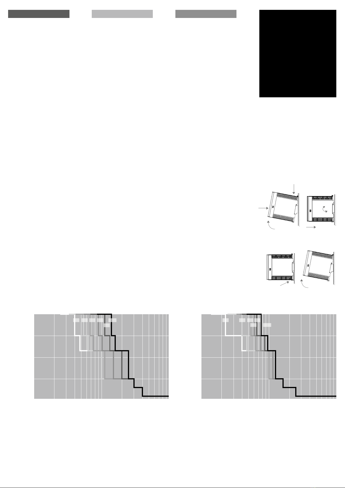
Installation
Installation must be carried out according to the prevailing local conditions and safety
regulations, national accident prevention regulations and the generally accepted rules
of technology. This equipment is a component designed for installation into electrical
systems and machines, and fulfills the requirements of the low voltage guidelines
(2014/35/EU). The required minimum spacing to neighboring components must be
observed to guarant ee the required cooling!
Read this first
Veuillez lire soigneusement ces avertissements et consignes de sécurité avant de
mettre l’appareil en service. L’appareil ne doit être installé que par du personnel
compétent et qualifié. En cas de dysfonctionnement, couper immédiatement la tension
d’alimentation et retourner l’appareil à l’usine pour vérification. L’appareil ne contient
pas de pièces échangeables. En cas de déclenchement d’un fusible interne, l’appareil
présente vraisemblablement un défaut. Les données indiquées sont à but descriptif.
Elles ne doivent pas être interprétées comme des caractéristiques assurées au sens
juridique du terme.
Usage conforme
Cet appareil est conçu pour être installé en armoire et convient à une utilisation sur
des installations électriques générales telles que des commandes industrielles, des
appareils de bureau, de communication ou de mesure. Ne pas utiliser cet appareil à
bord des commandes d’avions, de trains, ou installations nucléaires, dans lesquelles un
dysfonctionnement peut entrainer des blessures graves ou signifier un risque mor tel
Installation
L’installation doit être réalisée conformément aux recommandations locales, aux
directives nationales relatives à la prévention des accidents ainsi que les normes
techniques reconnues. Cet équipement est un composant destiné à un montage
sur des systèmes et des machines électriques. Il est conforme aux conditions de la
Directive Basse tension (2014/35/EU). La distance minimale requise avec les modules
avoisinants doit être respectée afin de ne pas entraver le refroidissement.
A lire avant la mise en service
1
2
3
4
5
6
Sealed cover of the current-selector-switches
Input (+24 Vdc and 0 Vdc)
The 0 Vdc connection of the device merely serves to supply the internal electronic
circuits.
Outputs for connecting the load circuits. The 0 V of the loads must be supplied
directly to the power supply by means of separate lines.
Current-selector-switches
Pushbuttons On/O ff/Reset with int egrated LED
Signaling contacts S1/S2/S3
S1= 0 Vdc - input (On/Off/Reset) 1)
S2= open - output (status output channels) 2)
S3= open - output (common message for tripped or switched off outputs) 2)
User elements
Fig. 1
1
2
3
4
5
6
Capot de protection des sélecteurs
Entrée (+24 V CC et 0 V CC).
La connexion du 0 V CC est utilisée uniquement pour l‘alimentation du disjoncteur
Sor ties pour le raccordement des charges. Le 0 V CC des charges doit être
raccordé directement à l‘alimentation électrique par des câbles séparés.
Sélecteur
Bouton marche/ arrêt / réinitialisation avec LED intégrée
Commande S1 et sorties de signalisation S2/S3
S1 =0 V CC - Entrée (Marche/arrêt/ Réinitialisation) 1)
S2= ouvert - Sortie (indique l’état de fonctionnement de toutes les sorties) 2)
S3= ouvert - Sortie (alarme collectif pour sorties déclenchées ou désactivées) 2)
Eléments de commande
Fig. 1
Operating states,
Signaling, Reactions
Etats de fonctionnement,
signalisation, réactions
1) With inver t ed logic (0Vdc ≙ High, 24Vdc ≙ Low)
2) The outputs S2 and S3 ar e negati ve swi tching outputs (Open-Drain).
The inpu ts pull down the applied pot ential S2 and S3 against the negati ve pot ential .
1) Avec une logique inversée (0 V CC ≙ High, 24 V CC ≙ Low)
2) Les sorties S2 et S3 sont de s sor t ies de commutation nega tives (Drain ouver t ).
Les entrées dessinent le potentiel appliqué S2 et S3 par rapport au potentiel négatif.
1) After the initialization of the device the outputs are switched on (load dependent).
2) The output is automatically deactivated in accordance with tripping-curves-characteristics.
3) The state is saved at power - of f of all output s.
4) After a specific time interval (Thermal relief) change to operational condition Z5. If the unit is switched off
the remaining time is saved and will resume with the next switch on. This reliably prevents overloading if the
uni t is immediately switched back on.
5) The affected output can be reset by pressing the push button twice or through an impulse (>0,5s) on signal
input S1. Change to operational condition Z1.
1) Une fois le module initialisé, les sorties seront activées dépendamment de la charge.
2) La sor tie est désact ivée aut omat iq uement conformément à la carac téristique de déc lenchement
3) L’é tat de fonctionnement de chaque sor tie est enr egistré à la coupure de l’appar eil.
4) Après un délai d’attente (détente thermique), la sortie peut être réactivée. Le temps d’attente restant est
enr egis tré lors de la coupur e de l’appareil et son expiration se fera au redémarrage.
5) La sortie concernée peut être réinitialisée en pressant 2 X sur le bouton ou via une impulsion (>0.5 s) sur la
l‘entrée de commande S1 , passage à l‘état Z1.
State / Description Output LED Signal output S3
(Summation)
Pushbutton pressed
=> go to...
Signal input S1
=> go to...
Z 0 Initialization 1) off off open --- ---
Z 1 Output on, function OK on green 0 Vdc Z 3 Z 3 (via bit-streaming)
Z 2 Output current > rated
current 2)
on green
flashing
0 Vdc Z 3 Z 3 (via bit-streaming)
Z 3
Output was switched
off manually or through
signal input S1 3)
off red open Z 1 Z 1 (via bit-streaming)
Z 4
Output was switched
off automatically (over
current), thermal
relaxation active 4)
off red
flashing
open --- ---
Z 5
Output was switched
off automatically (over
current), thermal
relaxation finished 5)
off orange
flashing
open Z 3 Z 1 (through impulse > 0,5 s)
Z 6 Output malfunction
(internal fuse blown)
off red flasing
fast
open Z 6 ---
Etat de fonctionnement /
Description Sortie LED Sor tie de signal S3
Message collectif
Bouton est actionné
=> aller à...
Entrée de commande S1
=> aller à...
Z 0 Initialisation de module 1) arrêt arrêt ouvert --- ---
Z 1 Sortie activée, Fonction OK marche vert 0 V CC Z 3 Z 3 (via configuration
binaire)
Z 2 Courant de sortie > Courant
nominal 2)
arrêt clignote
vert
0 V CC Z 3 Z 3 (via configuration
binaire)
Z 3
La sortie est déactivée
manuellement ou par l‘entrée de
signal S1 3)
arrêt rouge ouvert Z 1 Z 1 (via configuration
binaire)
Z 4
La sortie est désactivée en raison
d‘un courant de surcharge,
détente thermique active 4)
arrêt clignote
rouge
ouvert --- ---
Z 5
La sort ie est désactivée en raison
d‘un courant de surcharge,
la détente thermique est terminée 5)
arrêt clignote-
orange
ouvert Z 3 Z 1 (par impulsion
>0,5 s)
Z 6
Erreur de l‘appareil (fusible interne
défectueux détecté)
arrêt clignote
rapidement
rouge
ouvert Z 6 ---

787-1664/0000-0011 787-1664/0106-0011
Eingangsdaten Input data Entrée
Eingangsnennspannung Nominal input voltage
Tension nominale d‘entr ée
24 Vdc
Eingangsspannungsbereich Input voltage range
Plage de tension d‘ent rée
18 - 30 Vdc
Maximale Restwelligkeit/Rippel der speisen-
den Eingangsspannung
Maximal residual ripple of supplied input
voltage
Ondulation résiduelle maximale/ondulation
de la tension d‘entrée d‘alimentation 3%
Erforderliche Eingangsspannung zum
Einschalten der Ausgänge
Required input vol tage for turning on of
outputs
Tension d‘entrée requise pour l‘ac tivation
des sorties 20 Vdc
Max. Dauerstrom des Moduls Max. total input current Courant permanent max . du module
40 A 24 A
Max. Dauerstrom pro Klemmenpol Ma x . input current for each pole of terminal Courant permanent max . par pôle de borne 40 A
Überspannungsschutz Suppressordiode Over voltage protection suppressor diode Protection contr e les surtensions
Diode transil 33 Vdc
Ruhestrom im Leerlauf @ 24 Vdc St and- by current @ 24 Vdc Courant de repos à vide @ 24Vdc 35 mA
Verlustleist ung im Leerlauf @ 24 Vdc Power losses in stand- by mode @ 24 Vdc Perte s en puissance à vide @ 24Vdc 0,84 W
Anschlüsse Eingang Terminals input Raccordement entrée WAGO Series 831, max 10 mm² (2 x „+“ ) *
WAGO Series 721, max 2,5 mm² (2 x „-“)
Ausgangsdaten Output data Sortie
Ausgangsnennspannung Nominal ou tput vol tage Tension nominale de sortie 24 Vdc
Ausgangsnennströme einstellbar Nominal output current adjustable Courants nominaux réglable des sorties 4 x (2, 3, 4, 6, 8, 10 A) 4 x (1, 2, 3, 4, 5, 6 A)
Maximaler Spannungsabfall zwischen Ein-
und Ausgang
Maximum voltage drop between input and
output
Chute de tension max imale ent re entrée
et sor tie 200 mV @ 4 x 10 A 120 mV @ 4 x 6 A
Modulinitialisierungszeit Initialization time Temps d‘initialisation de module 250 ms
Zuschaltverzögerung der Kanäle
lastabhängig Turn-on delay of outputs load dependen t Retard d‘ac tivation des canaux
selon la charge min. 50 ms / max . 5 s
Wartezeit nach Abschaltung eines
Ausgangs (Thermische Entspannung)
Kur zschluss (A ) ... Überlas t (B)
Waiting periode af t er swi tch-off of an
output (thermal relaxat ion) short cir cuit
(A) ... overload (B)
Temps d‘attente après mise hors ser vic e
d‘une sortie (dét ent e thermique)
court-cir cuit (A ) ... surcharge (B)
500 ms (A ) … 20 s (B)
Maximale Verlustleistung Maximum power losses Perte s en puissance maximales 10 W @ 4 x 10 A 4,2 W @ 4 x 6 A
Wirkungsgrad Efficiency Rendement 99%
Maximale Las tkapazit ät pro Ausgang Maximum turn- on capacit y for each out put Charge capacitive maximale par sortie > 50 … 500 mF
Integrierte Ausgangssicherungen pro
Ausgang Int ernal ou tput fuse for each output Fusibles de sor t ie int erne par sortie 15 A
Rückspeisefestigkeit Resist ance to rever se feed max. Tension de ret our max. 35 Vdc
Parallelschaltung von Ausgängen Par allel use of output s Mon tage en parallèle de sor ties -
Serienschaltung von Ausgängen Serial use of out puts Mon tage en série de sor t ies -
Anschlüsse Ausgänge Terminals outputs Raccordement sorties Wago Series 721, max 2,5 mm² (4 x „+“ )
Signalisierung Signaling Signalisation
Statusanzeige (pro Ausgang)
LED (rot , grün, orange)
St atus display (for each output)
LED (red, green, orange)
Indicat ion du statut (par sor tie)
LED (rouge, ver t e, orange ) o
Signaleingang S1 (Ein/Aus/Reset)
mit invertierter Logik
(0 Vdc ≙ High, 24 Vdc ≙ Low).
Signal input S1 (On/O f f/ Rese t )
with inverted logic
(0 Vdc ≙ High, 24 Vdc ≙ Low).
Entr ée de commande S1
(Marche/Arrêt/Réinitialisation)
avec une logique inversée
(0 Vdc ≙ High, 24 Vdc ≙ Low).
24 Vdc
Level high = min. 0 Vdc, max . 1 Vdc
Level low = min. 4 Vdc, max . 30 Vdc
Jitter: ± 5 % or ± 5 ms
Signalausgang S2
(Zustand der Ausgänge, kurzschlussfest)
Signal out pu t S2
(status output channels, shor t circui t proof )
Sortie de signalisation S2
(interrogation de l‘état des sorties,
résist ant au cour t-circuit)
Open-Drain:
24 Vdc, max . 25 mA
Signalausgang S3
(Sammelmeldeausgang, kurzschlussfest)
Signal out pu t S3
(summation message, short circuit proof)
Sortie de signalisation S3
(sor tie de message collecti f, résistant au
court-circuit)
Open-Drain:
24 Vdc, max . 25 mA
S3 = 0 Vdc: St atus OK
S3 = ext ernal potent ial: minimum one channel is tripped or swi tched of f
Anschlüsse Signalisierung Terminals signaling Raccordement signalisation WAGO Series 721, max 2,5 mm² (S1, S2, S3)
Umwelt Environment
Environnement
Lagertemperatur Storage temperature Température de stockage -25 °C ... +85 °C
Umgebungstemperatur Operational temperature Température ambiante -25 °C ... +70 °C
Konvektionskühlung Convection cooling Refroidissement par convection o
Luftfeuchtigkeit, keine Betauung Humidity, no condensation Humidit é de l‘air , absence de condensa tion 5 ... 96 %
Einsatz in Bereichen mit
Verschmutzungsgrad 2
For installation in Pollution
Degree 2 environment
Pour installation dans un
environnement de pollution 2
o
Zum Anschluss Kupferkabel mit min. 75 °C
verwenden Use Copper Conduc tor s onl y, rated 75 °C
Utiliser uniquement des câbles de connexion
en cuiv re suppor t ant des plages de tempé-
ratures 75 °C
o
Derating Derating Derating
Max. out pu t curr en t per channel: 10 A
total current (all channels togehther):
max. 40 A @ 40 °C
max. 35 A @ 50 °C
max. 25 A @ 60 °C
max. 20 A @ 70 °C
no derating
Erforderlicher Mindestabstand (seitlich) Required minimum spacing (left/right) Distance minimale requise (latérale) -
Erforderlicher Mindestabstand (oben/unten) Required minimum spacing (over/under) Distanc e minimale requise (en haut /en bas) 40 mm
Allgemeine Daten General data Données générales
Schutzar t nach IEC 60529 Degree of prot ect ion acc. to IEC 60529 Type de protec tion selon EN 60529 IP 20
Schutzklasse nach EN 61140 Protection class acc. to EN 6114 0 Classe de protec tion selon EN 6114 0 III
Normen Safety standards Normes
Sicherheit Safety Sécurité EN 60950-1, EN 50178, EN/IEC 60204-1
EMV EMC CEM EN 61000-6-2, EN 61000-6-3
Schutzkleinspannung (SELV/PELV) Safet y ext ra-low voltage (SELV/PELV) Trè s basse tension de sécurit é (TBTS/ TBT P) IEC 60364- 4 - 41 (DIN VDE 0100-410)
CE gemäß 2014/30/EU (EMV-Richtlinie) CE acc. to 2014/30/EU (EMC-Directive ) Conforme à la dire cti ve 2014/30/EU (CEM) o
Prüfzeichen
Markings Approbation
UL 2367 UL 2367 UL 2367 Special-purpose Solid-state overcurrent protectors
UL 508 UL 508 UL 508 List ed for the use as Industrial Cont rol Equipment ;
U.S.A. (UL 508) and Canada
Mechanische Daten Measures and weights Caractéristiques mécaniques
Befestigung auf Normprofilschiene
DIN EN 60715-T H35-15/ 7,5
Mounting on standard rail
DIN EN 60715-T H35-15/ 7,5
Montage sur rail
DIN EN 60715-T H35-15/ 7,5 o
Gewicht Weight Poids 0,2 kg
Maße (B x H x T)
Tiefe ab Oberkante TH35 inkl. Federleisten
Dimensions (W x H x D)
depth without TH35, but incl. terminals
Dimensions (L x H x P) ;
prof ondeur sans TH35, mais avec borne s 45 x 90 x 115,5 mm
Bestellnummer Order number Référence produit
Bestellnummer Order number Référence produit 787-1664/0000-0011 787-1664/0106-0011
Technische Daten Technical data Données techniques
* WAGO Serie 831:
Mit Adernendhülse max. 6 mm
².
Bei feindrähtigen Leitern bitte geeigneten
Spleißschutz verwenden.
* WAGO Series 831:
With ferrule max. 6 mm
².
Please use suitable anti-splaying method for
fine-stranded conductors.
* WAGO Serie 831:
Avec d‘embouts d‘extrémité 6 mm
² max.
Pour les conducteurs souples, veuillez
utiliser une protection contre l‘épissure.

Sicherungskennlinie
Tripping characteristic
Caractéristique du disjoncteur
Fig. 4a
I
II
III
IV
V
Fig. 4b
II
I
deutsch english français
Der elektronische Schutzschalter ist
mit drei Signal- bzw. Steuerkontakten
ausgestattet.
Über den Steuereingang S1 und den
Signalausgang S2 lassen sich sowohl
betriebsrelevante Informationen aus dem
Schutzschalter digital auslesen als auch
gezielt einzelne Ausgangskanäle ein- oder
ausschalten. Ein Reset von allen ausge-
lösten Ausgängen ist ebenfalls möglich,
sofern für mindestens 0,5 Sekunden
0 Vdc an den Steuereingang S1 einge-
speist wird.
Mittels einer übergeordneten Steue-
rung (z.B. SPS) kann über ein codiertes
Bitmuster (Manchester-Code nach IEEE
802.3) an den Steuereingang S1 und
den Signalausgang S2 der Zustand der
Ausgänge des Schutzschalters gesteuert
und ausgele sen werden, siehe auch die
detaillierte Beschreibung im Handbuch.
Der Signalausgang S3 dient als aktive
Sammelmeldung und signalisiert das
Abschalten mindestens eines Kanals
durch Taster oder aufgrund eines Über-
stroms.
Signalisierungs- und
Steuerkontakte S1/S2/S3
The electronic circuit breaker is equipped
with three signal contacts.
Each output can be switched on and swit-
ched of f (send bit streaming - Manches-
ter-Code in acc. with IEEE 802.3) by using
the remote signal-input S1. This signal
input S1 provides also the possibility to
reset of tripped outputs by placing a de-
fined 0 Vdc signal for 0.5 seconds at the
input. It is possible to read out the state
of each output by using the signal output
S2 (read bit streaming - Manchester-
Code in acc. with IEEE 802.3).
The signal output S3 works as active high
collective message. If minimum one out-
put is tripped or switched off , the state
of this output will change from 0 Vdc to
external potential.
Signal- and control
contacts S1/S2/S3
Le disjoncteur électronique dispose d‘une
commande et de deux signalisations.
L‘entrée de commande S1 ainsi que la
sortie de signalisation S2 permettent de
visualiser en numérique les informations
relatives au fonctionnement du
disjoncteur ainsi que de désactiver
individuellement des canaux de sortie
ciblés. Une réinitialisation de toutes
les sorties déclenchées est possible
en appliquant une tension de 0 V CC
à l’entrée S1 pendant au moins 0,5
seconde.
Au moyen d’un dispositif de commande
supérieur (par exemple une interface
API) il est possible via une configuration
binaire codée (se reporter au code
Manchester conformément à IEE
802.3), de commander et visualiser à
l‘entrée de commande S1 et à la sortie
de signalisation S2, l‘état des sorties du
disjoncteur (se reporter à la description
détaillée du manuel).
La sortie de signalisation S3 est utilisé
pour le message groupe et signale la
désactivation d`au minimum une canal en
raison de l‘actionnement d‘un bouton ou
d`une surintensité.
Commande S1 et sorties de
signalisation S2/S3 T
Hinweis:
Eine detaillierte Beschreibung finden Sie im
Handbuch des Schutzschalters, das auf der
Produktseite unter www.wago.com/epsitron
kostenlos zum Download bereitsteht.
Notice:
You can download the complete manual with
detailed description from our product site under
www.wago.com/epsitron.
Indication:
Vous trouverez une description détaillée dans
le manuel du disjoncteur de protection que vous
pouvez télécharger gratuitement sur la page
produit à l‘adresse www.wago.com/epsitron
Mounting
Fig. 4a
AUF TRAGSCHIENE AUFRASTEN
I) Gerätevorderseite leicht nach oben
drehen
II) Auf Hutschiene aufsetzen
III) Bis zum Anschlag nach unten
schieben
IV) Unten gegen die Befestigungsebene
drücken (klick)
V) Leicht am Gerät rütteln, um Verrie-
gelung zu prüfen
Fig. 4b
DEMONTAGE VON TRAGSCHIENE
I) Verriegelungslasche mit Schrauben-
dreher nach unten ziehen und öf fnen.
II) Gerät aus Tragschiene aushängen.
Montage
Fig. 4a
SNAP ON SUPPORT RAIL
I) Tilt the unit slightly rearwards
II) Fit the unit over top hat rail
III) Slide it downward until it hits the stop
IV) Press against the bottom front side
for locking (click)
V) Shake the unit slightly to check the
locking action
Fig. 4b
REMOVAL FROM DIN RAIL
I) Locking tab with a screwdriver and
pull down to open.
II) Unhook the device from DIN rail.
Montage
Fig. 4a
POUR FIXER LE MODULE SUR LE RAIL
I) Pencher légèrement le module vers
l‘arrière
II) Placer le module sur le bord supérieur
du rail.
III) Encliqueter le module vers le bas
jusqu‘à l‘arrêt.
IV) Afin de verrouiller le module, pousser
sur la par tie inférieure (clic)
V) Vérifier l‘enclenchement en secouant
légerement le module.
Fig. 4b
DEMONTAGE DU RAIL
I) Tirer le dispositif de verrouillage à
l‘aide d‘un tournevis vers le bas
pour ouvrir.
II) Décrocher l‘appareil du rail DIN.
1 10
10
100
1000
10000
100000
100
Auslösezeit (ms)
Tripping time (ms)
Temps de déclenchement (ms)
ü
Ausgangsstrom (A)
Output current (A)
Courant de sortie (A)
ü
2 A 3 A 4 A 6 A
8 A
10 A
787-1664/0000-0011
WAGO Kontakttechnik GmbH & Co. KG
Hansastr. 27
32423 Minden
Germany
Phone: +49 571-887-0
Fax: +49 571-887-169
www.wago.com
Technische Änderungen vorbehalten.
Subject to change.
Sous réserve de modifications techniques.
1 10
10
100
1000
10000
100000
100
Auslösezeit (ms)
Tripping time (ms)
Temps de déclenchement (ms)
ü
Ausgangsstrom (A)
Output current (A)
Courant de sortie (A)
ü
1 A 2 A 3 A
4 A
5 A
6 A
787-1664/0106-0011
This manual suits for next models
1
Other WAGO Circuit Breaker manuals
Popular Circuit Breaker manuals by other brands

Siemens
Siemens 3AH47 series operating instructions

Siemens
Siemens SIPLUS HCS POM4320 Highend Compact operating instructions

Eaton
Eaton Series NRX instruction manual

GE
GE AK-15 installation instructions

Eaton
Eaton VCP-W Series Instructions for installation/operation/maintenance/servicing

Eaton
Eaton T5B Series Instruction leaflet

C-LOGIC
C-LOGIC 3600UK instruction manual

Hubbell
Hubbell Circuit Guard Installation, Testing and Operating Instructions

Siemens
Siemens GM-SG instruction manual

ABB
ABB SACE Emax 2 manual

ABB
ABB SACE Emax 2 Installation, operation and maintenance instructions

GE
GE AKR-30S Installation and maintenance instructions