EPSITRON® Table of Contents 3
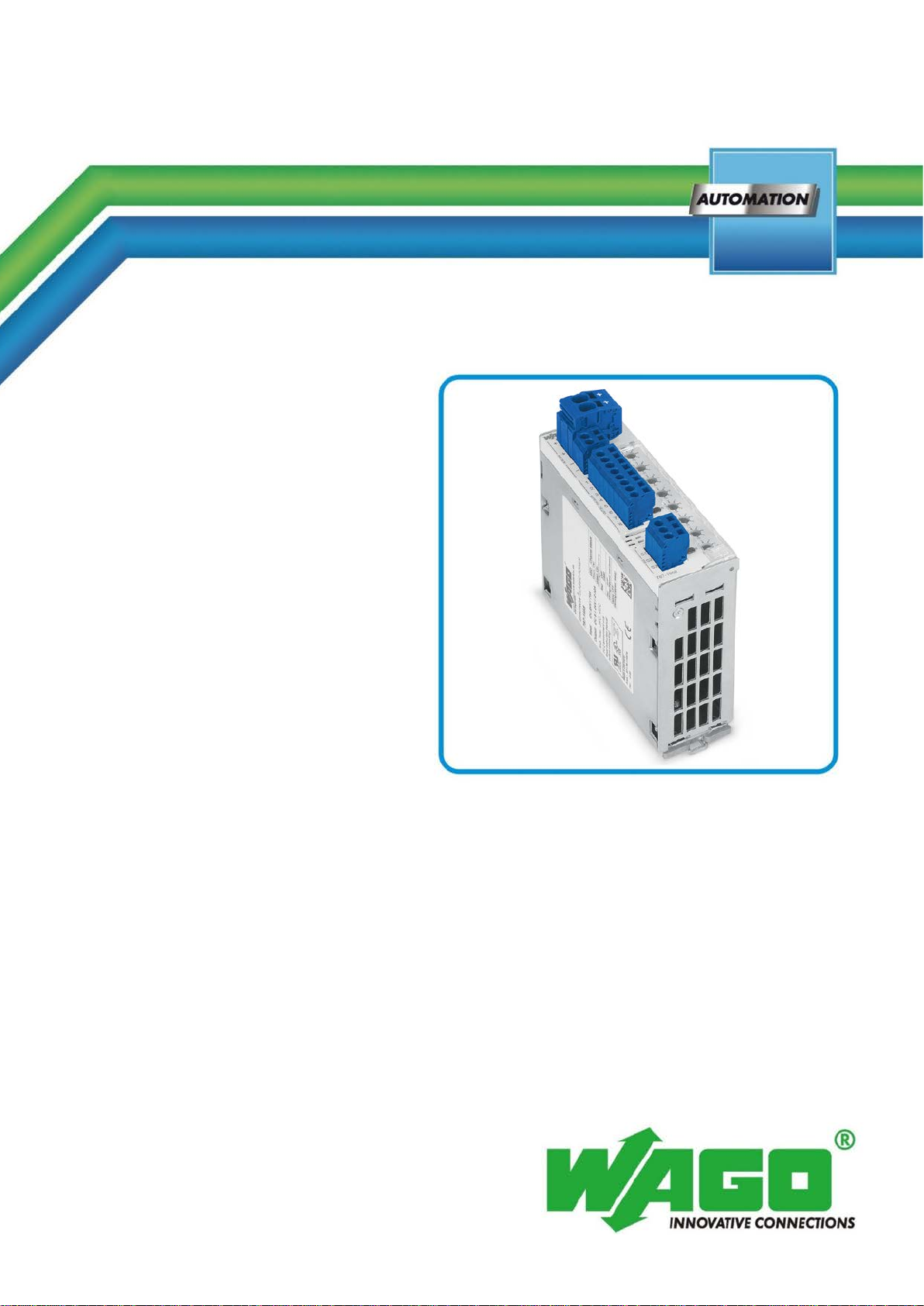
787-1668 Electronic Circuit Breaker
Manual
Version 1.1.0
Pos: 5/ Do ku ment ati on all ge mein /V erzei ch niss e/I nhal tsv erz eich nis - Ü ber schrif t oG und Verz eich nis @ 3\mod_1219151230875_21.docx@ 21063@ @ 1
Table of Contents
Table of Contents................................................................................................... 3
1Notes about this Documentation................................................................. 5
1.1 Validity of this Documentation................................................................. 5
1.2 Copyright................................................................................................... 5
1.3 Symbols..................................................................................................... 6
1.4 Number Notation....................................................................................... 8
1.5 Font Conventions ...................................................................................... 8
2Important Notes........................................................................................... 9
2.1 Legal Bases ............................................................................................... 9
2.1.1 Subject to Changes............................................................................... 9
2.1.2 Personnel Qualifications....................................................................... 9
2.1.3 Use of the 787 Series in Compliance with Underlying Provisions...... 9
2.1.4 Technical Condition of Specified Devices......................................... 10
2.2 Safety Advice (Precautions).................................................................... 11
3Device Description ..................................................................................... 13
3.1 View........................................................................................................ 14
3.2 Connectors............................................................................................... 15
3.2.1 Power supply...................................................................................... 15
3.2.2 Fuse-Protected Outputs ...................................................................... 16
3.2.3 Control and Signaling Contacts.......................................................... 16
3.3 Display Elements .................................................................................... 17
3.4 Operating Elements................................................................................. 18
3.4.1 Buttons................................................................................................ 18
3.4.2 Rotary Switch..................................................................................... 19
3.5 Technical Data ........................................................................................ 20
3.5.1 Device Data ........................................................................................ 20
3.5.2 Technical Data for "Input" ................................................................. 21
3.5.3 Technical Data for "Output"............................................................... 22
3.5.4 Technical Data for "Ambient conditions".......................................... 23
3.5.5 Technical Data for "Signaling" .......................................................... 23
3.6 Approvals................................................................................................ 24
3.7 Standards and Guidelines........................................................................ 25
4Mounting..................................................................................................... 26
4.1 Mounting................................................................................................. 26
4.2 Mounting the Device on the DIN 35 Rail............................................... 26
4.3 Removing the Device from the DIN 35 Rail .......................................... 27
5Connect Devices ......................................................................................... 28
5.1 Connection Example............................................................................... 28
6Function Description ................................................................................. 29
6.1 Undervoltage and Overvoltage Detection............................................... 29
6.2 Trip Curves.............................................................................................. 29
6.2.1 Trip Curve for the 10 A Circuit Breaker 787-1668............................ 29
6.2.2 Trip Curve for the 6 A Circuit Breaker 787-1668/0106-0000 ........... 30