WAGO-I/O-SYSTEM 750 XTR Table of Contents 3
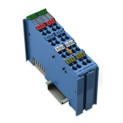
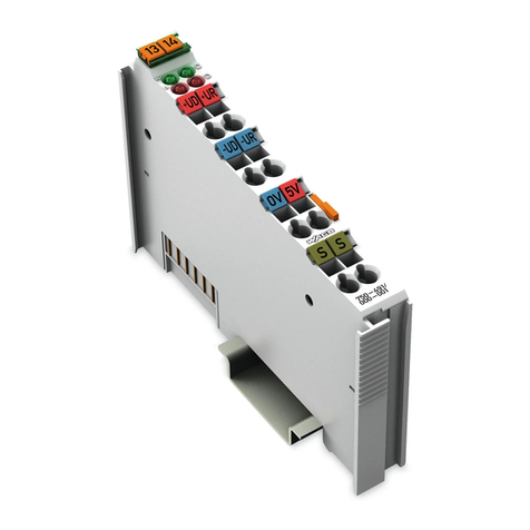
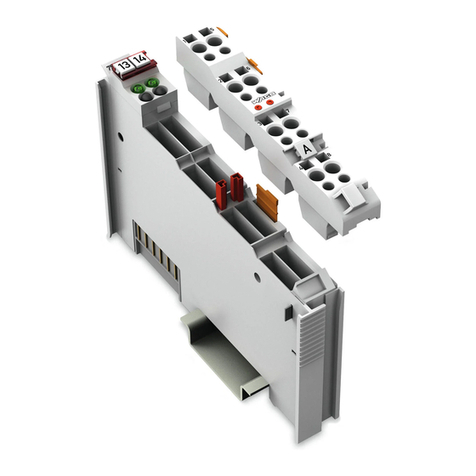
750-614/040-000 Potential Distribution XTR
Manual
Version 1.1.0
Pos: 5/ D ok ume nt ati on allg em ein /V erz eic h nis se /I nhal ts ver z eic hni s - Ü b ers chri f t oG und V erz ei ch nis @ 3\mod_1219151230875_21.docx@ 21063 @ @ 1
Table of Contents
1Notes about this Documentation .............................................................5
1.1 Validity of this Documentation.................................................................5
1.2 Copyright................................................................................................5
1.3 Symbols .................................................................................................6
1.4 Number Notation ....................................................................................7
1.5 Font Conventions ...................................................................................7
2Important Notes ........................................................................................8
2.1 Legal Bases............................................................................................8
2.1.1 Subject to Changes............................................................................8
2.1.2 Personnel Qualifications ....................................................................8
2.1.3Use of the 750 Series in Compliance with Underlying Provisions.......8
2.1.4 Technical Condition of Specified Devices...........................................9
2.1.4.1 Disposal ........................................................................................9
2.1.4.1.1 Electrical and Electronic Equipment..........................................9
2.1.4.1.2 Packaging...............................................................................10
2.2 Safety Advice (Precautions) .................................................................11
3Device Description..................................................................................14
3.1 View .....................................................................................................15
3.2 Connectors...........................................................................................16
3.2.1 Data Contacts/Local Bus..................................................................16
3.2.2 Power Jumper Contacts/Field Supply ..............................................17
3.2.3 CAGE CLAMP®Connectors.............................................................18
3.3 Operating Elements..............................................................................19
3.4 Schematic Diagram ..............................................................................19
3.5 Technical Data .....................................................................................20
3.5.1 Device Data .....................................................................................20
3.5.2 Supply..............................................................................................20
3.5.3 Connection Type..............................................................................21
3.5.4 Mechanical Conditions .....................................................................21
3.5.5 Climatic Environmental Conditions...................................................21
3.6 Approvals .............................................................................................22
3.7 Standards and Guidelines ....................................................................23
4Mounting..................................................................................................29
4.1 Mounting Sequence..............................................................................29
4.2 Inserting and Removing Devices ..........................................................30
4.2.1 Inserting the I/O Module...................................................................30
4.2.2 Removing the I/O Module ................................................................31
5Connect Devices .....................................................................................32
5.1 Connecting a Conductor to the CAGE CLAMP®...................................32
