WalimeXPro 13529 User manual

02/2021
WALSER GmbH & Co. KG
Senefelderstrasse 23
86368 Gersthofen
Germany
info@walser.de
ww.walser.de
Made in China
Gebrauchsanleitung
Instruction Manual
WAND-LAMPENSTATIV 70 – 120 CM
WALL-MOUNTED LAMP SUPPORT, 70 –120 CM

2 3
DGebrauchsanleitung
Mit dem Walimex pro Wand-Lampenstativ 70 –120cm erhalten Sie ein
tragfähiges Wandstativ höchster Qualität. Montieren Sie Leuchten, Blitze
oder anderes Studioequipment an der Wand und sparen Sie Platz am Boden.
Ideal für Studios mit Decken, die sich nicht für Deckenschienensysteme
eignen. Die hochwertige Verarbeitung und Produktqualität wird Sie über-
zeugen und Ihnen viele Jahre Zufriedenheit geben.
Bestimmungsgemäße Verwendung
Dieses Wandstativ, bestehend aus einem ausziehbaren Stativarm, der um
160° geneigt und um 140° geschwenkt werden kann, muss vor Benutzung
fest an einer Wand befestigt werden. Es dient dazu, Equipment wie Leuchten
oder Blitze für Foto- und Filmarbeiten zu tragen. Konstruiert für den Einsatz
zur Nutzung bei Foto- und Filmaufnahmen in privaten Studios und Haus-
halten sowie in industriellen oder gewerblichen Foto- und Filmstudios. Zur
Verwendung in Innenräumen. Speziell für die Anforderungen von Foto- und
Videoaufnahmen entwickelt.
Nicht geeignet zum Befestigen oder Führen von Kameras.
10
2
5 8
3
7
4
6
A) Components
1 Mounting adapter 5/8 inch spigot,
non-twisting
2 Spigot Mount with locking screw
3 Extension arm of the boom
4 Extension lock
5 Boom
6 Strut Lock
7 Strut
8 Articulated joints for height
9 Base plate with mounting holes
10 Articulated joints for swiveling
A) Bauteile
1 Befestigungsadapter 5/8 Zoll Spigot,
verdrehsicher
2 Klemmbefestigung mit Feststellschraube
3 Auszug des Stativarms
4 Verschluss für den Auszug
5 Stativarm
6 Verschluss für Strebe
7 Strebe
8 Gelenkverbindungen für Höhenverstellung
9 Basisplatte mit Montagelöchern
10 Gelenkverbindung für Schwenks
WARNUNG
Stoß-, Quetsch- und Brandgefahr, auch durch herabfallende Teile
■Achten Sie darauf, dass Sie das Wandstativ stets fest und sicher befes-
tigen.
■Verlegen Sie Kabel stets so, dass niemand darüber stolpern kann.
■Achten Sie darauf, dass sich niemand unter dem Wandstativ bzw. dem
Gerät während der Benutzung und auch bei Nichtbenutzung aufhält.
■Die maximale Tragfähigkeit des Wandstatives von 15 kg ohne Auszug
und 8 kg bei vollem Auszug darf nicht überschritten werden.
■Bitte beachten Sie, dass die Wand, an der Sie das Stativ anbringen, von
ausreichender Stabilität ist und entsprechende Tragkraft bietet. Nutzen
Sie nur Schwerlastanker, die sich für eine derartige Belastung durch den
starken Hebel eignen. Standard-Trockenbauwände sind ungeeignet.
■Achten Sie auf eine strikt lotrechte Montage der Basisplatte.
9
9
1

4 5
Achten Sie auf sicheren Halt der beiden Verschlüsse (4) und (6), bevor Sie
Equipment auf dem Stativarm montieren. Halten Sie den Stativarm stets fest,
wenn Sie einen der beiden Verschlüsse lösen.
Das Gelenk an der Basisplatte erlaubt ein Schwenken um ± 70°. Zum
Schwenken drücken oder ziehen Sie den Stativarm einfach vorsichtig in die
gewünschte Richtung. Dies ist mit montiertem Equipment möglich.
Montage von Equipment auf dem Stativarm
Am Ende des Auszugs bendet sich eine Spigot-Hal-
terung (2). In dieser kann ein 16mm-Befestigungs-
adapter (1), auch 5/8 Zoll Spigot genannt, in zwei
Ausrichtungen befestigt werden.
Mithilfe dieses Adapters lassen sich Geräte wie
Studioblitze, Leuchten, Softboxen, Mikrofone uvm.
per genormter Halterung befestigen. Schrau-
ben Sie zur Befestigung Ihres Equipments die
Arretierungsschraube der Gerätehalterung Ihres zu
befestigenden Zubehörs etwas heraus und führen Sie
die Gerätehalterung Ihres Equipments von oben auf den Stativadapter (1).
Ziehen Sie anschließend die Schraube wieder fest an. Achten Sie hierbei auf
die korrekte Positionierung der Halterung. Die Schraube muss am schlanken
Teil des Befestigungsadapters (1) festgeschraubt werden. Hierdurch wird ein
Lösen der Halterung inkl. Ihres Equipments zuverlässig verhindert. Der Spi-
got verfügt außerdem über zwei abgeachte Stellen. Wenn Sie die jeweilige
Halteschraube auf so eine ache Stelle senken, ist der Spigot verdrehsicher
angebracht.
Beachten Sie die maximale Belastbarkeit, siehe Technische Daten.
Benutzungshinweise und Pege des Stativs
■Befestigen Sie das Stativ nur an entsprechend tragfähigen Wänden. Durch
die großen Hebelkräfte muss die Basisplatte mit entsprechend tragfähi-
gen Schwerlastankern an der Wand befestigt werden.
■Beachten Sie die Hinweise bzgl. der maximalen Belastbarkeit Ihres Stativ-
modells (siehe Technische Daten)
■Berücksichtigen Sie, dass der angegebene maximale Belastungswert für
den eingezogenen Arm gilt. Je nach Länge des Auszugs kann die Belas-
tungsgrenze vom angegebenen Höchstwert abweichen.
■Beachten Sie, dass Feuchtigkeit die Haltekraft der Verschlüsse reduziert.
Bei Belastung kann der Arm daher nach unten wandern, der Auszug kann
Montage des Stativs
Befestigen Sie die Basisplatte mit geeigneten und
tragfähigen Schwerlastankern an der Wand. Sie
können entweder 4 große oder 8 kleine Anker
verwenden. Zum Durchmesser der Öffnungen in der
Basisplatte siehe Bild. Das Wandstativ wird komplett
zusammengesetzt geliefert und ist nach abgeschlos-
sener Montage an der Wand sofort einsatzbereit.
Das Wandstativ kann mit dem Stativarm oben oder
unten montiert werden. Wir empfehlen die „hän-
gende“ Montage mit dem Stativarm unten. Achten
Sie vor der Montage darauf, nach oben genug Platz
für ein Anwinkeln des Stativarms sowie montierte
Geräte zu lassen. Geräte können auch hängend
montiert werden.
Verstellung von Auszug und Neigungswinkel, Schwenken
Der Stativarm verfügt über einen Auszug und kann
außerdem um ± 80° (aus der Waagerechten) ange-
winkelt werden. Verstellen Sie den Auszug und den
Neigungswinkel nur ohne montiertes Equipment!
Um den Auszug zu verstellen, öffnen Sie den Ver-
schluss für den Auszug (4) und ziehen diesen so weit
heraus, wie Sie es brauchen. Drehen Sie den Auszug
in die Stellung, die Sie brauchen. Dann drehen Sie
den Verschluss (4) wieder fest.
Um den Neigungswinkel zu verstellen, halten Sie den
Stativarm fest. Öffnen Sie nun den Verschluss für die
Strebe (6). Heben oder senken Sie den Stativarm, so
weit Sie es benötigen. Drehen Sie dann den Verschluss
(6) wieder fest.
8 mm
5 mm
WARNUNG
Klemm- und Quetschgefahr, Gefahr von Beschädigungen!
Achten Sie beim Verstellen des Wand- Lampenstativs auf Ihre Hände.
Achten Sie beim Schwenken, Neigen und Ausziehen des Stativs auf
Hindernisse.

6 7
ebenfalls Richtung Boden rutschen. Trocknen Sie daher ggf. Arm und
Auszug mit einem weichen, saugfähigen Tuch (z.B. aus Baumwolle).
■Generell sind alle Elemente dieses Lampenstativs wartungsfrei. Aller-
dings ist das regelmäßige Entfernen von Sand, Staub und anderen
Verunreinigungen zu empfehlen. Wenn Sie ein kratzendes oder knir-
schendes Geräusch beim Bewegen des Auszugs feststellen, entfernen
Sie die Verunreinigungen bitte mit einem weichen, angefeuchteten Tuch.
Überprüfen Sie auch den festen Sitz der Verschlüsse (4 und 6) und ziehen
Sie diese ggf. mit einem entsprechenden Werkzeug (nicht enthalten) nach.
Der Auszug kann nur durch komplette Demontage des Verschlusses (4)
entnommen werden. Ein maximales Öffnen der Schraube reicht dafür
nicht.
■Verstellen Sie den Ausleger in Länge und Höhenwinkel nur ohne mon-
tiertes Equipment. Allein das vorsichtige Schwenken ist mit montiertem
Equipment möglich. Vorsicht: Es besteht die Gefahr einer Beschädigung
des Equipments sowie Verletzungsgefahr.
■Beachten Sie bei der Befestigung von Equipment per 1/4 Zoll Gewinde,
dass diese über eine geringere Belastbarkeit verfügen als der 16 mm
Zapfen (5/8 Zoll Spigot) Anschluss. Für die Befestigung von schwerem
Equipment ist eine entsprechend hochwertige Halterung notwendig.
Technische Daten
Walimex pro Wand-Lampenstativ 70 –120cm
Artikel Nummer 13529
Typ Wand-Lampenstativ
Neigungswinkel ± 80°
Schwenkwinkel ± 70°
Maximaler Auszug des Auslegers 120 cm
Anschlüsse am Auszug 5/8“ Spigot-Fassung mit 5/8“
Spigot inkl. 1/4“ und 3/8“ Gewinde
Max. Belastbarkeit Ausleger 15 kg
Max. Belastbarkeit Ausleger
max. ausgefahren 8kg
Material Stativ und Ausleger Aluminium, Metall
Lieferumfang:
1 x Walimex pro Wand-Lampenstativ 70 –120 cm
2 x Ersatzbeilagscheiben
1 x Gebrauchsanleitung

8 9
Wir sind für Sie da!
Sollten Sie Hilfe oder eine kostenfreie, individuelle Beratung durch unser ge-
schultes Fachpersonal benötigen, dann freuen wir uns, wenn Sie mit unserem
Serviceteam Kontakt aufnehmen.
Wir helfen Ihnen gerne!
Ihr Team von WALSER
E-Mail/Homepage
info@walser.de
www.walser.de
Unsere Postanschrift:
WALSER GmbH & Co. KG
Senefelderstraße 23
86368 Gersthofen
Deutschland
Unser Garantieversprechen
WALSER ist bekannt für seine hochwertige Verarbeitung, beste Funktionalität
und einen kundennahen Service. Um unserem außergewöhnlichen Service
ni-
veau zusätzlichen Ausdruck zu verleihen, geben wir für dieses Walimex pro
Produkt eine Garantie von 2 Jahren. Diese Garantie ist nur in Verbindung mit
Ihrem Kaufbeleg gültig.
Wenn Sie unsere Garantie in Anspruch nehmen wollen, kontaktieren Sie uns
bitte per Mail unter info@foto-walser.de.
Unser umfassendes Garantieversprechen und den Garantieumfang nden Sie
unter www.foto-walser.de/garantie
Niclas Walser
Inhaber
EN
Instruction Manual
With the Walimex pro Wall Lamp Support 70 –120cm, you acquired a sturdy
wall-mounted lamp support of the highest quality. Mount lights, ashes or
other studio equipment on the wall and save space on the ground. Ideal
for studios with ceilings that are not suitable for ceiling rail systems. The
high-grade workmanship and product quality will convince you and give you
many years of satisfaction.
Intended use
This wall mount, consisting of an extendable boom, which can be inclined
by 160 ° and swiveled by 140 °, is ideal for use in studios and must be rmly
attached to a wall before use. It is used to mount equipment to a wall, such
as lamps or ashes for photo and lm work. Constructed for use in photo
and lm shoots in private studios and households as well as in industrial or
commercial photo and lm studios. For indoor use. Specially designed to
meet the requirements of photographic and video work.
Not suitable for mounting or guiding cameras.
WARNING
Risk of impact, pinching and re, also due to falling parts
■Make sure to attach the wall stand rmly and securely.
■
Make sure that no one can trip over cables connected to a mounted unit.
■Ensure that no one stands under the unit during use or when it is not
in use.
■The maximum load capacity of the wall stand of 15 kg at minimum
extension to 8 kg at maximum extension must not be exceeded.
■
Please ensure that the wall to which you attach the support is of sufcient
structural stability and offers the appropriate load-bearing capacity.
Only use heavy-duty anchors that are suitable for such a load due to the
strong lever force. Regular drywall is unsuitable.
■Ensure that the base plate is mounted strictly perpendicular.

10 11
To swivel, simply push or pull the stand arm gently in the desired direction.
This is possible with the equipment mounted.
Mounting equipment on the boom
At the end of the boom there is a mounting
adapter (2) which can hold a standard 5/8 inch
(16 mm) spigot in two orientations. With the
help of this adapter, equipment such as studio
ashes, lights, softboxes, microphones, etc.
can be mounted using a standardised bracket.
To attach your equipment, slightly unscrew
the locking screw of the equipment holder of
the accessory to be attached and guide the
equipment holder of your equipment onto the
stand adapter from above (1). Then tighten the
screw again. Make sure that the holder is posi-
tioned correctly. The screw must be tightened on the slim part of the moun-
ting adapter (1). This reliably prevents the bracket and your equipment from
coming loose. The spigot also features two attened sections. If you lower the
respective retaining screw onto such a at section, the spigot is attached in a
twist-proof manner. You can attach suitable equipment to this.
Please note the maximum load capacity, see technical specications.
Instructions for use and care of the support stand
■Only attach the support to walls with sufcient load-bearing capacity. Due
to the strong leverage forces, the base plate must be attached to the wall
with heavy-duty anchors with the appropriate load-bearing capacity.
■Observe the instructions regarding the maximum load capacity of your
tripod model (see technical specications).
■Take into account that the specied max load value applies to the retrac-
ted extension arm. Depending on the length of the extension arm, the
load limit may deviate from the specied maximum value.
■Note that moisture reduces the holding force of the locks. Under load, the
boom can therefore tilt downwards as well as extend towards the oor. If
necessary, dry off the boom and extension with a soft, absorbent cloth
(e.g. cotton).
■
In general, all elements of this lamp support are maintenance-free. Howe-
ver, regular removal of sand, dust and other impurities is recommended. If
you notice a scratching or crunching noise when moving the boom, please
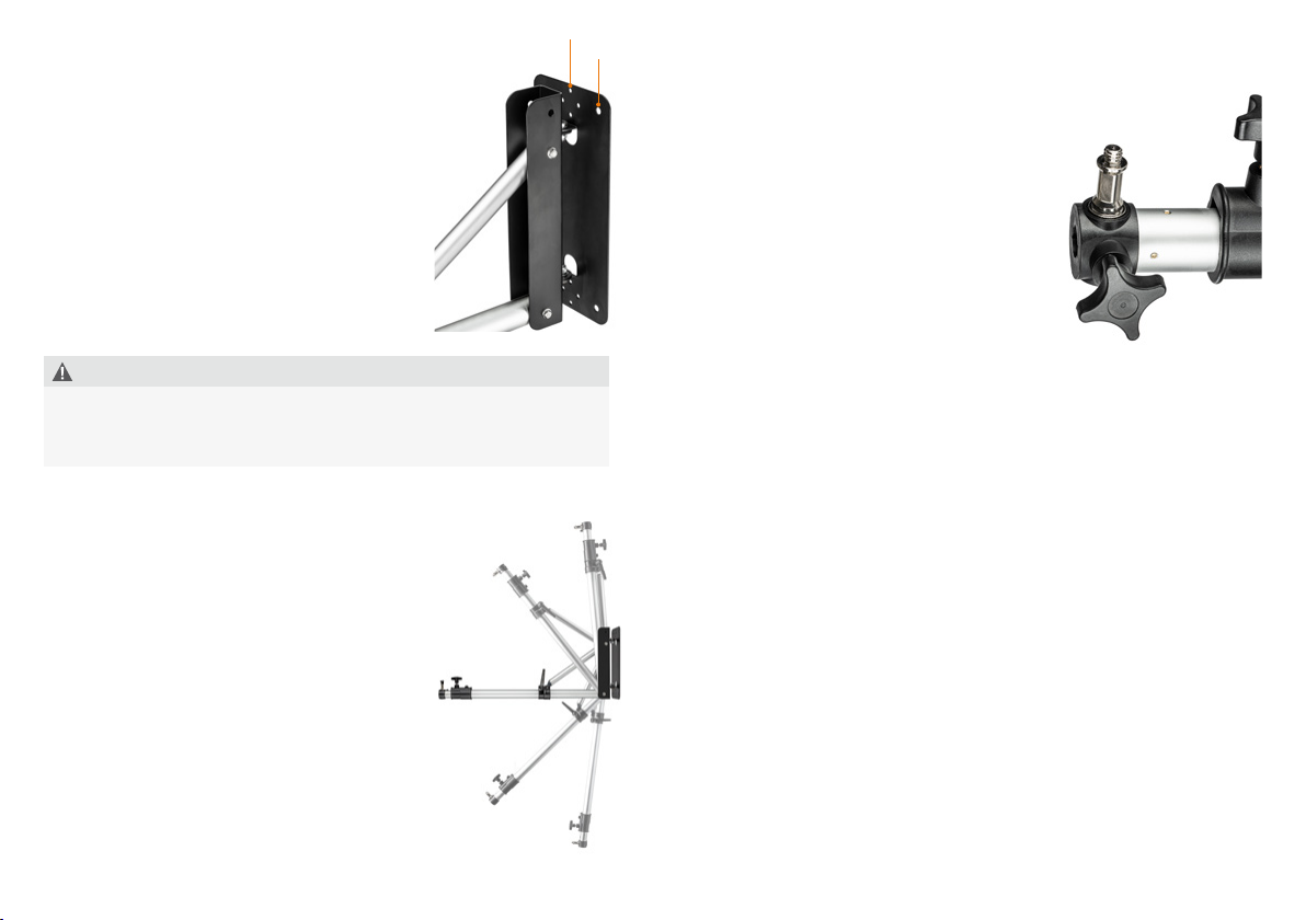
Installing the support
Attach the base plate to the wall with suitable and
load-bearing heavy-duty anchors. You can use
either 4 large or 8 small anchors. For the diameters
of the openings in the base plate, see the picture.
The wall stand is delivered completely assembled
and is ready for use immediately after successful in-
stallation on the wall. The wall stand can be moun-
ted with the boom at the top or at the bottom. We
recomment the „hanging“ assembly with the boom
at the bottom. Before mounting, make sure to
leave enough space at the top for tilting the boom
as well as mounted devices. Devices may also be
mounted in a hanging conguration.
Adjustment of extension and tilt angle, swiveling
The boom extends and can also be tilted up and down
by ± 80° (from the horizontal). Do not adjust the
extension and the tilt angle if the equipment is
mounted!
To adjust the extension, open the lock for the
extension (4) and pull it out as far as you need.
Twist the extension into the position you need.
Then tighten the lock (4) again.
To adjust the tilt angle, hold the tripod arm rmly.
Now open the lock for the strut (6). Raise or lower
the boom as much as you need. Then tighten the
lock (6) again. Make sure that both locks (4) and
(6) are securely fastened before mounting equip-
ment on the boom. Always hold the boom rmly
when loosening either of the two locks. The joint on the
base plate allows the boom to swivel ± 70°.
8 mm
5 mm
WARNING
Danger of pinching and crushing! Watch your hands when adjusting the
lamp stand.
Watch for obstacles when tilting, swiveling or extending the boom.

12 13
remove the impurities with a soft, moistened cloth. Also check the tight t
of the catches (3) and tighten them with an appropriate tool (not included)
if necessary. The extension can only be removed by completely dismantling
the catch (4). Opening the screw to the max is not sufcient for this.
■Adjust the extension in length and vertical angle only without mounted
equipment. Swiveling is possible with mounted equipment. In all other
movements like tilting and extending there is a higher risk of damage to
the equipment and injury.
■
When attaching equipment via the 1/4 inch thread, please note that this
connection has a lower load capacity than the 16 mm spigot (5/8 inch
spigot) connection. For the attachment of heavy equipment, an appropriate
high-quality bracket is necessary.
Technical specications
Walimex pro Wall Lamp Support, 70 –120cm
Item number 13529
Type Wall-mounted lamp support
Tilt angle ± 80°
Pivot angle ± 70°
Maximum extension of the boom 120 cm
Connections 5/8“ spigot socket on boom,
with 5/8“ spigot incl. 1/4“
and 3/8“ thread
Max. Load capacity of boom 15 kg
Max. Load capacity of boom max.
extended 8kg
Material support and boom aluminium, metal
Scope of delivery:
1 x Walimex pro Wall Lamp Support 70 –120 cm
2 x Spare washers
1 x Instruction manual
We are here for you!
If you need help or a free, individual consultation from our trained specialist
personnel, please contact our service team.
We are happy to help!
Your WALSER Team
Email/Homepage
info@walser.de
www.walser.de
Our postal address:
WALSER GmbH & Co. KG
Senefelderstrasse 23
86368 Gersthofen
Germany
Our warranty promise
WALSER is known for its high-quality workmanship, optimal functionality and
customer-oriented service. To highlight our exceptional service level, we offer
a 2 year warranty for this Walimex pro product. This warranty is only valid in
combination with your purchase receipt.
If you would like to utilize our warranty, contact us by email at
info@foto-walser.de. Our comprehensive guarantee as well as its scope can
be found at www.foto-walser.de/en/warranty.
Niclas Walser
Founder and Owner

14 15
Notes:
Notizen:
Table of contents
Languages:
Other WalimeXPro Lighting Equipment manuals

WalimeXPro
WalimeXPro Shining White 380 User manual

WalimeXPro
WalimeXPro 15537 User manual

WalimeXPro
WalimeXPro VC-1000Q User manual

WalimeXPro
WalimeXPro Versalight 500 Daylight User manual

WalimeXPro
WalimeXPro Campaigner User manual

WalimeXPro
WalimeXPro Emerger User manual

WalimeXPro
WalimeXPro Niova 800 Plus Daylight User manual

WalimeXPro
WalimeXPro LED Round 200 User manual

WalimeXPro
WalimeXPro Mover 400 Use and care manual

WalimeXPro
WalimeXPro LED 500 User manual