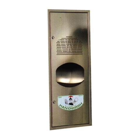
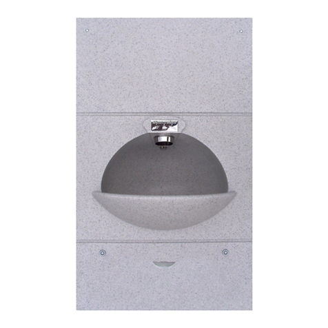
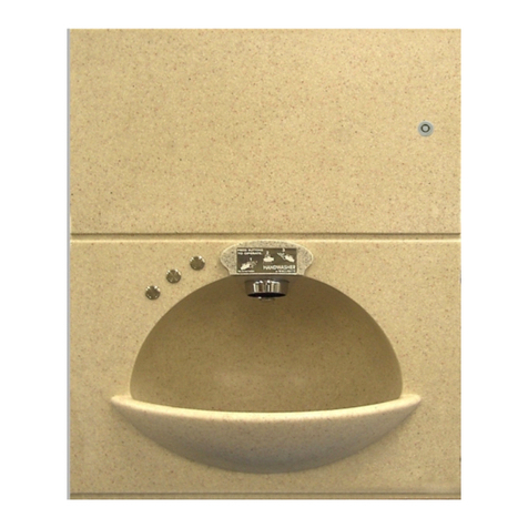
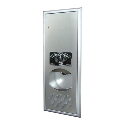
Wallgate PSH-30 Series User manual

Product Manual
PSH-30 series
Hand Wash Dryer

Revision 1
2
Product Manual PSH-30 series Hand Wash Dryer

Revision 1
3
Product Manual PSH-30 series Hand Wash Dryer
Safety Information
WARNINGS!
The appliance must be earthed.
The means for disconnection from the mains supply must be incorporated in
the fixed wiring in accordance with the wiring rules.
If the supply cord is damaged, it must be replaced by the manufacturer, its
service agent or similarly qualified persons in order to avoid a hazard.
The appliance must not be installed in locations where freezing can occur.
We recommend that adequate frost protection is provided in the building to
ensure freezing does not occur.
The resistivity of the water supply must not be less than 1300Ωcm.
Minimum water pressure: 100kPa.
Maximum water pressure: 1000kPa.
This appliance can be used by children aged from 8 years and above and
persons with reduced physical, sensory or mental capabilities or lack of
experience and knowledge, if they have been given supervision or instruction
concerning use of the appliance in a safe way and understand the hazards
involved.
Children shall not play with the appliance.
Cleaning and user maintenance shall not be made by children without
supervision.

Revision 1
4
Product Manual PSH-30 series Hand Wash Dryer
Table of Contents
Safety Information ................................................................................................................................... 3
1. Disclaimer & Copyright Notice......................................................................................................... 5
2. Conventions..................................................................................................................................... 6
2.1. Warning ............................................................................................................................................ 6
2.2. Note.................................................................................................................................................. 6
2.3. Numbered procedures...................................................................................................................... 6
2.4. Bullet lists ......................................................................................................................................... 6
2.5. Menu items....................................................................................................................................... 6
3. Glossary........................................................................................................................................... 7
4. Technical Specification.................................................................................................................... 8
5. Overview.......................................................................................................................................... 9
6. Package Contents ......................................................................................................................... 10
7. Installing the Support Frame, Water, Waste and Electrical Connections ..................................... 11
7.1. Pre-installation Guidelines.............................................................................................................. 11
7.1.1. Water connections pre-installation.............................................................................................. 11
7.1.2. Electrical connections pre-installation......................................................................................... 11
7.1.3. Aperture pre-installation .............................................................................................................. 12
7.1.4. Fascia Mounting Guidelines ....................................................................................................... 13
7.1.5. Control Module Mounting Methods ............................................................................................. 15
7.1.6. Connecting the control module to the fascia............................................................................... 18
7.1.7. Soap Hook Mounting Guidelines................................................................................................. 24
7.2. Mains Water Connection to Control Module .................................................................................. 25
7.3. Commissioning for use................................................................................................................... 26
8. Programmed Settings.................................................................................................................... 28
8.1. Operation........................................................................................................................................ 30
8.1.1. Dryer Operation........................................................................................................................... 30
8.1.2. Air Heater Operation.................................................................................................................... 30
8.1.3. Hygiene Purge............................................................................................................................. 30
8.2. Advanced Adjustment..................................................................................................................... 31
8.2.1. Hygiene Purge Adjustment.......................................................................................................... 33
9. Care, Routine Maintenance, Service and Repair.......................................................................... 34
9.1. Care and Cleaning.......................................................................................................................... 34
9.2. Routine Maintenance...................................................................................................................... 34
9.3. Service and Repair......................................................................................................................... 35
9.4. Soap replenishment........................................................................................................................ 35
9.5. Spare Parts..................................................................................................................................... 36

Revision 1
5
Product Manual PSH-30 series Hand Wash Dryer
1.Disclaimer & Copyright Notice
Every effort has been made to supply the information within this manual which is
correct. Wallgate Limited will not be liable for any damage or loss that arises if the
person installing, operating, or maintaining the unit has not read or not complied with
the manual.
In any event, and without prejudice to any warranties in Wallgate Limited’s terms and
conditions of sale, Wallgate Limited’s liability for all damages and losses (including
negligence) shall not in any circumstances exceed the amount paid by the customer
for the unit.
Wallgate reserves the right to alter, update or improve its product specification at any
time without prior notice. This manual is specific to the product that it has been
supplied with at the date of supply.
Without prejudice to any warranties in Wallgate Limited’s terms and conditions of
sale, any warranty will be invalidated if the equipment is installed or serviced by
unqualified personnel.
No part of this publication and the information contained may be reproduced,
transmitted, stored in a retrieval system, used or disclosed wholly or partly without
prior written permission from Wallgate Limited.
For full warranty details please see Wallgate Limited Terms and Conditions.
Please ensure this manual is passed to the end-user. The manual forms an integral
part of the product and should be kept for its working life. Additional copies of this
and other supporting documents are available by contacting Wallgate Ltd or by
visiting www.wallgate.com

Revision 1
6
Product Manual PSH-30 series Hand Wash Dryer
2.Conventions
Certain conventions are used in this manual to make it easier to read and
understand. It is recommended that you read and understand these warnings before
you install and commission the Wallgate PSH-30.
2.1. Warning
A warning with white text on a red background is used to give information about
hazards that can cause injury or death. Read and understand these warnings before
you install and commission the PSH-30. Failure to heed these warnings can have
serious consequences.
WARNING! This is a warning!
2.2. Note
A note with black text on a yellow background is used to draw your attention to
important and useful information.
NOTE: This is a note.
2.3. Numbered procedures
Steps in procedures are numbered, starting from 1.
1. This is step 1.
2. This is step 2 etc.
2.4 Bullet lists
2.4. Bullet lists
•A bullet list is used to give information that is not sequential.
2.5. Menu items
Menu items, submenu items and settings, where available, are given in bold.

Revision 1
7
Product Manual PSH-30 series Hand Wash Dryer
3.Glossary
The glossary lists all words, abbreviations and technical terminology used in this
manual, along with a short description of these terms.
Term
Description
Anti-Ligature
Where we use this phrase in connection with our
products it means that we have designed and
tested the product in order to reduce any risk of that
product being used as a ligature attachment point.
Our anti-ligature products have been designed to
reduce the likelihood of a ligature attachment,
however it is the responsibility of the purchaser or
service provider to ensure it is risk assessed and
suitable before use.
Piezo electric Push
button
A piezoelectric pushbutton converts the force
applied to the face of the pushbutton into an
electrical signal. Piezoelectric pushbuttons are
used in the PSH to operate the outlets.
Fascia
The user facing part of the hand wash unit, forming
the bowl and containing the outlets for soap, water
and air, the activation button(s) and waste outlet.
Control Module
The Control Module refers to the complete soap,
water, dryer module mounted remotely from the
fascia
Push fit
Push fit type fittings are a plumbing pipe connector
that pushes onto the copper tube and has an
integral rubber seal to ensure a watertight
connection. The PSH-30 utilizes individual push fit
components and fittings.
BSP
The British Standard Pipe (BSP) thread is a family
of standard screw thread types that has been
adopted internationally for interconnecting and
sealing pipe ends by mating an external (male) with
an internal (female) thread.1
Power up
The external electricity supply is provided to the
PSH-30
1
Description sourced from Wikipedia at http://en.wikipedia.org/wiki/British_standard_pipe_thread

Revision 1
8
Product Manual PSH-30 series Hand Wash Dryer
4. Technical Specification
Weight
Item
Fascia & frame
Control Module
Full soap container
Total
Weight
23.0kg
13.0 kg
2.6 kg
38.6kg
Fascia
Dimensions
Width
Height
Depth
420mm
430mm
300mm
Control Module
Dimensions
Width
Height
Depth
344 mm
517 mm
232 mm
Water Supply
Minimum pressure
Maximum rating
Inlet connection size
Dynamic
1 Bar / 100 kPa
10 Bar / 1000 kPa
Suitable for 15mm copper pipe
Electrical
Power
requirement
Control module; 220–240V 50/60Hz, single phase, 1.2 kW UK plug
socket.
Water Heater; 230V 50/60Hz, single phase 2.8kW, Fused spur.
Regulatory
compliance
Complies with:
RoHS
LVD 2014/35/EU & EMC 2014/30/EU directives.
Flow rate
Handwash regulated to 1.9lpm
Drinking water regulated to 0.8lpm

Revision 1
9
Product Manual PSH-30 series Hand Wash Dryer
5. Overview
The Wallgate PSH-30 is an integrated hand wash dryer unit with piezo button
operation.
The PSH was commissioned by The UK Home Office for use in police holding cells
as an extremely safe in-cell hand wash solution. It includes integral soap dispenser,
instantaneous warm water heater and air dryer, all managed integrally. Options also
include a water only version for use with our range of powerful activation and
controls.
When the piezo button is pressed the hand washing and drying cycle activates,
supplying soap, warm water and dryer-air in amounts and intervals preset as
required.
The unit can be installed in a variety of wall types, (depending on configuration) and
most servicing can be carried out without removing the Control Module or Fascia
from its installed position.
Figure 1: Installation of PSHD30 variant mounted to fascia fixing brackets

Revision 1
10
Product Manual PSH-30 series Hand Wash Dryer
6. Package Contents
Before you begin the installation, make sure that you have the following items:
✓1 Fascia
✓1 Installation instructions
✓1 Control Module
✓1 Container of liquid soap (2.5 litres)
✓1 x fittings and hoses kit (INSKIT)

Revision 1
11
Product Manual PSH-30 series Hand Wash Dryer
7. Installing the Support Frame, Water, Waste and
Electrical Connections
7.1. Pre-installation Guidelines
7.1.1. Water connections pre-installation
Warning! This appliance is not to be installed in locations where freezing can
occur.
We recommend that adequate frost protection is provided in the building to ensure
freezing does not occur.
The installer must:
•Provide a mains cold water supply mounted behind a short distance from the
control module. Terminate the water supply with a suitable isolating tap. For
optimum operation, a dynamic water flow pressure of between 1 & 3 bar is
required.
•Prior to final connection of the water supply to the PSH unit, the water supply
pipes must be flushed through to remove any debris & air locks.
Note: Request advice from Wallgate before you connect the unit to a gravity-
fed water supply.
7.1.2. Electrical connections pre-installation
Warning! All electrical work must be carried out by a qualified electrician and
should be installed in accordance with the current Nationally Approved
Regulation
The installer must:
•Provide an electrical supply of 220–240VAC 50/60Hz with a switched fused spur
for the control module. The fused spur must be a 13Amp, double pole connection
point that is local to the Control Module (the contact separation of the fused spur
switch should be at least 3mm). Earth bonding for this type of unit must comply
with the nationally approved regulations.
•Provide an electrical supply of 220–240VAC 50/60Hz with a switched fused spur
for the water heater. As detailed in the Zip ES3 product manual.
Warning! The switched fused spurs MUST be easliy accessible in case of
emergency

Revision 1
12
Product Manual PSH-30 series Hand Wash Dryer
7.1.3. Aperture pre-installation
Note: When selecting a mounting position, it is important to consider the
suitability of the wall construction. It must support the weight of the assembled
unit as shown in the technical specification. The control module has a mass of
13.0kg and the bowl has a mass of 23.0kg
Note: Water and mains power are located on bottom of the Control Module.
Make an accurate opening in the wall surface according to the dimensions shown in
drawing Fig.2 noting the appropriate mounting height to comply with local guidance
or regulations. It is important that the aperture is square and within tolerance to the
stated dimensions
Note: Complete all surface finishes such as screed, plaster or tiling before
attaching the fascia to the wall.

Revision 1
13
Product Manual PSH-30 series Hand Wash Dryer
7.1.4. Fascia Mounting Guidelines
Figure 2: PSH-30 installation dimensions

Revision 1
14
Product Manual PSH-30 series Hand Wash Dryer
1) Remove the basin fascia, with attached waste pipe, M10 studs, installation
brackets and air ducting relevant to the variant being installed from the
packaging.
To fit the four threaded studs into the mounting points on the rear side of the hand
basin, apply ‘Loctite 270’ onto the first 15mm of thread on each stud end to fit into the
sink corner fixing points. Screw each one in by hand until it stops & then un-screw
the stud by two full turns, Note the recommended cure time of 6 hours at room temp.
of 22°C or up to 24 hours at room temp. of 5°C for the Loctite to set.
NOTE: It is very important to install the studs correctly to prevent the
stud damaging the fascia.
Models without cold water outlet. At the front top LH basin fascia position is
fitted 1 stainless steel operating button and bezel, marked ‘HANDWASH’ or
‘HANDWASH & DRIER’, (depending on model) at front RH position a blank
bezel plate to be fitted with either a plain plate or a plate with legend ‘NOT
DRINKING WATER’.
Cold water outlet models. At the front top LH basin fascia position is fitted 2
stainless steel operating buttons and bezels, front LH marked ‘HANDWASH’
or ‘HANDWASH & DRIER’, (depending on model) front RH with a plain bezel.
2) Fit the solid surface basin fascia, with studs in place, fully into the aperture,
the flat underside of basin area sitting on the bottom of the aperture. Secure
the unit to the wall by placing the vertical retaining brackets onto the studs & fit
M10 fixings
NOTE: It is important to tighten the fixings adequately but avoid distorting
the metal brackets through excessive tightening. Tighten the M10 nuts to a
torque of 17Nm in a circular sequence. Do not overtighten as this may
cause damage to the fascia & retaining brackets.
Figure 3: PSH-30 fascia dimensions
Figure 4: Fascia clamping brackets

Revision 1
15
Product Manual PSH-30 series Hand Wash Dryer
3) The front of the basin must be sealed to the wall face with a suitable hard set
no pick mastic. The fascia has a 6mm chamfer running around the rear
mounting face for mastic sealing to the wall.
4) The chamfer should be fully filled and shaped to give a ligature resistant
profile. Compliance with these requirements will ensure the maximum possible
security and ligature resistance of the product is maintained.
7.1.5. Control Module Mounting Methods
The control module can be mounted directly to the rear of the fascia mounting
bracket, to the back of the wall above the fascia, or on an adjacent wall near to the
fascia. To do this the back plate will either need to be mounted to the wall directly or
clamped to the fascia mounting brackets as shown below. There are 4x 9mm
diameter holes in in the bottom corners of the mounting bracket. The module must be
fastened to the wall using mounting hardware suitable for the wall material (to be
provided by others), and the wall must be robust enough to support the weight of the
module.
Figure 6: Wall fixed mounting bracket (module hidden to show hole positions)
Fixing holes
Figure 5: Basin with fixings and fittings in place

Revision 1
16
Product Manual PSH-30 series Hand Wash Dryer
When affixing the mounting bracket to the fascia brackets use 4x M8x16 screws with
star washers. When mounting in thin walls (below 128mm thickness) spacer brackets
are to be fitted, to allow clearance for hoses and connections, these are attached
with an additional 4x washers and 4x screws.
Figure 7: Fascia bracket fixed mounting
bracket (module hidden to show hole
positions)
Figure 8: Fascia bracket fixed mounting bracket with
spacers (module hidden to show hole positions)

Revision 1
17
Product Manual PSH-30 series Hand Wash Dryer
When the mounting bracket has been fastened to the wall, the control module, water
heater bracket and pipe work can all be connected. The most efficient time to install
the fittings will vary depending on whether the control module is being direct mounted
or remotely mounted. To see how the engine and water heater brackets are to be
affixed follow the instructions below.
Warning! The module must have a clearance around the air intake of 100mm
(see Fig 9) this must be left clear.
Figure 10: Minimum control module
clearance
Figure 9: Installation of control module onto
mounting bracket

Revision 1
18
Product Manual PSH-30 series Hand Wash Dryer
Figure 11: control module mounted to fascia
7.1.6. Connecting the control module to the fascia
Figure 12: Control Module I/O arrangement.

Revision 1
19
Product Manual PSH-30 series Hand Wash Dryer
Figure 13: Air duct to fascia
Figure 14: Earth wire to fascia
Figure 15: Soap tube to fascia
1) Check the installation position of the control module relative to the bowl, then cut
the air hose to length, a hacksaw or snips may be required to cut through the
core of the hose. The hose can then be attached to the fascia air duct adaptor
using one of the jubilee clips provided.
2) Connect the M6 end of the earth wire to the rear of the fascia, Ensure there is a
spring washer on either side of the ring terminal.
3) The soap tube is to be pushed onto the barbed fitting on the rear of the fascia
and cable tied in place.

Revision 1
20
Product Manual PSH-30 series Hand Wash Dryer
Figure 16: Water connector to fascia
Figure 17: handwash hose to water connector
4) Install the 15mm push fit connector onto the 15mm stem on the back of the
bowl. For units with drinking water, the push fit is a tee connector, for other units
the push fit is a 90-degree elbow.
5) Insert the handwash water hose (15mm male to ½” BSP female) into the water
connector. If close coupling the control module and bowl, provided 45-degree
push fit connectors should be installed between the hose and the connector to
reduce the tension on the hose.
6) For units with drinking water, connect the drinking water hose (15mm male to
15mm male) into the unused point on the tee connector. As per the handwash
hose, for close mounted installations a provided 45-degree connector should be
installed to reduce tension on the hoses.
Figure 18: Drinking water hose to water connector
Table of contents
Other Wallgate Dryer manuals
Popular Dryer manuals by other brands

Alliance Laundry Systems
Alliance Laundry Systems LES19A SERIES Service manual

Miele
Miele TED 265 WP operating instructions

Alliance Laundry Systems
Alliance Laundry Systems BDEBCAGS173TN01 manual

Zanussi
Zanussi THE4750 user manual

Frigidaire
Frigidaire 137111800B installation instructions

Beko
Beko DCU 8330 user manual