Wallgate Thrii SS User manual

Wallgate Ltd. tel: +44 (0) 1722 744594
Crow Lane, Wilton, fax: +44 (0) 1722 742096
Salisbury, Wiltshire, email: service@wallgate.com
SP2 0HB, England web: www.wallgate.com
WallgateThrii®
PRODUCT MANUAL Issue 5_3
ORIGINAL INSTRUCTIONS
© 2013Wallgate Ltd.
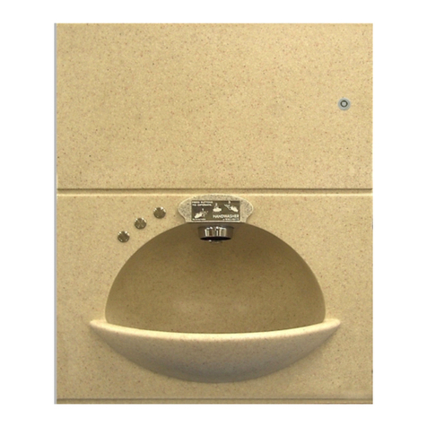
Thrii_SS
Solid Surface
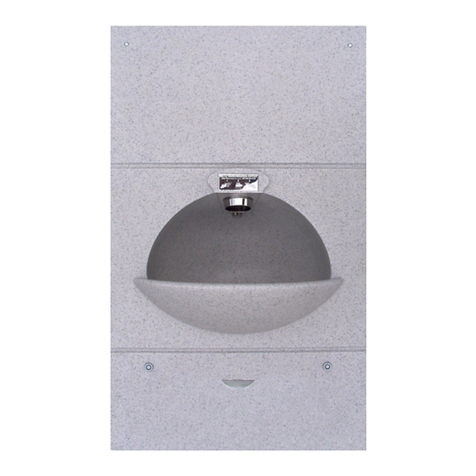
Thrii_DIS_SS
Solid Surface Disabled
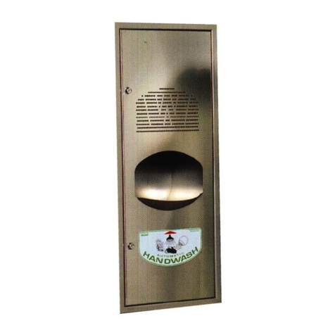
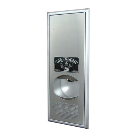
Thrii_ST
Stainless steel
Product Manual

2| P a g e
Wallgate Thrii®
PRODUCT MANUAL Issue 5_3
ORIGINAL INSTRUCTIONS
© 2013 Wallgate Ltd.
Contents
1. Disclaimer& Copyright notice .....................................................................................................3
2. Conventions ................................................................................................................................4
2.1 Warning...............................................................................................................................4
2.2 Caution................................................................................................................................4
2.3 Important ............................................................................................................................4
2.4 Numbered procedures........................................................................................................4
2.5 Bullet lists............................................................................................................................4
2.6 Menu items .........................................................................................................................4
3. Glossary.......................................................................................................................................5
4. Technical Specification................................................................................................................6
5. Overview .....................................................................................................................................7
6. Installation and Commissioning................................................................................................10
6.1 Package Contents..............................................................................................................10
6.2 Site Preparation ................................................................................................................10
6.3 Installing the support frame, water and waste connections and electric ........................11
6.4 Mounting the fascia ..........................................................................................................16
6.5 Engine installation.............................................................................................................18
6.6 Electrical and Water Connections.....................................................................................20
6.7 Commissioning for use......................................................................................................21
7. Programme settings..................................................................................................................23
7.1 Operation ..........................................................................................................................24
7.2 Advanced adjustment .......................................................................................................25
8. Care, Routine maintenance, Service & Repair..........................................................................26
8.1 Care /Cleaning...................................................................................................................26
8.2 Routine maintenance........................................................................................................26
8.3 Service and Repair.............................................................................................................26
8.4 Spare parts ........................................................................................................................27

3| P a g e
Wallgate Thrii®
PRODUCT MANUAL Issue 5_3
ORIGINAL INSTRUCTIONS
© 2013 Wallgate Ltd.
1. Disclaimer& Copyright notice
Every effort has been made to supply information within this manual which is correct. Wallgate
Limited will not be liable for any damage or loss that arises if the person installing, operating or
maintaining the unit has not read or not complied with the manual
In any event, and without prejudice to any warranties in Wallgate Limited’s terms and conditions
of sale, Wallgate Limited’s liability for all damages and losses (including negligence) shall not in
any circumstances exceed the amount paid by the customer for the unit.
Wallgate reserves the right to alter, update or improve its product specification at any time
without prior notice. This manual is specific to the product that it has been supplied with at the
date of supply.
Without prejudice to any warranties in Wallgate Limited’s terms and conditions of sale, any
warranty will be invalidated if the equipment is installed or serviced by unqualified personnel.
No part of this publication and the information contained may be reproduced, transmitted, stored
in a retrieval system, used or disclosed wholly or partly without prior written permission from
Wallgate Limited.
For full warranty details please see Wallgate Limited Terms and Conditions.
Please ensure this manual is passed to the end user. The manual forms an integral part of the
product and should be kept for it's working life. Additional copies of this and other supporting
documents are available by contacting Wallgate Ltd or by visiting www.wallgate.com

4| P a g e
Wallgate Thrii®
PRODUCT MANUAL Issue 5_3
ORIGINAL INSTRUCTIONS
© 2013 Wallgate Ltd.
2. Conventions
Certain conventions are used in this manual to make it easier to read and understand. They are
shown in the sections below.It is recommended that you read and understand these warnings
before you install and commission the Wallgate Thrii.
2.1 Warning
A boxed WARNING! is used to give information about hazards associated with electric current and
high voltages that can cause damage, injury or death. Failure to heed these warnings can have
serious consequences. Example box:
WARNING! The information contained within this ‘Warning’ box indicates hazards associated
with electric current and high voltages
2.2 Caution
A boxed CAUTION! is used to give information about hazards that can cause damage or injury.
Failure to heed these warnings can have serious consequences. Example box:
CAUTION! The information contained within this ‘Caution’ box indicates hazards that require
safety advice for personnel or potential unit/property damage
2.3 Important
A boxed IMPORTANT: is used to draw your attention to important information on installation,
set-up and operation. Example box:
IMPORTANT: The information contained within this ‘Important’ box gives further useful
information.
2.4 Numbered procedures
Steps in procedures are numbered, starting from 1.
1. This is step 1.
2. This is step 2,etc.
2.5 Bullet lists
A bullet list is used to give information that is not necessarily in sequential order.
2.6 Menu items
Menu items, submenu items and settings, where available, are given in bold.

5| P a g e
Wallgate Thrii®
PRODUCT MANUAL Issue 5_3
ORIGINAL INSTRUCTIONS
© 2013 Wallgate Ltd.
3. Glossary
The glossary lists all words, abbreviations and technical terminology used in this manual, along
with a short description of these terms.
Term
Description
Thrii®
Hand Wash Unit
Engine Unit
The Engine Unit refers to the complete soap, water, dryer
module mounted on the back of the fascia.
IR Sensor
The infrared (IR) sensor transmits an invisible beam into the
washbowl area, so that when interrupted by a person's hand
the beam is rebounded back to the receive sensor. This
creates an electrical signal which rapidly activates the hand
wash cycle.
BSP
The British Standard Pipe (BSP) thread is a family of standard
screw thread types that has been adopted internationally for
interconnecting and sealing pipe ends by mating an external
(male) with an internal (female) thread.1
Solid Surface
The term Solid Surface refers to the hard granite-effect or
solid colour material that is moulded to form the Thrii fascia.
Power up
The external electricity supply is provided to the Thrii.
Thrii® is a registered trademark of Wallgate Limited
1Description sourced from Wikipedia at http://en.wikipedia.org/wiki/British_standard_pipe_thread

6| P a g e
Wallgate Thrii®
PRODUCT MANUAL Issue 5_3
ORIGINAL INSTRUCTIONS
© 2013 Wallgate Ltd.
4. Technical Specification
Weight
Item
Fascia
Engine
Support frame, etc.
Full soap container
Total
Solid surface
15.3 kg
7.0 kg
4.5 kg
2.6 kg
29.4 kg
Solid surface
DISABLED
15.3 kg
7.0 kg
4.5 kg
2.6 kg
29.4 kg
Stainless
Steel
7.7 kg
7.0 kg
4.5 kg
2.6 kg
21.8kg
Dimensions
Width
Height
Depth
450mm
870mm
310mm
450mm
793mm
310mm
450mm
870mm
310mm
(250mm behind the panel on all models)
Water Supply
Minimum pressure
Maximum rating
Inlet connection size
Dynamic
1 Bar / 100 kPa
10 Bar / 1000 kPa
15mm Push Fit
(or 1/2” BSP FM adapter)
Electrical Power
requirement
220–240V 50/60Hz, single phase, 2.6 to 3.1 kW
(13 Amp fused double pole switched spur)
Enclosure IP
Rating
IPX4
Regulatory
compliance
Complies with:
RoHS
LVD 2006/95/EC & EMC 2004/108/EC directives.
Solid Surface
Approvals
BS476 Pt 6 Class 0 & 7 Class 1 –fire propagation and surface
spread of flame
ISO EN 19712-3-2007 rated 5 for durability, stain resistance,
cigarette burns, etc.
Water heater
Water temperature range
Factory set @ 38°C
*Based on 12°C supply temperature, 3Bar dynamic
pressure & 230V supply.
30°C to 45°C
Flow rate of 1.5LPM*
Water
Resistivity
Water resistivity must not be less than 1300 Ωcm
(refer EN603355-2)
AS 3498
Certificate No 23167

7| P a g e
Wallgate Thrii®
PRODUCT MANUAL Issue 5_3
ORIGINAL INSTRUCTIONS
© 2013 Wallgate Ltd.
5. Overview
The Wallgate Thrii is an integrated hand wash dryer unit with automatic infra-red sensor
operation. It is available in a solid surface or stainless steel (grade 304) material.
The unitshould only be installed in a frost free environment, to avoid damage.
All models are identical, with the exception of the fascia material & fascia dimensions.
When hands are placed in the centre of the wash bowl, an infra-red sensor activates the hand
washing and drying cycle, supplying soap (liquid or foam), warm water and dryer-air in amounts
and intervals preset as required.
The unit can be installed in a variety of wall types, servicing can be carried out either from the
front (fascia unlocks and whole Thrii swings out) or from within an access duct behind the
machine.

8| P a g e
Wallgate Thrii®
PRODUCT MANUAL Issue 5_3
ORIGINAL INSTRUCTIONS
© 2013 Wallgate Ltd.
Fig. 1 Fascia Front View
Item
No.
Description
Item
No.
Description
1
Fascia
6
IR Sensor
2
Fascia Lock (hidden)
7
Soap Outlet
3
Wash Bowl
8
Water Outlet
4
Dispensing Unit
9
Label (optional)
5
Dryer Outlet

9| P a g e
Wallgate Thrii®
PRODUCT MANUAL Issue 5_3
ORIGINAL INSTRUCTIONS
© 2013 Wallgate Ltd.
Fig.2 Fascia Rear View
Item
No.
Description
Item
No.
Description
1
Fascia
13
Hinge
2
Container Cap
14
Hinge side lock plate
3
Soap Hose
15
Water (inlet) adapter
4
Soap Container
16
Double Check Valve
5
Container Holder
17
Isolation Tap
6
Engine Cover
18
Water Connection (frame)
7
Locking Bar
19
Engine water supply hose
8
Mounting Frame
20
Engine Cover fixing
9
Clamp bracket
21
Control
10
Fascia Lock
22
LCD Control (see fig. 18)
11
Drain
23
Mains Power socket
12
Waste Outlet
24
Soap Selection Knob
10
9
11
12
13
14
8
7
6
5
4
3
2
1
16
15
19
20
17
18
22
21
23
24

10 | P a g e
Wallgate Thrii®
PRODUCT MANUAL Issue 5_3
ORIGINAL INSTRUCTIONS
© 2013 Wallgate Ltd.
6. Installation and Commissioning
The Wallgate Thrii handwash-drier unit is a three-part assemblyconsisting of a flush support frame
and a hinged fascia and engine assembly. It is necessary to install the mounting frame and
prepare the services (electrical, water and waste) prior to installing the fascia.
It is important that when selecting a mounting position consideration be given to the suitability
of the wall construction, so that it is able to bear the weight of the assembled unit in both the
open and closed positions, and able to withstand the clamping method as shown in Fig.6
6.1 Package Contents
Before you begin the installation, make sure that you have the following items:
1 Support frame
1 Installation instructions
1 Wall frame waste connector
1 Waste pipe 32 –40mm adapter pipe
1 Fascia lock key
1 Mains electrical plug and lead (2 metre length)
1 User instruction label
1 Set of mounting brackets and fixings
1 Fascia
1 Engine
1 Container of liquid soap (2.5 litre)
6.2 Site Preparation
6.2.1 Mounting guidelines
Looking at the front of the unit the fascia hinges are on the right-hand side. For front access
allow for the left-hand edge of fascia to swing out (120°) to allow full internal access.
Water, mains power andwaste water connections are located on the hinged side of the unit.

11 | P a g e
Wallgate Thrii®
PRODUCT MANUAL Issue 5_3
ORIGINAL INSTRUCTIONS
© 2013 Wallgate Ltd.
Make an opening in the wall surface according to the dimensions shown in drawing Fig.4 noting
the appropriate mounting height as detailed on the drawing table A.
The opening must be according to the dimensions given in fig.4. The aperture must be accurate
in order for the door mechanism to work effectively.
The unit will be fitted to the support frame supplied. The frame is fixed to the sides of the wall
opening using the frame fixing brackets provided. The front edge of the frame must be flush
with the finished face of the wall. On IPS panel walls such as trespa or corian the aperture in the
panel should be lined on the rear face with 50mm timber studding.
Complete all surface finishes such as screed, plaster or tiling before attaching the fascia to the
support frame.
All electrical work must be carried out by a qualified electrician and should be installed in
accordance with the current Nationally Approved Regulation
The installer must:
Provide an electrical supply of 220–240V 50/60Hz with a switched fused spur. The fused spur
must be a 13Amp, double pole connection point that is local to the unit (the contact separation of
the fused spur switch should be at least 3mm). Earth bonding for this type of unit must comply
with the nationally approved regulations.
The switched fused spur MUST be accessible from either the front of the Thrii or from the rear
without having to open the fascia
Provide a mains cold water supply mounted behind the wall below the ‘hinge’ side of the
aperture. Terminate the cold water supply with a suitable isolating tap. For optimum operation a
dynamic water flow pressure of between 1 & 3 bar is required.
Request advice from Wallgate before you connect the unit to a gravity-fed water supply.
Provide a waste pipe with suitable deep seal waste trap for connection of 32mm (1¼”) or 40mm
(1 ½”) behind the wall below the ‘hinge’ side of the aperture.
6.3 Installing the support frame, water and waste connections and electric
1. Remove the support frame from the packing box.
2. Orientate the frame with hinge plates on the right-hand side and waste outlet parts at bottom
and facing away from you. The frame front edge should now be facing towards you.

12 | P a g e
Wallgate Thrii®
PRODUCT MANUAL Issue 5_3
ORIGINAL INSTRUCTIONS
© 2013 Wallgate Ltd.
3. Place the frame into the front of the aperture, ensuring it is flush fitting with the finished face of
the wall, at the correct height and perfectly level in the horizontal and vertical planes.The hinge-
side of the frame should be hard up against the aperture.
Fig.4 Typical site preparation for Wallgate Thrii unit. (Dimensions in millimetres)
Note hinge positions on the right-hand side when looking from the front
427 Aperture Width
+ 5
- 0
683 Aperture Height
+ 5
- 0
800 **
** Other mounting heights:
For Disabled model Thrii_DIS_SS:
UK = 590mm
France = 700mm
Australia = 680mm
New Zealand = 675mm
Finished
Floor Level

13 | P a g e
Wallgate Thrii®
PRODUCT MANUAL Issue 5_3
ORIGINAL INSTRUCTIONS
© 2013 Wallgate Ltd.
Refer to table below
Rear View Side View
Fig.5 Fascia Dimensions (in millimetres)
Model
Fascia height dimension
Thrii_SS
870mm
Thrii_DIS
793mm
Thrii_ST
870mm

14 | P a g e
Wallgate Thrii®
PRODUCT MANUAL Issue 5_3
ORIGINAL INSTRUCTIONS
© 2013 Wallgate Ltd.
Fig.6 Typical site installation of Wallgate Thrii unit showing clamping bracket (view on rear)
2 –3 mm
The switched
fused spur MUST
be accessible from either
the front of the Thrii or
from the rear without
having to open the fascia

15 | P a g e
Wallgate Thrii®
PRODUCT MANUAL Issue 5_3
ORIGINAL INSTRUCTIONS
© 2013 Wallgate Ltd.
4. Insert the 4No. M10x150mm threaded rods through the corner angles on the support frame and
into the brackets as shown in Fig. 6
5. Tighten all 4 brackets until the wall frame is held securely in place in the wall opening. It is
important that the frame side members are not distorted when tightening to the wall, as this may
prevent the hinge and catch mechanisms from working properly.
6. Once the frame is securely attached to the wall, if necessary make good any excessive gaps
between the frame and the wall that may not be covered by the fascia.
7. Install the waste connector to the frame as shown in Fig. 7 (below) along with the pipe adapter
which then terminated to the deep seal waste trap as detailed in section 6.2 site preparation.
Note that the pipe adapter can be used for either a 32mm or 40mm pipe connection.
Fig.7 Waste fitting assembly (view on rear)
8. Provide a cold water supply pipe to connect to the inlet connector on the support frame see Fig.2
& 6. Note that the water inlet connector can be altered to be either 15mm push fit or ½” BSP FM.
The ½” BSP FM brass adapter fitted to the inlet can be removed to alternatively use the 15mm
push fit connection.
The hand wash unit is supplied with a double check valve fitted to the water inlet connection
which must be in place to comply with water regulations.
If pipe sealing compound is used, avoid applying excessive amounts as particles of sealant can
block water filters and impede valve operation.
Before completing the water supply connection to the unit, flush the mains water supply pipes
to remove any debris and trapped air. Failure to do so may result in damage and failure of the
unit.
9. Connect the supplied electrical cable to the 13 amp spur connection unit.
Ø32mm
Ø40mm
Ø40mm

16 | P a g e
Wallgate Thrii®
PRODUCT MANUAL Issue 5_3
ORIGINAL INSTRUCTIONS
© 2013 Wallgate Ltd.
6.4 Mounting the fascia
Ensure that the fascia is fully supported until both hinges are fully engaged. Failure to do so may
damage the hinges
For ease of installation it is recommended to have at least two people carry out this operation
1. Remove the fascia from the packing box.
2. With the right-hand side of the fascia vertically aligned with the support frame and offered up in
the ‘open’ position (approximately 120°), extend the fascia hinges to the open position, align
andlocate hinge ends into the hinge side lock plates on the support frame and engage the two
parts to secure the two halves together. See Fig. 8
Fig.8 Hinge assembly Fig. 9 Hinge release spigot detail
3. Engage the ‘Hinge release lock’ spigot, fitted to each hinge to prevent accidental hinge latch
release see Fig.9
4. It is necessary to check the fascia alignment with the frame before proceeding further, as the
hinges may need adjustment. Carefully close the fasciaensuring the door opens and closes freely.
In the closed position, visually check the gap between the fascia and the wall along the hinged
edge, and adjust the hinges as appropriate to ensure an even fit using the adjustment screw on
the hinges see Fig. 10a. Do not over-tighten as this may result in the fascia damaging the wall
finish. Horizontal adjustment of the fascia door can be configured, (see Fig. 10b) however note
this is factory set.

17 | P a g e
Wallgate Thrii®
PRODUCT MANUAL Issue 5_3
ORIGINAL INSTRUCTIONS
© 2013 Wallgate Ltd.
(a)
(b)
(a)
(b)
Fig.10 Hinge adjustment. 10a showing depth adjustment. 10b showing side adjustment
Note hinge release spigot in place
5. Once the fit has been checked, close the fascia fully to check the locking bar operation. The
locking bar is spring-loaded and may require a firm push to engage correctly. To re-open insert
the key provided into the fascia lock release at the base of the fascia, ¼ turn anti-clockwise and
push the key up to disengage the lock and allow the fascia to open freely see Fig. 2.
6. For installations where front access is not required in addition to the hinge release lock, engage
the 2 hinge side locks, rotating into the slot provided in the frame as shown in
Fig. 11a, and when the lock bar has been fully engaged, relocate the top screw fixing into the
locking position below, as shown inFig. 11b
Fig.11 Securing the unit for rear-access only, 11a showing hinge side locks, 11b showing fixing
repositioning

18 | P a g e
Wallgate Thrii®
PRODUCT MANUAL Issue 5_3
ORIGINAL INSTRUCTIONS
© 2013 Wallgate Ltd.
6.5 Engine installation
1. Remove the engine cover, retaining the engine cover fixing.
2. Remove the securing pin out through the side from the base of the engine Fig. 12
Fig.12 Securing pin removal Fig. 13 Fitting the engine
3. Present the engine to the engine mounting plate on the back of the fascia locating the dispensing
nozzle into the aperture provided. Align the engine on the plate and click into place Fig. 13
4. Replace the securing pin through both mounting plates and engine ensuring it passes fully
through this assembly Fig. 14
Fig.14 Fitting the securing pin

19 | P a g e
Wallgate Thrii®
PRODUCT MANUAL Issue 5_3
ORIGINAL INSTRUCTIONS
© 2013 Wallgate Ltd.
5. Replace the engine cover, ensuring the flexible hose and soap hose attached does not foul upon
reassembly, and secure the cover into place with the fixing provided Fig. 15
Fig.15 Replacing the engine cover

20 | P a g e
Wallgate Thrii®
PRODUCT MANUAL Issue 5_3
ORIGINAL INSTRUCTIONS
© 2013 Wallgate Ltd.
6.6 Electrical and Water Connections
From the rear side of the wall:
6.6.1 Electrical connection from the wall mounted fused spur switch to the Thrii:
All electrical work must be carried out by a qualified electrician and should be installed in
accordance with the current Nationally Approved Regulations
Complete the electrical connection by fitting the plug into the socket on the rear of the engine.
Ensure the cable is a suitable length so that the door can fully open without catching or fouling.
6.6.2 Mains water connection from support frame to the engine:
Using the flexible water hose provided take the loose end of the hose, which is attached to the
engine, and attach it to the water inlet connection mounted on the upper bracket part of the
support frame See Fig. 16. With all services connected to the Thrii, open and close the fascia
assembly to ensure that the wiring and piping feeds move without snagging or kinking. Ensure
the waste spigot from the wash bowl smoothly engages with waste outlet on the frame bracket.
Fig.16 Engine water supply hose connection to water connector on wall frame
Push-fit hose connector
with twist-lock collar
Flexible hose
Double check valve
Ø15mm Connector
½“ BSP FM Adapter (Optional - UK)
Cold Water Supply
This manual suits for next models
2
Table of contents
Other Wallgate Dryer manuals