Wasp WWS150i User manual

WWS150i

Table of Contents
Chapter 1 Introduction 2
Chapter 2 Barcode Symbologies 3
Chapter 3 Quick Start 4
Chapter 4 WWS150i Setup & Configuration 6
1. Setup & Configuration 6
2. Factory Default and Autosense Stand Mode 6
3. Connection and Scan Options 7
4. Start and Stop Pin 8
5. Interface Settings 9
6. Memory Mode 10-12
7. Beep Settings 13
8. iOS Hotkey 14
9. Set Scanner 1D 15
10. Beep Delay and Caps Lock 16
11. Language and Preamble/Postamble 17
12. Terminator/Code ID 18
13. Enable/Disable Barcode Symbologies 19
Code 39 and Interleaved 2 of 5 Settings 20
Code 93 and MSI Plessey Settings 21
Code 128 and UCC/EAN 128 Settings 22
Codabar and UPC-A Settings 23
UPC-A Supplement Settings / UPC-A to EAN-13/UPC-E Settings 24
UPC-E Supplement/EAN-8 Settings 25
EAN-8 Supplemental and EAN-13 Settings 26
EAN-13 Supplemental Settings 27
Chapter 5 Bluetooth Settings 28
Appendix A Barcode Test Symbols 29-30
Appendix B ASCII Table 31-34
Appendix C Function Codes for PC 35
Appendix D Technical Specifications 36
Appendix E Warranty Information 37
FAQ 38
Product Support 39

2
Chapter 1
2
Introduction
Barcoding is the most common Automated Data Collection (ADC) technology. It provides timely, error-free information that
can be used to increase productivity, accuracy, and efficiency in the workplace. Virtually every type of industry is using
barcodes to replace keyboard data entry. Studies have shown that a proficient data entry operator will make one error for every
300 characters that are manually entered. The error rate using barcodes is negligible and can be error-free using barcode
symbologies with the check digit enabled.
The Wasp Charged Coupled Device (CCD) technology is a technique whereby a barcode is photographed, digitized, and
electronically sampled by built-in photodetectors. The detectors process the measurement of every bar and space using the
number of adjacent photodetectors which contrast a black mark and a white space. Of all the hand-held barcode scanning
devices on the market, the CCD reader is the easiest to use and most cost effective for the typical business user.
The Wasp WWS150i Scanner is an extended distance scanner with a depth of reading of up to one foot depending on the mil size
of the barcode. To activate the scanner, the user simply points the scanning aperture towards the barcode, pulls the trigger, and
aims the red LED beam across the barcode.

2
Chapter 2
3
Barcodes are symbols consisting of a series of bars and spaces which can be applied to packages, cartons, bottles, and other
commercial products. The bars and spaces in each symbol are grouped in such a way to represent a specific ASCII character
or function. The interpretation of these groups is based on a particular set of rules called symbologies. Various symbologies
have been developed for particular applications. Some examples are shipping and receiving, manufacturing, retail, healthcare,
transportation, document processing and tracking, and libraries.
The resolution of a barcode is dependent on the narrowest element of a barcode (X dimension), and can vary from high density
(nominally less than 0.009 in./0.23 mm), medium density (between 0.009 in./0.23 mm and 0.020 in./0.50 mm), and low density
(greater than 0.020 in./0.50 mm). Medium and low densities are the most common since these are the easiest to read (scan)
with nearly all scanning devices. The Wasp WWS150i scanner can read barcodes with X-dimensions as low as 5 mils (0.005
in/0.13mm).
The Wasp WWS150i Scanner can read the most popular barcode symbologies including Code 39, Code 93, Code 128, Interleaved
2 of 5, UPC-A, UPC-E, EAN/JAN-8, EAN/JAN-13, Codabar, and MSI/Plessey.
Please see test chart on pages 26-27.
Barcode Symbologies

4
Chapter 3 QUICK START
Quick Start
1. Unpack.
Open the box and remove all the pieces from their protective packaging.
2. Charging the WWS150i.
You must charge the scanner for 4 hours before first using it. To charge the
scanner plug the power supply in to the bottom of the scanner.
3. Setting up Bluetooth.
If you already have Bluetooth setup on your PC or device, please continue
to the next step.
To setup Bluetooth on your PC you will need to insert the CD with the Bluetooth software on it. Follow the instruction on the CD
for installing the Bluetooth software.
4. Connecting the scanner to a Bluetooth device.
The scanner will connect to most Bluetooth devices that support HID connection.
You will need to open your Bluetooth software and search for Bluetooth devices. The Bluetooth software can be found by clicking
the Bluetooth symbol on the start bar near the computer time. If the Bluetooth symbol is
not found, there could be a problem
with the Bluetooth installation.
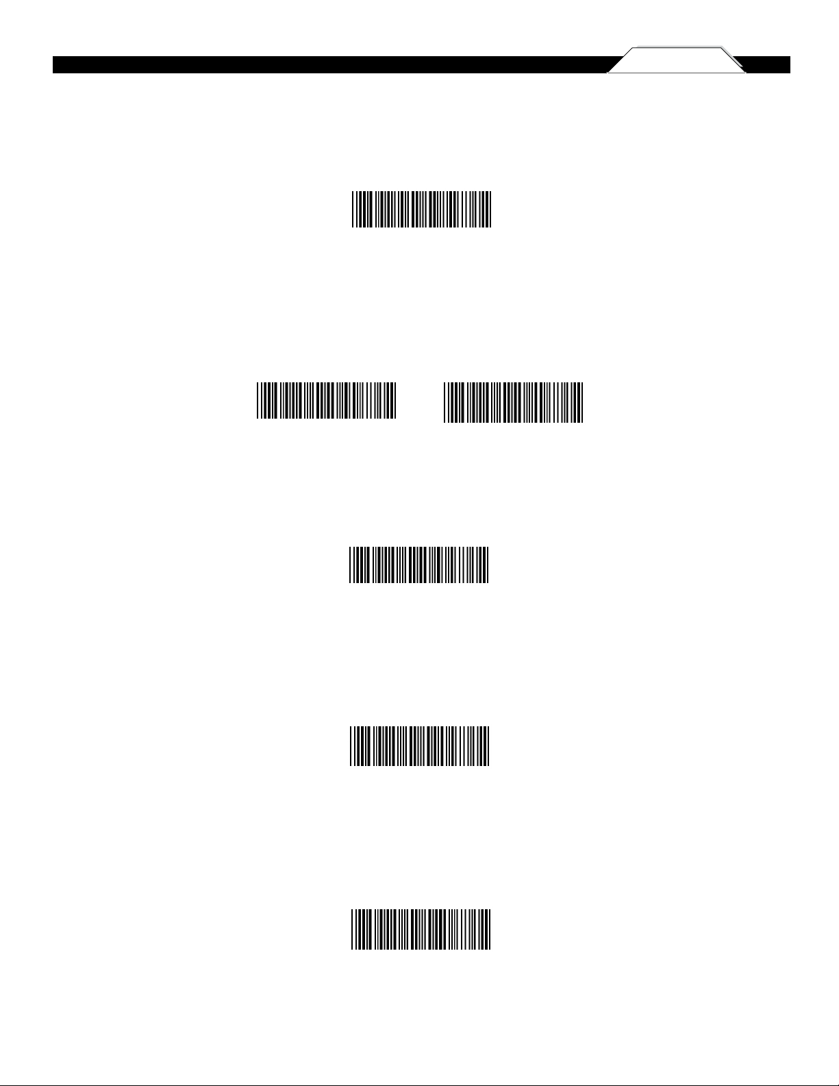
Once you have the Bluetooth software open you will need to scan the Set Connection
barcode (pg 7). This will make the scanner
ready
to be detected by the Bluetooth software.
The following screens are Microsoft’s standard Bluetooth wizard.
*Most Bluetooth wizards will have similar steps. Instructions for XP users are displayed below. Instructions for Win7 users
begin on page 5
Check the “My device is setup and ready to be found.” and click Next.
The scanner will show up in the list of Bluetooth devices found. Select the Wasp Barcode Bluetooth
Keyboard and click Next.
If Wasp Barcode Bluetooth Keyboard does not show up in the available devices please check the
following:
1. Make sure the scanner is on by pressing the trigger.
2. If you are using a pre-installed Bluetooth
adapter, make sure the adapter supports HID.
The next step will ask you to setup a passkey for the device. By default the scanner will not have a
passkey set. Please select “Don’t use a passkey” and click Next.
You can set a passkey later if you prefer,see Start/Stop Pin on page 8 for details.

4
Chapter 3
5
LED Light Indicator
Scan/Wake Scanner (After Idle)
Toggle Keyboard On/Off & Connect Via BT
Cable/Charge Port
The Complete Wizard screen appears. Just click Finish to complete.
Once the wizard is complete the scanner will show up as a Wasp Keyboard. Click OK to close the
screen. You are now ready to use the WWS150i.
(XP Instructions, cont.)
Win7 Instructions
On the Add a Device screen, select Wasp Barcode. Click the Next button.
Enter the Pairing Code provided into your mobile device. Once the PC detects the pairing code
has been entered and a connection has been established, the Next button will become enabled.
Click
Next to contine.
You can verify that your device has been added by clicking the Devices and Printers link on the
screen. Click Close to close the connection wizard.
QUICK START

6
Chapter 4
6
SETUP AND CONFIGURATION/FACTORY DEFAULT/AUTOSENSE STAND MODE
Use the Factory Default barcode to reset the scanner to the Default settings.
Factory Default
Autosense Flash Mode Enable
Scan this Autosense Stand Mode barcode to enable the hands-free autosense feature of the WWS150i Scanner. If you desire to turn this mode “off,”
please scan the default barcode above.
Autosense Stand Mode
In order to configure the Wasp WWS150i Scanner, you must familiarize yourself with the setup procedures on the following pages.
The default settings of the scanners are identified on each page and clearly marked using an asterisk (*). The default settings have
been preprogrammed for the most common barcode configurations. Use the setup & configuration barcodes only to customize the
WWS150i Scanner settings. If you need to configure the Scanner, the default settings will be overwritten. All the programmed settings
are stored permanently in non-volatile memory.
In order to configure the Wasp WWS150i Scanner, two basic steps need to be followed:
(1) Locate the group that contains the options to be changed.
(2) Scan the barcode representing the option to be changed. The scanner will sound two beeps.
To change Minimum/Maximum Length:
(1) Scan the Minimum or Maximum Length barcode associated with the symbology.
(2) Scan a 2 digit value from the ASCII table on pages 28-31.
(3) Scan the Minimum or Maximum Length barcode again.
Example: To have a minimum length barcode of 1, you must scan a 0 then 1, then scan the minimum barcode again. To have a
maximum length barcode of 10, you must scan a 1 then 0, then scan the maximum barcode again.
Setup & Configuration
Factory Default
Note: Enabling this option will significantly increase the WWS150i Scanners battery consumption.

6
Chapter 4
7
CONNECTION AND SCAN OPTIONS
Check Version
Scan the Check Version barcode to verify your current firmware’s version number.
Check Version
The Link Quality affects the transmission quality. When Link Quality is turned on (default setting), data transfer is more secure, but
slower. If you notice that your transmissions to the host are too slow, you can try turning the Link Quality setting to off.
Link Quality On/Off
Link Quality On Link Quality Off
Set Connection
Scan this barcode to break your current connection and enable your device to connect to a new Bluetooth host.
Set Connection
Bluetooth SPP (Bluetooth COM)
The Bluetooth SPP (Serial Port Protocol) creates a virtual Bluetooth comport. This setting is not recommended. Only use this option if
you have software capable of capturing data off of a comport.
Bluetooth SPP (Bluetooth COM)
Bluetooth HID
Use this setting (on by default) to pair with most Bluetooth connections. Bluetooth HID works just like a keyboard..
Bluetooth HID

8
Chapter 4
8
CONNECTION AND SCAN OPTIONS
9
Start and Stop Pin
Use the Start and Stop Pin barcodes when you are prompted for a password during Bluetooth pairing. To use this setting:
1. When prompted for a password, scan the Start Pin barcode
2. Scan the appropriate numbers (provided below) for your password.
3. Scan ENTER.
4. Scan the Stop Pin barcode.
Now the Pin is set and the scanner should pair to the PC. Test the connection by scanning a barcode from WordPad, NotePad or the
equivalent and verifying the scan is correct.
Start Pin Stop Pin
ENTER
Scan the numbers for your password, then scan ENTER.

8
Chapter 4
INTERFACE SETTINGS
9
Scan any one of the barcodes below to reset the scanner back to the desired interface:
*To retrieve stored data, connect the scanner to the host with the cable, access removable storage device “Miniscan” from which you may open or
copy the file “Barcode.txt” to your computer.
To exit memory mode, scan any interface barcode in the “interface” section of the manual.
*

10
Chapter 4
INTERFACE SETTINGS AND MEMORY MODE
Memory Mode
Interface Settings
Delete Last Record
After scanning the above barcode, the scanner will be able to collect barcode data off-line. The barcode data will be stored in the format
of: < Date >, < Time >, < Barcode Data > < CR > (see below to change formats)
To retrieve stored data, please connect the scanner to the host with cable.
Access removable storage device “MiniScan” from which you may open or copy the file “BARCODE.txt” to your computer.
To delete ONE stored data, please scan below barcode or press Delete Button.
To delete ALL stored data, simply delete the file “BARCODE.txt” in the removable storage device “MiniScan” until you hear two beeps.
To exit memory mode, scan any interface barcode in the “interface” section of the manual.
Scan any one of the barcodes below to reset the scanner back to the desired interface:
*
After scanning the above barcode, the scanner will be able to collect barcode
data off-line. The barcode data will be stored in the format of:
< Date >, < Time >, < Barcode Data > < CR >
To retrieve stored data, please connect the scanner to the host with cable,
access removable storage device “MiniScan” from which you may open
or copy the file “BARCODE.txt” to your computer.
To delete ONE stored data, please scan below barcode or press Delete Button.
To delete ALL stored data, simply delete the file “BARCODE.txt” in the
removable storage device “MiniScan” until you hear two beeps.
. R005$
*.R005$*
MEMORY MODE
- 25 - - 26 -
TERMINATOR
LF
CR + LF
NONE
SPACE
TAB
. D012$
CR
. D011$
. D013$
. D010$
. D015$
. D014$
. C035$
*.c035$*
Memory Mode
Delete Last Record
Delete Button
WIRELESS SCANNER SETTINGS
GROUP-13
Emulates a USB virtual com device that transmit each
barcode data to the host after decode. Barcode data is
sent via USB cable directly. For VCP driver, please contact
our sales representative or technical support team.
. C006$
USB VCP
. C008$
USB HID
INTERFACE
BT SPP
. E042$
. E043$
Memory Mode
. C035$
Emulates a Bluetooth HID keyboard that transmits
each barcode data to the host after decode. Wireless
scanner operates in this mode right out of box. Please
see next page for details.
Emulates a USB keyboard that transmits each barcode
data to the host after decode. Barcode data is sent via
USB cable directly.
Emulates a USB mass storage device that saves each
barcode data during off-line data collection. See Memory
Mode chapter (Group 23) for details.
Emulates a Bluetooth SPP device that transmits each
barcode data in serial communication to the host
after decode. Please see next page for details.
BT HID

10 11
Chapter 4
MEMORY MODE MEMORY MODE
Example: To set Date to 2014-08-01 (Year-Month-Day):
1. Scan [
Set Date
]
2. Scan [1], [4], [0], [8], [0], [1] on page 11 & 12.
3. Scan [
Set Date
]
Example: To set Time to 08:10:30 am (Hr:Min:Sec)
1. Scan [
Set Time
]
2. Scan [0], [8], [1], [0], [3], [0] on page 11 & 12.
3. Scan [
Set Time
]
. R006$
*.R006$*
SET DATE
. R007$
*.R007$*
SET TIME
* To avoid Time and Date being reset to factory default due
to running out of battery, please fully charge the scanner for
at least 3 hours before use.
- 27 - - 28 -
Example:
To change Data Format to
<Barcode Data>, <Date>, <Time>
1. Scan [
Data Format
]
2. Scan [4], [2], [3] on page 11.
3. Scan [
Data Format
]
The default Data Format is
<Date>, <Time>, <Barcode Data>
below are the codes for each item:
. R011$
*.R011$*
DATA FORMAT
2
4
Date
Barcode Data
Code Item Code Item
3 Time
Memory Mode
Example: To set Date to 2014-08-01 (Year-Month-Day):
1. Scan [Set Date]
2. Scan [1], [4], [0], [8], [0], [1] on page 10. (yymmdd)
3. Scan [Set Date]
Example: To set Time to 08:10:30 am (Hr:Min:Sec)
1. Scan [Set Time]
2. Scan [0], [8], [1], [0], [3], [0] on page 10. (hhmmss)
3. Scan [Set Time]
* To avoid Time and Date being reset to factory default due to running out of battery, please fully charge the scanner for at least 3 hours before use.
The default Data Format is <Date>, <Time>, <Barcode Data>. Below are the codes for each item:
Code Item
2 Date
3 Time
4 Barcode Data
Example:
To change Data Format to <Barcode Data>, <Date>, <Time>
1. Scan [Data Format]
2. Scan [4], [2], [3] on page 10.
3. Scan [Data Format]
MEMORY MODE

12
Chapter 4
The default Date Format is DD/MM/YYYY (Code = 09). Below is full list of available formats and their setup codes:
Code Format
01 DD-MM-YYYY
02 MM-DD-YYYY
03 DD-MM-YY
04 MM-DD-YY
05 YYYY-MM-DD
06 YY-MM-DD
07 DD-MM
08 MM-DD
09 DD/MM/YYYY
10 MM/DD/YYYY
11 DD/MM/YY
12 MM/DD/YY
13 YYYY/MM/DD
14 YY/MM/DD
15 DD/MM
16 MM/DD
Example:
To set Date Format to MM/DD/YY (Code =12)
1. Scan [Date Format]
2. Scan [1], [2] on page 11.
3. Scan [Date Format]
The default Time Format is HH:MM:SS (Code = 01). Below are available formats and their setup codes:
Code Format
01 HH:MM:SS
02 HH:MM
Example:
To set Time Format to HH:MM (Code = 02)
1. Scan [Time Format]
2. Scan [0], [2] on page 11 & 12.
3. Scan [TimeFormat]
The default Date Format is DD/MM/YYYY (Code = 09), below
is full list of available formats and their setup codes:
Example:
To set Date Format to MM/DD/YY (Code =12)
1. Scan [
Date Format
]
2. Scan [1], [2] on page 11.
3. Scan [
Date Format
]
. R008$
*.R008$*
DATE FORMAT
MEMORY MODE
01
02
03
04
05
06
07
08
DD-MM-YYYY
MM-DD-YYYY
DD-MM-YY
MM-DD-YY
YYYY-MM-DD
YY-MM-DD
DD-MM
MM-DD
Code Format Code Format
09
10
11
12
13
14
15
16
DD/MM/YYYY
MM/DD/YYYY
DD/MM/YY
MM/DD/YY
YYYY/MM/DD
YY/MM/DD
DD/MM
MM/DD
The default Time Format is HH:MM:SS (Code = 01), below
are available formats and their setup codes:
Example:
To set Time Format to HH:MM (Code = 02)
1. Scan [
Time Format
]
2. Scan [0], [2] on page 11 & 12.
3. Scan [
TimeFormat
]
. R009$
*.R009$*
TIME FORMAT
MEMORY MODE
01 HH:MM:SS
Code Format Code Format
02 HH:MM
- 29 - - 30 -
MEMORY MODE

13
The ‘Beep and Delay’ configuration supports the general control options for the Wasp WWS150i Scanner. These options include the volume,
intercharacter delay, and interblock delay.
Interblock delay (see page 13) is the minimum time interval between two adjacent scans. If the processing speed of your host device is slower than
your scanning speed, a longer interblock delay may ensure the data integrity.
Intercharacter delay (see page 13) is the time period that the scanner will wait before transmitting the next character. If data sent by the scanner has
incorrect or missing characters, a longer intercharacter delay may solve the problem. The intercharacter delay should be changed only if the transfer
rate cannot be maintained between the scanner and the keyboard buffer of the computer.
Note: The default for the intercharacter delay is set to ‘140us’ and is the most common configuration; however, your PC may be different. When you
scan a barcode, if some stray or scrambled characters appear, increase the intercharacter delay to slow down the transfer rate.
Beep Off
Beep High Beep High--Low
Beep Medium Beep Low--High
Beep Settings
WWS150i
Beep Low
Chapter 4 BEEP SETTINGS

13 14
Use these barcodes to enable or disable the iOS hotkey on your device.
*Default
Enable/Disable iOS Hotkey
Enable iOS Hotkey
Disable iOS Hotkey *
Chapter 4
ENABLE IOS HOTKEY/SECURE SIMPLE PAIRING

15
Chapter 4 SET SCANNER ID
Setting the scanner ID allows you to give each scanner a unique name. This unique name identifies it if you have more than one scanner in the
area.
Set Scanner ID procedure:
1. Clear Scanner ID
2. Set Scanner ID
3. Scan up to 16 characters from the ASCII table on pp 28-31.
4. Set Scanner ID
5. Bluetooth HID
Note: Sometimes only 8 characters of a longer name are seen when pairing, e.g. “Wasp Bar” instead of “Wasp Barcode”.
Clear Scanner ID procedure:
1. Clear Scanner ID
2. Bluetooth HID
Note: WWS150i & WWS550i: name defaults to “Wasp Barcode”.
For the scanner to transmit a new name, it may need to be unpaired. When the new name is seen, set the power-off time back to a longer value.
*Default
Set Scanner ID
Step 1 - Default Wireless ID
Step 2 - Set Wireless ID
Step 4 - Set Wireless ID
Step 3 - Scan up to 16 alphanumeric
characters from Full ASCII Table as your
desired ID name.

15 16
Chapter 4
INTERBLOCK/INTERCHARACTER DELAY AND CAPS LOCK
0ms * 10ms 50ms
100ms 200ms
140us * 500us 1ms
4ms 16ms
500ms
Interblock Delay
Intercharacter Delay
*Default
• Caps Lock Auto (For PC XT/AT only):
In Auto mode, the scanner will keep track of the Caps Lock status automatically. For some PCs, the scanning performance may be
compromised because of the auto tracing. If the scanning performance is poor (or cannot scan) or the scanner cannot output the
upper/lower case characters correctly, try to select one of the next two choices instead of auto tracing.
• Caps Lock Off:
When the keyboard is in the unshifted state
(Caps Lock is not pressed), select “Lower Case.”
• Caps Lock On:
When the keyboard is in the shifted state (Caps Lock is on),
select “Upper Case.”
Caps Lock On
Caps Lock Off *
Caps Lock Auto

17
Chapter 4
17
KEYBOARDLANGUAGE AND PREAMBLE/POSTAMBLE
U.S. * German
French Spanish
Italian
The ‘Keyboard Language’ setting controls the key codes for your keyboard’s language.
The ‘Preamble/Postamble’ configuration is used to add a prefix or suffix set of characters to the barcode value. Up to 8 characters
may be added for each option separately. Preamble and postamble characters can function concurrently, but need to be configured
separately.
To add preamble or postamble characters, follow the steps below:
1) Scan the ‘Clear Pre/Postamble’ barcode on this page.
2) Scan the ‘Preamble’ or ‘Postamble’ barcode.
3) Use Appendix B on pages 28-31 to locate the characters you want to add as preamble or postamble characters. Make sure
that you scan the barcode associated with each letter before preceding to the next character. For example, to add the
letter “A,” scan the barcode corresponding to the letter “A”. The letter “A” will always appear in your data as prefix or suffix
to the barcode value.
4) Scan the corresponding ‘Pre/Postamble’ barcode on this page to exit this setting.
Clear Pre/Postamble Preamble
Postamble
*Default

17
Chapter 4
TERMINATOR/CODE ID
17 18
O - MSI/Plessey T - EAN 128
S - EAN 8 K - Code 128
E - UPC E N - Codabar
A - UPC A D - Full ASCII Code 39
F - EAN 13 M - Std. Code 39
L - Code 93 I - Interleaved 2 of 5
Terminator
CR *
None
Code ID
Code ID On
Code ID Off *
LF
CR + LF
Tab
Space
ESC
The ‘Terminator’ option is used to specify the end-of-text message and is primarily used to denote the end of the barcode value.
The ‘Code ID’ option sends a specific value when a particular barcode symbology is scanned. For example, if ‘Code ID’ is enabled and
Code 39 is scanned, an “M” will appear in the data stream in front of the barcode value.
*Default

19
Chapter 4 ENABLE/DISABLE BARCODE SYMBOLOGIES
Enable Disable
Enable All
MSI Plessey
Interleaved 2 of 5 *
Code 128 *
Codabar *
Code 39 *
Disable All
MSI Plessey *
Interleaved 2 of 5
Code 128
Codabar
Code 39
UPC A *
UPC E *
EAN 8 *
EAN 13 *
Code 93
UPC A
UPC E
EAN 8
EAN 13
Code 93 *
*Default
Other manuals for WWS150i
1
Table of contents
Other Wasp Barcode Reader manuals

Wasp
Wasp WDT 3200 Installation and operation manual

Wasp
Wasp 2D User manual

Wasp
Wasp HC1 User manual

Wasp
Wasp WLR8900 Operating instructions

Wasp
Wasp WLR8950 User manual

Wasp
Wasp 2D User manual

Wasp
Wasp WPL205 User manual

Wasp
Wasp WWS110i User manual

Wasp
Wasp WPL618 Series User manual

Wasp
Wasp WWS800 User manual

Wasp
Wasp WLS9600 Installation and operation manual

Wasp
Wasp WDI9600 User manual

Wasp
Wasp WDI4700 User manual

Wasp
Wasp WPA 1200 II User manual

Wasp
Wasp WLS9600 User manual

Wasp
Wasp WLS 9500 User manual

Wasp
Wasp WPL304 User manual

Wasp
Wasp Bar Code Laser Operating instructions

Wasp
Wasp WWS650 User manual

Wasp
Wasp WWS800 User manual