Waycon UFA-CP Series User manual

INSTALLATION GUIDE
Ultrasonic Sensor Series UFA2, UFA-CP and UFA-6000
For further information please see the data sheet at www.waycon.biz/products/ultrasonic-sensors/
FIRST STEPS
WayCon Positionsmesstechnik GmbH would like to thank you for the trust you have placed in us and
our products. This manual will make you familiar with the installation and operation of our ultrasonic
sensors. Please read this manual carefully before initial operation!
Unpacking and checking:
Carefully lift the device out of the box by grabbing the housing. After unpacking the device, check
it for any visible damage as a result of rough handling during the shipment. Check the delivery for
completeness. If necessary consult the transportation company, or contact WayCon directly.
SAFETY NOTICES
• These products are neither allowed to be used as safety- or emergency shut-o devices, nor in other
applications, where a malfunction of this product may result in personal injury.
• Failure to follow this notice may result in serious or fatal injury.
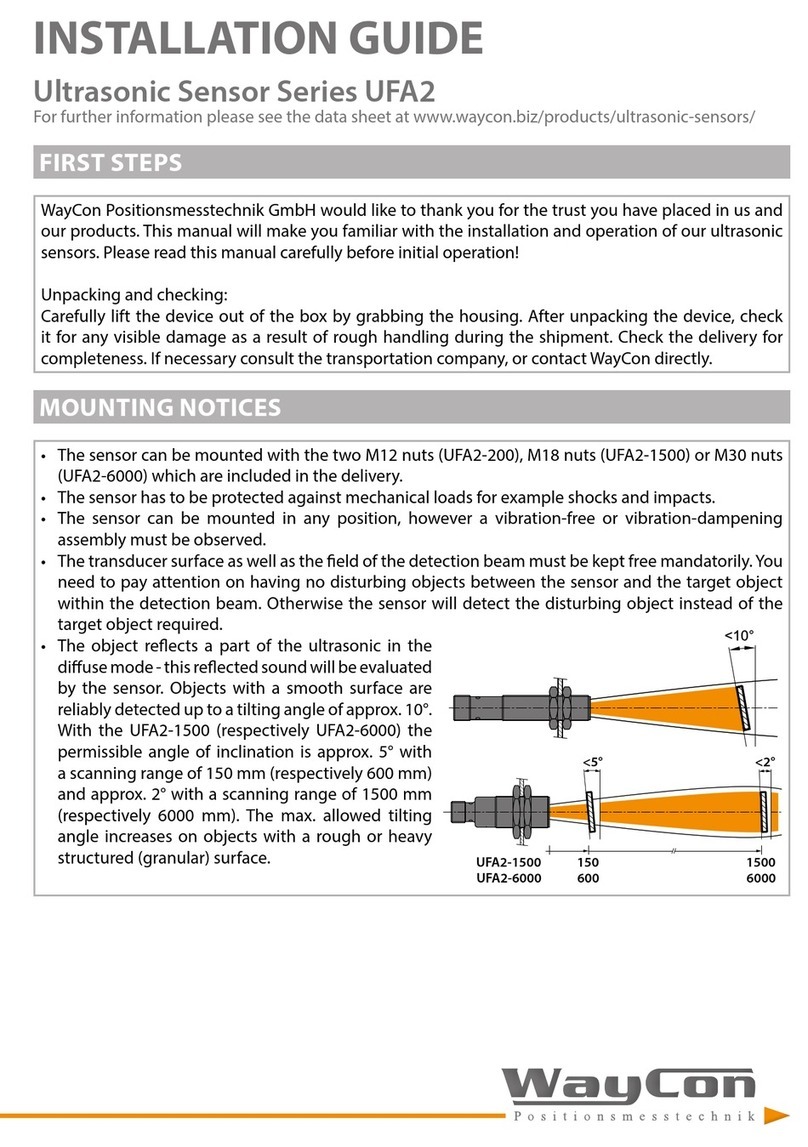
MOUNTING NOTICES
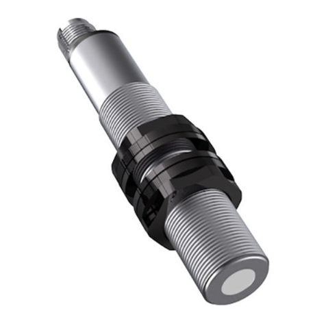
• The sensor can be mounted with the two M12 nuts (UFA2/UFA-CP) or M30 nuts (UFA-6000) which
are included in the delivery.
• The sensor has to be protected against mechanical loads for example shocks and impacts.
• The sensor can be mounted in any position, however a vibration-free or vibration-dampening
assembly must be observed.
• The transducer surface as well as the eld of the detection beam must be kept free mandatorily. You
need to pay attention on having no disturbing objects between the sensor and the target object
within the detection beam. Otherwise the sensor will detect the disturbing object instead of the
target object required.
• The object reects a part of the ultrasonic in the
diuse mode - this reected sound will be evaluated
by the sensor. Objects with a smooth surface are
reliably detected up to a tilting angle of approx. 10°.
The max. allowed tilting angle increases on objects
with a rough or heavy structured (granular) surface.

ELECTRICAL CONNECTION
Pin UFA2 and UFA-6000 UFA-150-CP Connection cable
K4P
Analog output Switching output Analog output Switching output
1 +V +V +V +V BN
2 Analog output Teach Teach Teach WH
3 GND GND GND GND BU
4 Teach Switching output Analog output Switching output BK
12
34
connector M12
(male)
+
S
T
–
Pin 1
Pin 2
Pin 3
Pin 4
circuit diagram UFA2/UFA-6000
analog output
Pin 1
Pin 2
Pin 3
Pin 4
+
S
T
–
+
T
–
+
teach
npn
pnp
circuit diagram UFA2/UFA-6000
switching output
TEACHING FUNCTION UFA2 AND UFA6000 ANALOG OUTPUT
Teaching the measurement range:
The measuring range is dened by two teach points. The output signal is scaled to the taught
measuring range.
Procedure:
1. Place the target on the position of the 1st teach point (i.e. where 0 V or 4 mA should be output).
2. Connect the teaching line (Pin 4) with +V (Pin 1) for 0.1...2 s. LED ashes slowly (1 Hz).
3. Within <20 s, place the target on the position for the 2nd teach point (i.e. where 10 V or 20 mA
should be output) and connect the teaching line with +V for 0.1...2 s.
4. LED ashes 2 times: teach procedure successful
LED ashes 4 times: teach procedure not successful
Changing the analog output signal:
The physical quantity (current/voltage) of the analog output is changed.
Procedure:
1. Connect the teaching line (Pin 4) with +V (Pin 1) for >6 s.
2. LED ashes 2 times: change successful
LED ashes 4 times: change not successful

TEACHING FUNCTION UFA2 AND UFA6000 SWITCHING OUTPUT
Teaching the window size:
The window size is dened by two switching limits.
Procedure:
1. Place the target on the position of near switching point.
2. Connect the teaching line (Pin 2) with +V (Pin 1) for 0.1...2 s. LED ashes slowly (1 Hz).
3. Within <20 s, place the target on the position of the far switching point and connect the teaching
line with +V for 0.1...2 s.
4. LED ashes 2 times: teach procedure successful
LED ashes 4 times: teach procedure not successful
2-step teaching:
Both conditions (background and object) can be taught successively. The switching point is placed
between the object and the background.
Procedure:
1. Place the target on the position of near switching point.
2. Connect the teaching line (Pin 2) with +V (Pin 1) for 2...4 s. LED ashes slowly (1 Hz).
3. Within <20 s, remove the target and connect the teaching line with +V for 2...4 s.
4. LED ashes 2 times: teach procedure successful
LED ashes 4 times: teach procedure not successful
Autoteach procedure:
Opens a teach window for 4...8 s and automatically teaches passing objects. The switching point is
placed between the object and the background.
Procedure:
1. Connect the teaching line (Pin 2) with +V (Pin 1) for 4...6 s. LED ashes fast (2 Hz).
2. Within the next 4...8 s, the autoteach procedure detects passing objects.
3. LED ashes 2 times: teach procedure successful
LED ashes 4 times: teach procedure not successful
Changing the switching function:
Changes between NO <=> NC. Causes a inversion of the switching output function (signal inversion on
objects within / outside the window).
Procedure:
1. Connect the teaching line (Pin 2) with +V (Pin 1) for >6 s.
2. LED ashes 2 times: change successful
LED ashes 4 times: change not successful

TEACHING FUNCTION UFA150CP ANALOG OUTPUT
Teaching the measurement range:
The two measuring limits are set by connecting the teaching line with either the power supply GND
(0V) or +V (+24 VDC). The voltage must be active for min. 1 s on the teaching line. During the teaching
procedure the LED shows if the sensor has detected the object. With GND the lower measuring limit
(0V or 4 mA) and with +V the upper measuring limit (10 V or 20 mA) is taught. Thus, it is possible to
teach a rising or a falling ramp.
Procedure:
1. Place the object on the lower measuring limit (i.e. where 0 V or 4 mA is desired).
2. Connect the teaching line with GND for >1 s.
3. Place the object on the upper measuring limit (i.e. where 10 V or 20 mA is desired).
4. Connect the teaching line with +V for >1 s.
Lower and upper measuring limits can also be programmed individually at a later time.
Attention: The teach wire must not be connected during normal operation. Those the sensor can be
operated after teaching with a 3 wire cable.
TEACHING FUNCTION UFA150CP SWITCHING OUTPUT
Setting of the switching points:
The switching points are set by connecting the teach wire with either the power supply GND (0 V)
or +V (+24 VDC). The voltage must be active for min. 1 s on the teaching line. During the teaching
procedure the LED shows if the sensor has detected the object.
Procedure:
Window operation closer NO:
1. Set target to near switching point
2. Teach switching point with GND
3. Set target to far switching point
4. Teach switching point with +V
Window operation opener NC:
1. Set target to near switching point
2. Teach switching target at with +V
3. Set target to far switching point
4. Teach switching point with GND
Switching point closer NO:
1. Set target to switching point
2. Teach switching point with +V
3. Point sensor at space (>1.5 m)
4. Teach with GND
Switching point opener NC:
1. Set target to switching point
2. Teach switching point with GND
3. Point sensor at space (>1.5 m)
4. Teach with +V
TEACHING FUNCTION UFA150CP SWITCHING OUTPUT
Retroective mode:
In window operation the sensor detects only targets which are within the window limits. The same
function can also be used to simulate a kind of retro-reective sensor. The reector is mounted in the
small window between Teach A and Teach B (see drawing below). In such setup the sensor detects also
targets which pass the sensor beam in a very at angle. The sensor would not detect such targets in
normal scan operation mode.
teach A teach B
target
reector
LED LIGHTING PATTERN UFA150CP
Red LED Yellow LED
During teaching procedure:
• object detected
• no object detected
• object not reliably detected
o
blinking
on
blinking
o
o
Normal operation PNP
Normal operation analog
o
on
switching status
on
Error on last status

DETECTION BEAMS
UFA2-200-A: Standard version with analog output
blind range
target: plate
100 x 100 mm
target: round bar
Ø 10 mm
0
5
10
15
-5
-10
-15
0 50 100 250150 200
UFA2-200-PN: Standard version with switching output
0 25 50 75 100 125 150 175 200 225
0
5
10
15
-5
-10
-15
blind range
target: plate
100 x 100 mm
target: round bar
Ø 10 mm
UFA2-FB-150: Focus beam version
0 20 40 60 10080 120 140 160
0
5
10
15
-5
-10
-15
20
-20
target: plate 20 x 20 mm
target: round bar
Ø 10 mm
UFA-150-CP: Chemical resistant version
0 20 40 60 10080 120 140 160
0
5
10
15
-5
-10
-15
20
-20
UFA-6000
blind range
target: plate 200 x 200 mm
target: round bar Ø 10 mm
600
400
200
0
-200
-400
-600
0 800 1600 2400 3200 4000 4800 5600 6400

INFLUENCES ON THE MEASUREMENT
Environmental inuences:
Ultrasonic sensors are made for the use in atmospheric air. Environmental Inuences like rain, snow,
dust or smoke have no inuence on the accuracy of the measurement. However, measurements under
pressure (higher that the atmospheric pressure) are not possible with ultrasound sensors.
Strong wind or air turbulences may lead to instability in measurement values. A ow speed up to a few
m/s is unproblematic and will have no inuence on the sensor’s accuracy.
Target Inuences:
• Liquids are excellently detectable with ultrasound. A classic application for ultrasonic sensors is level
measurement. The sound beam axis however must have a maximum deviation of 3° vertically to the
liquid level (no strong waves), otherwise the reected sound will miss the sensor.
• Hot Targets with high temperatures cause a thermal convection in the surrounding air. For this
reason the sound beam may be strongly diverted vertically to its axis, so that the echo is weakened,
or can no longer be received at all.
• For convex (cylindrical and spherical) surfaces every area element has a dierent angle to the sound
cone’s axis. The reected cone thus diverges and the portion of the sound energy reected to the
receiver is reduced correspondingly. The maximum range decreases with the decreasing size of the
cylinder (ball).
• The roughness and surface structures of the object to be detected also determine the scanning
capacities of the ultrasonic sensors. Surface structures that are larger than the ultrasound
wavelength, as well as coarse-grained bulk materials, reect ultrasound in a scattered manner, and
are not detected optimally by the sensor under these conditions.
• Hard material reects almost all of the impulse energy from ultrasound applications in a way that
makes them very easy to detect with ultrasound.
• Soft material, on the other hand, absorbs almost all of the impulse energy. It is thus harder to detect
with ultrasound. These materials include felt, cotton, coarse meshes, foam, etc.
• Thin-walled foils behave like soft materials. To be able to use ultrasound, the foil thickness should
be at least 0.01 mm.

DECLARATION OF CONFORMITY
Based on: EN 60947-5-2 + amendments (proximity switches)
EN 60947-5-7 + amendments (proximity sensors with analogue output)
This is to certify that the following products correspond to the mentioned specications.
Classication Ultrasonic Sensors
Series UFA-150-CP, UFA2, UFA-6000
Test on immunity IEC 61000-6-2 (Industry)
Type of test applied harmonized standards:
EN 61000-4-2, EN 61000-4-3, EN 61000-4-4
The declaration of conformity loses its validity if the product is misused or modied without proper
authorisation.
Taufkirchen, 30.06.2020 Andreas Täger
CEO
This manual suits for next models
3
Table of contents
Other Waycon Accessories manuals

Waycon
Waycon LX Series User manual

Waycon
Waycon UFP Series User manual

Waycon
Waycon LAM Series User manual

Waycon
Waycon UFA2 Series User manual

Waycon
Waycon SX300 Series User manual

Waycon
Waycon LAS Series User manual

Waycon
Waycon MAP Series User manual

Waycon
Waycon SX300 Series User manual

Waycon
Waycon MH60 Series User manual

Waycon
Waycon LZW2 Series User manual

Waycon
Waycon LVDT Series User manual

Waycon
Waycon SX50 Series User manual

Waycon
Waycon MSB Series User manual

Waycon
Waycon MAB-A User manual

Waycon
Waycon SX Series Operating and maintenance instructions

Waycon
Waycon UFP Series User manual

Waycon
Waycon EZ 105 Series User manual

Waycon
Waycon LLD-RS232 User manual