manuals.online logo
Brands
  1. Home
  2. •
  3. Brands
  4. •
  5. WE-EF
  6. •
  7. Lantern
  8. •
  9. WE-EF ASP500 LED User manual

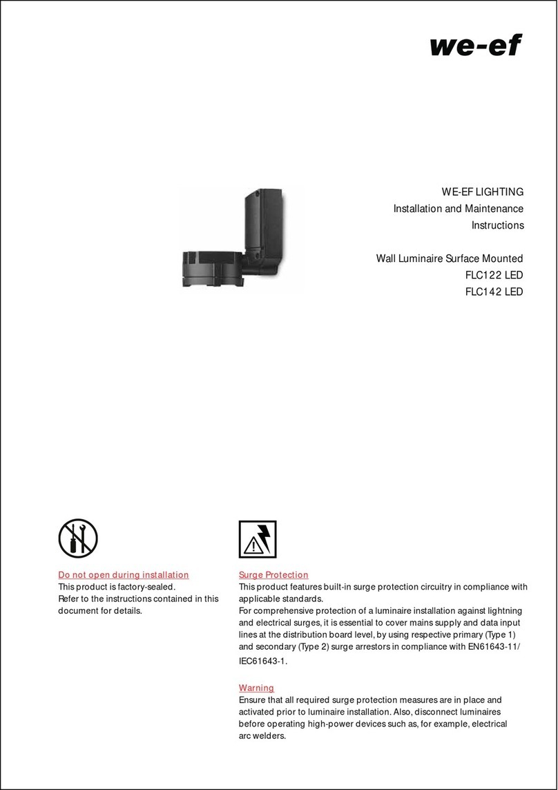
WE-EF ASP500 LED User manual

WE-EF LIGHTING Thailand
Tel +66 2 738 9610
info.asiapacific@we-ef.com
WE-EF LIGHTING USA
Tel +1 724 742 0030
info.usa@we-ef.com
WE-EF LEUCHTEN Germany
Tel +49 5194 909 0
info.germany@we-ef.com
WE-EF LUMIERE France
Tel +33 4 74 99 14 44
info.france@we-ef.com
WE-EF LIGHTING Australia
Tel +61 3 8587 0444
info.australia@we-ef.com
WE-EF HELVETICA Switzerland
Tel +41 22 752 49 94
info.switzerland@we-ef.com
www.we-ef.com
WE-EF LEUCHTEN
Montage- und
Wartungshinweise für
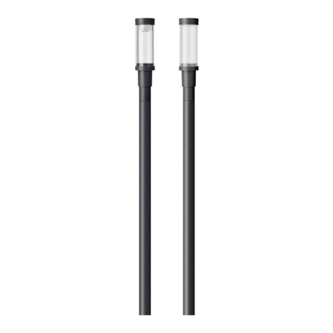
Mastleuchten
ASP500 LED
BSP500 LED
Installation and
Maintenance Instructions for
Post Top Luminaire
ASP500 LED
BSP500 LED
ASP500_BSP500_LED_010220 / 006-1177
Technische Änderungen vorbehalten.
Technical specifications are subject to change.
© WE-EF 2020
Sicherheit
Der Hersteller übernimmt keine Haftung für Schäden, die durch
unsachgemäßen Einsatz oder Montage entstehen.
Werden nachträglich Änderungen an Leuchten und/oder Zubehör
vorgenommen, so gilt derjenige als Hersteller, der diese Änderungen
vornimmt.
Safety indices
The manufacturer is then discharged from liability when damage is
caused by improper use or installation.
If any luminaire and/or accessory is subsequently modified, the
persons responsible for the modification shall be considered as
manufacturer.
Product Information / Surge Protection
This luminaire can be fitted with a surge protection device of type
2-3. The technical data can be found directly on the installed
device. If the surge protector has been triggered by an adverse
event , the luminaire is automatically disconnected from the mains.
In that case, the LED on the surge protector no longer lights up.
For comprehensive protection of the luminaire against lightning and
electrical surges, primary (Type 1) and secondary (Type 2) surge
arrestors must be installed into the power supply. We recommend a
combination arrestor (Type 1+2+3), which is installed in the control
cabinet.
The technical planner/installer is responsible for the proper selec-
tion, sizing and installation of the surge protection modules that
must be provided on site. Please note the various protection levels
for Class I and II, as well as the applicable statutory provisions
regarding surge protection. Installation and maintenance may only
be performed by a qualified electrician.
Produkthinweis / Überspannungsschutz
Diese Leuchte kann mit einem Überspannungsschutz Typ 2-3 aus-
gestattet sein. Die technischen Daten finden Sie in diesem Fall
direkt auf dem eingebauten Gerät. Wurde der Überspannungs-
schutz im Schadensfall ausgelöst, wird die Leuchte automatisch
vom Netz getrennt. Bei eingeschalteter Stromversorgung leuchtet
dann die Leuchtdiode am Überspannungsschutz nicht mehr.
Zu einem umfassenden Schutz der Leuchte gegen Blitzeinwirkungen
und Überspannungen ist es notwendig, zusätzlich einen Grob-
(Typ 1) und Mittelschutzableiter (Typ 2) in die Stromversorgung ein-
zubauen. Wir empfehlen einen Kombiableiter (Typ 1+2+3) für die
Montage im Schaltschrank.
Der Fachplaner/Installateur ist für die fachgerechte Auswahl,
Dimensionierung und die Montage der bauseits einzusetzenden
Überspannungsschutzbausteine verantwortlich. Bitte beachten Sie
die unterschiedlichen Schutzpegel für die Schutzklassen I und II
sowie die geltenden gesetzlichen Vorschriften zum Überspannungs-
schutz. Die Installation und Wartung ist nur von einem entsprechend
qualifiziertem Elektro-Fachbetrieb durchzuführen.
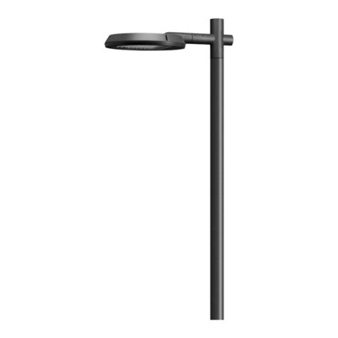
Ø max. 11 mm
Leuchtmittel / Light source
12 LED 24W / 24 LED 48W / 30 LED 60W / 36 LED 72W*
* Nominalleistung, aktualisierte Daten siehe www.we-ef.com
* Nominal power, for latest data refer to www.we-ef.com
Schutzklasse / Class I, II, ta = 25°C
Lichtpunkthöhe / Mounting height . . . . . . . . . . . . 3-4,5 m
Gewicht / Weight . . . . . . . . . . . . . . . . . . . . . . max. 13,5 kg
Windangriffsfläche / Windage area:
ASP534 . . . . . . . . . . . . . . . . . . . . . . . . . . . . . . . . 0,0898 m2
BSP534 . . . . . . . . . . . . . . . . . . . . . . . . . . . . . . . . 0,0930 m2
ASP544 . . . . . . . . . . . . . . . . . . . . . . . . . . . . . . . . 0,1343 m2
BSP544 . . . . . . . . . . . . . . . . . . . . . . . . . . . . . . . . 0,1246 m2
Mastleuchten
IP55, IK10
Post Top Luminaires
IP55, IK10 Benötigtes Werkzeug
– Schraubendreher Kreutzschlitz Gr. 1 / Gr. 2 Philips
– Schraubendreher 2,5 mm x 0,4 mm Klinge
– Drehmomentschrauber 5-20 Nm
– Innensechskantschlüssel 4 mm / 6 mm
Tools required
– Screwdriver recessed head size 1 / size 2 Philips
– Screwdriver with 2.5 mm x 0.4 mm blade
– Torque key 5-20 Nm
– 4 mm / 6 mm Allen keys
ø 560
M20
340
M20
430
ø 700
ASP534
ASP544
ø 560
M20
375
M20
430
ø 700
BSP534
BSP544
Installation
The product must be installed and maintained by a suitably
qualified professional in compliance with latest building/
construction and/or electrical regulations and relevant leg-
islation.
Notice: If the luminaire is modified by anybody other than
the original manufacturer, then the warranty will no longer
be valid and shall become the full responsibility
of the modifying person/organisation. Claims based on
defects attributable to improper installation and/or applica-
tion, and the consequences thereof, are excluded.
In case of component failure, LED replacement due to
abnormal circumstances or at end of life, replacement must
be carried out by a suitably qualified and trained profes-
sional.
In case of questions please contact our technical hotline:
+49 5194 909209 (from Monday - Friday from 08.00 until
16.00 hours.
Maintenance
Apart from cleaning the product’s exterior surfaces, no
special maintenance work is required. Do not use high-
pressure cleaners.
Montage
Montage und Wartung des Produkts dürfen nur von
Fachpersonal mit entsprechender beruflicher Qualifikation
in Übereinstimmung mit den geltenden bautechnischen
und/oder elektrischen Vorschriften durchgeführt werden.
Hinweis: Modifikationen an der Leuchte, die nicht durch
den Originalhersteller erfolgen, führen zum Erlöschen der
Garantie und Gewährleistung des Originalherstellers und
zum vollständigen Übergang der Verpflichtungen daraus
auf die modifizierende Person/Organisation. Ansprüche
aufgrund von Mängeln, die direkt oder indirekt auf unsach-
gemäße Montage und/oder Anwendung zurückzuführen
sind, sind ausgeschlossen.
Bei Ausfall von Komponenten, bei LED-Wechsel aufgrund
ungewöhnlicher Umstände oder am Ende der Lebensdauer
darf der Austausch nur von geschultem Fachpersonal mit
entsprechender beruflicher Qualifikation ausgeführt werden.
Bei Fragen wenden Sie sich bitte an unsere technische
Hotline unter +49 5194 909209 (Montag - Freitag von
08:00 Uhr bis 16:00 Uhr).
Wartung
Abgesehen von der äußerlichen Reinigung des Produkts ist
keine besondere Wartung erforderlich. Keine
Hochdruckreiniger verwenden.
Retrofitting HIT with LED
All the parts needed for retrofitting with LED are available
as a kit from WE-EF.
Important: It is possible to retrofit a gas discharge lumi-
naire with LED if the luminaire has a two-part luminaire
body (canopy and dome are fastened together).
The retrofit should only be carried out in the switched
off state.
Remove cover, gear-tray assembly and gas discharge lamp.
Connect the lead to the LED assembly. Insert the assembly
into the luminaire and screw tight. Mount the cover and
screw into place.
Umrüstung von HIT auf LED
Alle für die Umrüstung auf LED notwendigen Teile sind als
Kit von WE-EF erhältlich.
Achtung: Die Umrüstung einer Leuchte mit Gasentladung
auf LED ist möglich, wenn die Leuchte ein zweigeteiltes
Leuchtengehäuse hat (Schirm und Dom sind verschraubt).
Die Umrüstung darf nur in stromlosem Zustand durch-
geführt werden.
Abdeckung, Chassis und Gasentladungslampe entfernen.
Die Zuleitung an das LED Chassis anschließen.
Das Chassis in die Leuchte einsetzen und festschrauben.
Die Abdeckung aufsetzen und festschrauben.
L
K
H
Installation Procedure
1) Switch off the mains electrical supply.
Vorgehensweise
1) Spannungsfreiheit der Anschlussleitung herstellen.
2) Loosen fixing screw Aand remove cover Bdownwards.2) Die Befestigungsschraube Alösen und die Abdeckung
Bnach unten abnehmen.
B
A
3) Loosen the knurled thumb screw Kon the LED
housing. Rotate the LED housing until the mounting
screws Hcome into view. Loosen the three mounting
screws Hone after the other. Now you can remove the
complete gear-tray.
3) Rändelschraube Klösen und die drei Befestigungs-
schrauben Hdurch Drehen der Platinenaufnahme
suchen und lösen. Jetzt kann das komplette Chassis
aus der Leuchte genommen werden.
F
E
J
N
L
G
H
4) Fasten the luminaire with the M20 adaptor Eto the
bracket and depending on bracket used secure 1 or
4 threaded pins Fwith 10 Nm each.
5) Take off the plug connector Jand connect it to the
connecting cable. Connect the neutral conductor (N)
and phase (L1), for safety class I additionally the
protective conductor to the corresponding marked
contacts J, in case class II is required insert the
double isolated connecting cable. Check that rating
shown on the luminaire label conforms with the mains
electrical supply. Now plug the connector Jon to the
socket, lead the cable through the strain relief Gand
firmly tighten the screws of the strain relief G.
6) Insert the gear-tray into the luminaire and firmly tight-
en the 3 fixing screws H. Align the LED in relation to
the road. The arrow always points towards the road.
Firmly tighten the knurled thumb screw K.
7) Evenly place on the cover Band tighten hand-tight
the fixing screws A.
8) Re-check the correct fixing of the luminaire to the
bracket. Not correctly fastened luminaires can fall
down.
4) Die Leuchte mit dem M20 Adapter Eam Ausleger be-
festigen und über den/die Gewindestift/e F je nach
Ausleger 1 oder 4 Schrauben M8 mit je 10 Nm sichern.
5) Die Steckverbindung Jabziehen und an die Anschluss-
leitung anschließen. Nulleiter (N) und Phase (L1), bei
Schutzklasse I zusätzlich den Schutzleiter an die
entsprechend markierten Kontakte Janschließen, bei
Schutzklasse II die Anschlussleitung doppelt isoliert
einführen. Vergleichen Sie die örtliche Spannung und

Frequenz mit den Daten auf dem Leistungsschild. Jetzt
den Stecker Jauf die Buchse aufstecken, das Kabel
durch die Zugentlastung Gführen und die Schrauben
an der Zugentlastung Gfest anziehen.
6) Das Chassis in die Leuchte einsetzen und die drei
Befestigungsschrauben Hfest anziehen. Die Platinen-

aufnahme zur gewünschten Verkehrsfläche ausrichten
(Pfeil zeigt i.d.R. zur Verkehrsfläche) und die

Befestigungsmutter Kvon Hand fest anziehen.
7) Die Abdeckung Bgleichmäßig aufsetzen und die
Befestigungsschraube Ahandfest anziehen.
8) Prüfen Sie nochmals den festen Sitz der Leuchte am
Ausleger. Nicht korrekt befestigte Leuchten können
herabfallen.

This manual suits for next models

1

Other WE-EF Lantern manuals

WE-EF PFL540 LED User manual

WE-EF

WE-EF PFL540 LED User manual

WE-EF RFL530-SE LED User manual

WE-EF

WE-EF RFL530-SE LED User manual

WE-EF RMC320 LED User manual

WE-EF

WE-EF RMC320 LED User manual

WE-EF RFL540-SE LED Series User manual

WE-EF

WE-EF RFL540-SE LED Series User manual

WE-EF ETC310-FS LED User manual

WE-EF

WE-EF ETC310-FS LED User manual

WE-EF RLS400 LED Series User manual

WE-EF

WE-EF RLS400 LED Series User manual

WE-EF VFL530 User manual

WE-EF

WE-EF VFL530 User manual

WE-EF ETV100 Series User manual

WE-EF

WE-EF ETV100 Series User manual

WE-EF VFL530-SE LED User manual

WE-EF

WE-EF VFL530-SE LED User manual

WE-EF FLC122 LED User manual

WE-EF

WE-EF FLC122 LED User manual

WE-EF PFL230 LED User manual

WE-EF

WE-EF PFL230 LED User manual

WE-EF CFT500 LED Series User manual

WE-EF

WE-EF CFT500 LED Series User manual

WE-EF ETC330-GB LED User manual

WE-EF

WE-EF ETC330-GB LED User manual

WE-EF ETC100-GB LED Series Technical specifications

WE-EF

WE-EF ETC100-GB LED Series Technical specifications

WE-EF PFL230 User manual

WE-EF

WE-EF PFL230 User manual

WE-EF VFL500 LED Series User manual

WE-EF

WE-EF VFL500 LED Series User manual

WE-EF QLS400 Series User manual

WE-EF

WE-EF QLS400 Series User manual

WE-EF ETC320-FS LED User manual

WE-EF

WE-EF ETC320-FS LED User manual

WE-EF RMT320 LED User manual

WE-EF

WE-EF RMT320 LED User manual

WE-EF ALP530 User manual

WE-EF

WE-EF ALP530 User manual

WE-EF FLC122 LED User manual

WE-EF

WE-EF FLC122 LED User manual

WE-EF ETC330-FS User manual

WE-EF

WE-EF ETC330-FS User manual

WE-EF AL530 User manual

WE-EF

WE-EF AL530 User manual

WE-EF PFL240 LED User manual

WE-EF

WE-EF PFL240 LED User manual

Popular Lantern manuals by other brands

LUG URBINO TWILIGHT LED Installation instruction

LUG

LUG URBINO TWILIGHT LED Installation instruction

SLV Elektronik DEWI DESK operating manual

SLV Elektronik

SLV Elektronik DEWI DESK operating manual

Prilux Energy Tech HE instruction manual

Prilux

Prilux Energy Tech HE instruction manual

ALS PINLED PINR quick start guide

ALS

ALS PINLED PINR quick start guide

Hess REVARA L600 manual

Hess

Hess REVARA L600 manual

LED2WORK INROLED 50 Power Ecolab AC User instructions

LED2WORK

LED2WORK INROLED 50 Power Ecolab AC User instructions

Evluma ROADMAX Series installation instructions

Evluma

Evluma ROADMAX Series installation instructions

LIGMAN NEON Series Installation and service manual

LIGMAN

LIGMAN NEON Series Installation and service manual

Brilum OPTIMA 60 Installation and operating manual

Brilum

Brilum OPTIMA 60 Installation and operating manual

Lighting Technologies ARCTIC.OPL ECO LED 1200 4000K manual

Lighting Technologies

Lighting Technologies ARCTIC.OPL ECO LED 1200 4000K manual

Eaton Champ VMVL Series Installation & maintenance information

Eaton

Eaton Champ VMVL Series Installation & maintenance information

Cooper Crouse-Hinds ILLUMINATOR EVFT Series Installation & maintenance information

Cooper Crouse-Hinds

Cooper Crouse-Hinds ILLUMINATOR EVFT Series Installation & maintenance information

ezilight Lamp XL user manual

ezilight

ezilight Lamp XL user manual

Westfalia Wetelux 86 73 98 Original instructions

Westfalia

Westfalia Wetelux 86 73 98 Original instructions

SLV 111260 operating manual

SLV

SLV 111260 operating manual

Angelcare Pabobo Shakies instruction manual

Angelcare

Angelcare Pabobo Shakies instruction manual

Optimum WBL3 Instructions for use

Optimum

Optimum WBL3 Instructions for use

Solight WO216 instruction manual

Solight

Solight WO216 instruction manual

manuals.online logo
manuals.online logoBrands
  • About & Mission
  • Contact us
  • Privacy Policy
  • Terms and Conditions

Copyright 2025 Manuals.Online. All Rights Reserved.