manuals.online logo
Brands
  1. Home
  2. •
  3. Brands
  4. •
  5. WE-EF
  6. •
  7. Lantern
  8. •
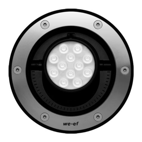
  9. WE-EF RFL540-SE LED Series User manual

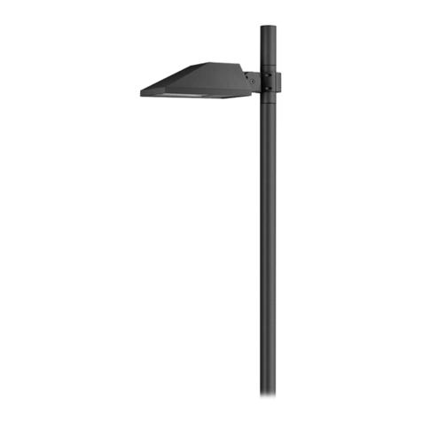
WE-EF RFL540-SE LED Series User manual

Sicherheit
Der Hersteller übernimmt keine Haftung für Schäden, die durch
unsachgemäßen Einsatz oder Montage entstehen.
Werden nachträglich Änderungen an Leuchten und/oder Zubehör
vorgenommen, so gilt derjenige als Hersteller, der diese Änderungen
vornimmt.
Safety indices
The manufacturer is then discharged from liability when damage is
caused by improper use or installation.
If any luminaire and/or accessory is subsequently modified, the
persons responsible for the modification shall be considered as
manufacturer.
Product Information / Surge Protection
This luminaire can be fitted with a surge protection device of type
2-3. The technical data can be found directly on the installed
device. If the surge protector has been triggered by an adverse
event , the luminaire is automatically disconnected from the mains.
In that case, the LED on the surge protector no longer lights up.
For comprehensive protection of the luminaire against lightning and
electrical surges, primary (Type 1) and secondary (Type 2) surge
arrestors must be installed into the power supply. We recommend a
combination arrestor (Type 1+2+3), which is installed in the control
cabinet.
The technical planner/installer is responsible for the proper selec-
tion, sizing and installation of the surge protection modules that
must be provided on site. Please note the various protection levels
for Class I and II, as well as the applicable statutory provisions
regarding surge protection. Installation and maintenance may only
be performed by a qualified electrician.
Produkthinweis / Überspannungsschutz
Diese Leuchte kann mit einem Überspannungsschutz Typ 2-3 aus-
gestattet sein. Die technischen Daten finden Sie in diesem Fall
direkt auf dem eingebauten Gerät. Wurde der Überspannungs-
schutz im Schadensfall ausgelöst, wird die Leuchte automatisch
vom Netz getrennt. Bei eingeschalteter Stromversorgung leuchtet
dann die Leuchtdiode am Überspannungsschutz nicht mehr.
Zu einem umfassenden Schutz der Leuchte gegen Blitzeinwirkungen
und Überspannungen ist es notwendig, zusätzlich einen Grob-
(Typ 1) und Mittelschutzableiter (Typ 2) in die Stromversorgung ein-
zubauen. Wir empfehlen einen Kombiableiter (Typ 1+2+3) für die
Montage im Schaltschrank.
Der Fachplaner/Installateur ist für die fachgerechte Auswahl,
Dimensionierung und die Montage der bauseits einzusetzenden
Überspannungsschutzbausteine verantwortlich. Bitte beachten Sie
die unterschiedlichen Schutzpegel für die Schutzklassen I und II
sowie die geltenden gesetzlichen Vorschriften zum Überspannungs-
schutz. Die Installation und Wartung ist nur von einem entsprechend
qualifiziertem Elektro-Fachbetrieb durchzuführen.
WE-EF LIGHTING Thailand
Tel +66 2 738 9610
info.asiapacific@we-ef.com
WE-EF LIGHTING USA
Tel +1 724 742 0030
info.usa@we-ef.com
WE-EF LEUCHTEN Germany
Tel +49 5194 909 0
info.germany@we-ef.com
WE-EF LUMIERE France
Tel +33 4 74 99 14 44
info.france@we-ef.com
WE-EF LIGHTING Australia
Tel +61 3 8587 0444
info.australia@we-ef.com
WE-EF HELVETICA Switzerland
Tel +41 22 752 49 94
info.switzerland@we-ef.com
www.we-ef.com
RFL500_SE_LED_010320 / 006-0887
Technische Änderungen vorbehalten.
Technical specifications are subject to change.
© WE-EF 2020
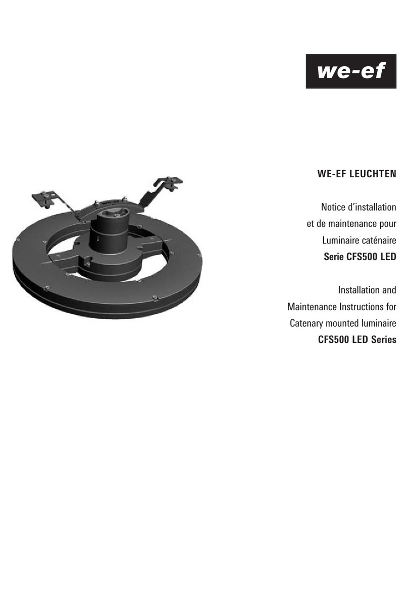
WE-EF LEUCHTEN
Montage- und
Wartungshinweise für
Mastleuchte
Serie RFL500-SE LED
Installation and
Maintenance Instructions for
Post Mounted Luminaire
RFL540-SE LED Series
ø 460
ø 42 x 100
ø 460
81
19
ø 570
ø 60 x 100
ø 570
82
38
RFL530-SE LED RFL540-SE LED
Ø 9 – 14 mm 1,5 mm2
Post Mounted Luminaires
IP66, IK07
Mastaufsatzleuchten
IP66, IK07
Benötigtes Werkzeug
– Innensechskantschlüssel 4 mm
– Seitenschneider
Tools required
– 4 mm Allen key
– diagonal cutting pliers
Leuchtmittel / Light source
RFL530-SE LED: . . . . . . . . . . .12 LED 12W / 24 LED 24W*
. . . . . . . . . . . . . . . . . . . . . . . . .12 LED 24W / 24 LED 48W*
RFL540-SE LED: . . . . . . . . . . .36 LED 36W / 48 LED 48W*
. . . . . . . . . . . . . . . . . . . . . . . . .36 LED 72W / 48 LED96W*
* Nominalleistung, aktualisierte Daten siehe www.we-ef.com
* Nominal powerfor latest data refer to www.we-ef.com
Schutzklasse / Class I, II, ta = 25°C
Lichtpunkthöhe / Mounting height: . . . . . . . . . . . . . . 3-8 m
Montageart: horizontal, nach unten strahlend
Installation: horizontal, light output downwards
Gewicht / Weight: RFL530-SE LED . . . . . max. 9,3 kg
RFL540-SE LED . . . . . max. 15,0 kg
Windangriffsfläche / Windage area:
RFL530-SE LED . . . . . max. 0,166 m2
RFL540-SE LED . . . . . max. 0,255 m2
Installation
The product must be installed and maintained by a suitably
qualified professional in compliance with latest building/
construction and/or electrical regulations and relevant leg-
islation.
Notice: If the luminaire is modified by anybody other than
the original manufacturer, then the warranty will no longer
be valid and shall become the full responsibility
of the modifying person/organisation. Claims based on
defects attributable to improper installation and/or applica-
tion, and the consequences thereof, are excluded.
In case of component failure, LED replacement due to
abnormal circumstances or at end of life, replacement must
be carried out by a suitably qualified and trained profes-
sional.
In case of questions please contact our technical hotline:
+49 5194 909209 (from Monday - Friday from 08.00 until
16.00 hours.
Maintenance
Apart from cleaning the product’s exterior surfaces, no
special maintenance work is required. Do not use high-
pressure cleaners.
Protect our environment: Discard used LEDs in compliance
with the most recent environmental legislation.
Montage
Montage und Wartung des Produkts dürfen nur von
Fachpersonal mit entsprechender beruflicher Qualifikation
in Übereinstimmung mit den geltenden bautechnischen
und/oder elektrischen Vorschriften durchgeführt werden.
Hinweis: Modifikationen an der Leuchte, die nicht durch
den Originalhersteller erfolgen, führen zum Erlöschen der
Garantie und Gewährleistung des Originalherstellers und
zum vollständigen Übergang der Verpflichtungen daraus
auf die modifizierende Person/Organisation. Ansprüche
aufgrund von Mängeln, die direkt oder indirekt auf unsach-
gemäße Montage und/oder Anwendung zurückzuführen
sind, sind ausgeschlossen.
Bei Ausfall von Komponenten, bei LED-Wechsel aufgrund
ungewöhnlicher Umstände oder am Ende der Lebensdauer
darf der Austausch nur von geschultem Fachpersonal mit
entsprechender beruflicher Qualifikation ausgeführt werden.
Bei Fragen wenden Sie sich bitte an unsere technische
Hotline unter +49 5194 909209 (Montag - Freitag von
08:00 Uhr bis 16:00 Uhr).
Wartung
Abgesehen von der äußerlichen Reinigung des Produkts ist
keine besondere Wartung erforderlich. Keine
Hochdruckreiniger verwenden.
Für die Entsorgung der LEDs sind die zur Zeit gültigen
Umweltgesetze zu beachten.
4) Should the cable connector not fit through the out-
reach bracket C(pic. 9), then this must first be disas-
sembled from the connecting lead, then the connecting
lead Ecan be passed through the outreach bracket C.
Attach luminaire to outreach bracket Cand tighten the
fixing screws Bwith an approximate torque of 5 Nm.
Re-assemble the cable connector to the outreach
bracket (pole side).
5) All brackets, that do not allow the cable connector to
be passed through e.g., RX0, RI_ or other adapters, the
luminaire must be connected in accordance with the
wiring diagram (fig. 10-11).
4) Sollte der Leitungsverbinder nicht durch den Ausleger
Cpassen (Abb. 9), muss dieser zuerst von der
Anschlussleitung demontieret werden, anschließend
die Anschlussleitung Edurch den Ausleger Cziehen.
Die Leuchte am Ausleger Cansetzen und die
Befestigungsschrauben Bmit einem Anziehmoment
von 5 Nm anziehen. Den Leitungsverbinder hinter dem
Ausleger wieder montieren.

5) Sollte ein Durchführen der Leitungsverbinder nicht
möglich sein wie z.B. bei RX0, RI_ oder anderen
Stutzen, muss die Leuchte gemäß Anschlussplan ange-
schlossen werden (Abb. 10-11).
E
H
Abb. 11
pic. 11
ON-OFF
ADVANCED
1-10 V
DALI
BASIC
G
Abb. 10
pic. 10
Anschlussplan Leuchte
Wiring diagram luminaire
A
A
E
C
B
Abb. 9
fig. 9
Abb. 8
fig. 8
Installation Procedure
Luminaire prewired, do not open!
1) Switch off the mains electrical supply.
2) Cut cable to the corresponding height of the pole and
connect cable to the connector A(fig. 1-6).
WE-EF Eco Step Dim® Advanced and
not dimmable luminaires
Class I Phase (L1) to 1, Neutral (N) to 3 and
Earthing
Class II Phase (L1) to 1, Neutral (N )to 3
WE-EF Eco Step Dim® Basic
Class I Phase (L1) to 1, Control Phase (L2) to 2,
Neutral (N) to 3 and Earthing
Class II Phase (L1) to 1, Control Phase (L2) to 2,
Neutral (N) to 3
1-10V / DALI
Class I Phase (L1) to 1, Neutral (N) to N, Control
Phase (+) to 2, Control Phase (–) to 3 and
Earthing
Class II Phase (L1) to 1, Neutral (N) to 3,
Control Phase (+) to 2, Control Phase (–) to 4
Compare the local voltage and frequency with date
mentioned on the label of the luminaire.
Screw the gland nut together, tightening to a torque
of 5 Nm (fig. 5).
Pull the connecting cable through the pole.
3) Place the luminaire on the pole and tighten the fixing
screws B, tightening to a torque of 10 Nm.
Vorgehensweise
Leuchte ist vorverdrahtet, zum Anschließen nicht öffnen!
1) Spannungsfreiheit der Anschlussleitung
herstellen.
2) Entsprechend der Masthöhe zugeschnittene Anschluss-
leitung an den Leitungsverbinder Aanschließen
(Abb. 1-6).
WE-EF Eco Step Dim® Advanced und
nicht dimmbare Leuchten
SKI Phase (L1) an 1, Neutralleiter (N) an 3 und
Schutzleiter an
SKII Phase (L1) an 1, Neutralleiter (N )an 3
WE-EF Eco Step Dim® Basic
SKI Phase (L1) an 1, Steuerphase (L2) an 2,
Neutralleiter (N) an 3 und Schutzleiter an
SKII Phase (L1) an 1, Steuerphase (L2) an 2,
Neutralleiter (N) an 3
1-10V / DALI
SKI Phase (L1) an 1, Neutralleiter (N) an N,
Steuerphase (+) an 2, Steuerphase (–) an 3
und Schutzleiter an
SKII Phase (L1) an 1, Neutralleiter (N) an 3,
Steuerphase (+) an 2, Steuerphase (–) an 4
Vergleichen Sie die örtliche Spannung und Frequenz
mit den Daten auf dem Leistungsschild.
Verschrauben Sie die Überwurfmutter mit einem
Anzugsdrehmoment von 5 Nm (Abb. 5).
Das Anschlusskabel durch den Mast ziehen.
3) Die Leuchte an den Mast ansetzen und die Befestigungs-
schrauben Bder Leuchte mit einem Anziehmoment von
10 Nm anziehen.
Abb. 1
fig. 1
Abb. 3
fig. 3
Abb. 2
fig. 2
Abb. 4
fig. 4
Abb. 5
fig. 5
Abb. 6
fig. 6
Abb. 7
fig. 7

This manual suits for next models

1

Other WE-EF Lantern manuals

WE-EF DLO200 Series User manual

WE-EF

WE-EF DLO200 Series User manual

WE-EF FLC122 LED User manual

WE-EF

WE-EF FLC122 LED User manual

WE-EF CTY150 LED User manual

WE-EF

WE-EF CTY150 LED User manual

WE-EF VFL500 LED Series User manual

WE-EF

WE-EF VFL500 LED Series User manual

WE-EF ETC320-GBLED User manual

WE-EF

WE-EF ETC320-GBLED User manual

WE-EF XLO200 LED Series User manual

WE-EF

WE-EF XLO200 LED Series User manual

WE-EF ETC130-FS LED User manual

WE-EF

WE-EF ETC130-FS LED User manual

WE-EF CFT500 LED Series User manual

WE-EF

WE-EF CFT500 LED Series User manual

WE-EF ETC120-FS LED User manual

WE-EF

WE-EF ETC120-FS LED User manual

WE-EF ASP500 LED User manual

WE-EF

WE-EF ASP500 LED User manual

WE-EF VFL530 User manual

WE-EF

WE-EF VFL530 User manual

WE-EF AL530 User manual

WE-EF

WE-EF AL530 User manual

WE-EF RBL640 User manual

WE-EF

WE-EF RBL640 User manual

WE-EF RFL500-SE Series User manual

WE-EF

WE-EF RFL500-SE Series User manual

WE-EF RLS410 LED User manual

WE-EF

WE-EF RLS410 LED User manual

WE-EF ETC100-GB LED Series User manual

WE-EF

WE-EF ETC100-GB LED Series User manual

WE-EF ETC310-FS LED User manual

WE-EF

WE-EF ETC310-FS LED User manual

WE-EF QLS410 LED User manual

WE-EF

WE-EF QLS410 LED User manual

WE-EF RMC320 LED User manual

WE-EF

WE-EF RMC320 LED User manual

WE-EF ASP500 LED User manual

WE-EF

WE-EF ASP500 LED User manual

WE-EF ETC339-FS LED User manual

WE-EF

WE-EF ETC339-FS LED User manual

WE-EF RFL530 User manual

WE-EF

WE-EF RFL530 User manual

WE-EF ETC310-FS User manual

WE-EF

WE-EF ETC310-FS User manual

WE-EF ETC120-GB LED User manual

WE-EF

WE-EF ETC120-GB LED User manual

Popular Lantern manuals by other brands

olympia electronics GR-2110 quick start guide

olympia electronics

olympia electronics GR-2110 quick start guide

IMG JUGGER PIX user manual

IMG

IMG JUGGER PIX user manual

Home Decorators Collection 2642M-PHO Use and care guide

Home Decorators Collection

Home Decorators Collection 2642M-PHO Use and care guide

less'n'more Athene A-SL General Instructions for Use

less'n'more

less'n'more Athene A-SL General Instructions for Use

Emos SSD-6605 instructions

Emos

Emos SSD-6605 instructions

ORIUM Elona instruction manual

ORIUM

ORIUM Elona instruction manual

Gama Sonic 14B50063 instruction manual

Gama Sonic

Gama Sonic 14B50063 instruction manual

kenall HIGH BAY MAX HBM Series installation instructions

kenall

kenall HIGH BAY MAX HBM Series installation instructions

FEUERHAND hurricane lantern user guide

FEUERHAND

FEUERHAND hurricane lantern user guide

MUNDUS Rota instruction manual

MUNDUS

MUNDUS Rota instruction manual

SO-TECH Triangolo 53286571 quick start guide

SO-TECH

SO-TECH Triangolo 53286571 quick start guide

Larson Electronics LE-2206 instruction manual

Larson Electronics

Larson Electronics LE-2206 instruction manual

Saxby Lighting Reeve 2 instruction manual

Saxby Lighting

Saxby Lighting Reeve 2 instruction manual

Vimar Eikon 20384 Series manual

Vimar

Vimar Eikon 20384 Series manual

mitzi HL269201 DEMI Assembly and mounting instructions

mitzi

mitzi HL269201 DEMI Assembly and mounting instructions

Philips GSA ST321Y manual

Philips

Philips GSA ST321Y manual

Anslut 018972 operating instructions

Anslut

Anslut 018972 operating instructions

luminii Tavan TAV Series installation instructions

luminii

luminii Tavan TAV Series installation instructions

manuals.online logo
manuals.online logoBrands
  • About & Mission
  • Contact us
  • Privacy Policy
  • Terms and Conditions

Copyright 2025 Manuals.Online. All Rights Reserved.