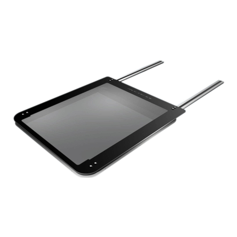
Webasto 40 Series User manual

Marine Roof
Techo solar marino
Marinedach
Toit ouvrant Marine
Marine schuifdak
Tetti per la Nautica
Installation Instructions
Instrucciones de montaje
Einbauanweisung
Notice de montage
Montagehandleiding
Istruzioni di montaggio
4 Series

40 Series
TABLE OF CONTENTS / INDICE / INHALTSVERZEICHIS / INDEX / INHOUDSOPGAVE / INDICE
English .................................................................................................................................... 3
1. INTRODUCTION ................................................................................................. 5
2. TECHNICAL SPECIFICATION................................................................................ 6
3. DESCRIPTION OF THE WEBASTO 4 SERIES ........................................................ 8
4. INSTALLATION .................................................................................................. 9
5. ELECTRICAL CONNECTIONS ............................................................................ 18
6. RESETTING ...................................................................................................... 19
7. ELECTRICAL DIAGRAM ................................................................................... 2
8. SAFETY ............................................................................................................ 21
9. SUPPORT ......................................................................................................... 22
1 . CHECKLIST ....................................................................................................... 23
Español ................................................................................................................................. 25
1. INTRODUCCIÓN ............................................................................................... 27
2. ESPECIFICACIONES TÉCNICAS .......................................................................... 28
3. DESCRIPCIÓN DEL WEBASTO SERIE 4 ............................................................. 3
4. INSTALACIÓN .................................................................................................. 31
5. CONEXIONES ELÉCTRICAS ............................................................................... 4
6. RESTABLECIMIENTO ........................................................................................ 41
7. DIAGRAMA ELÉCTRICO .................................................................................. 42
8. SEGURIDAD ..................................................................................................... 43
9. ASISTENCIA ..................................................................................................... 44
1 . LISTA DE VERIFICACIÓN ................................................................................... 45
Deutsch................................................................................................................................. 47
1. EINLEITUNG ..................................................................................................... 49
2. TECHNISCHE SPEZIFIKATION ............................................................................ 5
3. BESCHREIBUNG DER WEBASTO 4 SERIES........................................................ 52
4. INSTALLATION ................................................................................................ 53
5. ELEKTRISCHE ANSCHLÜSSE ............................................................................. 62
6. ZURÜCKSETZEN ............................................................................................... 63
7. ELEKTRISCHER SCHALTPLAN .......................................................................... 64
8. SICHERHEIT ..................................................................................................... 65
9. SUPPORT ......................................................................................................... 66
1 . CHECKLISTE ..................................................................................................... 67
Français................................................................................................................................. 69
1. INTRODUCTION ............................................................................................... 71
2. SPÉCIFICATION TECHNIQUE ............................................................................. 72
3. DESCRIPTION DE LA 4 SERIES WEBASTO ........................................................ 74
4. MONTAGE ...................................................................................................... 75
5. PARTIE ÉLECTRIQUE ........................................................................................ 84
6. RÉINITIALISATION ........................................................................................... 85
7. SCHÉMA ÉLECTRIQUE .................................................................................... 86
8. SÉCURITÉ ........................................................................................................ 87
9. ASSISTANCE TECHNIQUE ................................................................................ 88
1 . LISTE DE CONTRÔLE......................................................................................... 89
40 Series
Nederlands ............................................................................................................................91
1. INLEIDING.........................................................................................................93
2. TECHNISCHE SPECIFICATIE................................................................................94
3. BESCHRIJVING VAN DE WEBASTO 4 SERIES ....................................................96
4. MONTAGE .......................................................................................................97
5. ELEKTRISCHE AANSLUITINGEN ......................................................................1 6
6. RESETTEN ......................................................................................................1 7
7. ELEKTRISCH SCHEMA ....................................................................................1 8
8. VEILIGHEID ....................................................................................................1 9
9. HOTLINE ........................................................................................................11
1 . CONTROLE-LIJST .............................................................................................111
Italiano ................................................................................................................................113
1. INTRODUZIONE...............................................................................................115
2. SPECIFICHE TECNICHE.....................................................................................116
3. DESCRIZIONE DEL WEBASTO 4 SERIES ..........................................................118
4. INSTALLAZIONE .............................................................................................119
5. COLLEGAMENTI ELETTRICI .............................................................................128
6. RESETTAGGIO ................................................................................................129
7. SCHEMA ELETTRICO .....................................................................................13
8. SICUREZZA .....................................................................................................131
9. ASSISTENZA ...................................................................................................132
1 . LISTA DI CONTROLLO .....................................................................................133

40 Series
3
NOTE
For installation and repair of Webasto roofs you will need a special training by Webasto, technical
documentation, special tools and special equipment.
Do NOT install or repair Webasto roofs, if you have not successfully finished the training by Webasto for
acquiring the necessary technical skills. Do NOT install or repair Webasto roofs, if you do not have the
necessary technical documentation, tools or equipment.
ALWAYS follow the Webasto installation and service instructions and mind all warning indications.
Webasto does not assume any liabilities for defects or damages caused by for installation untrained
personnel.
SYMBOLS
On each page you can find a symbol of the kind of tasks explained on that page.
Mechanical tasks
Electrical connections
Special parts of the text are marked with these symbols:
Indication of danger of injuries or accidents
Indication of danger of damaging the product
Indication of another source of information
Indication of technically special features

40 Series
4
SCOPE OF DELIVERY
• Top frame (incl. mechanisms)
• Glass panel assembly (incl. tool bit for fixing screws)
• Rails, left and right
• Bag with hardware, rail covers (2 pcs), rail end caps (2 pcs)
• Grease Isoflex® Topas L32
• Motor cover incl. fixing screws (optional)
• Brackets for motor cover incl. fixing screws (2 pcs, optional)
• Installation instructions
• Operating instructions
OTHER MATERIALS REQUIRED
• Hardware to fix top frame and rails: screws M4 stainless steel, pan, dome or round head
•High quality, acid-free, UV resistant, silicon mastic sealant
• Loctite 243
NECESSARY TOOLS
• Drilling machine
• Drills ø 3.2 mm, ø 4.5 mm, ø 5 mm
• Countersink drill bit
• Taps M4, M6
• Torx® keys
• Mastic gun
• Screwdrivers
Personnel
Perform roof installation with at least 2 persons. This makes the operation easier and reduces the risk of damage.
Protection
Improper use of tools can lead to injuries or damage to the ship or roof!
Thoroughly read tool instructions prior to using.
Before using any specialized tools, ensure to know all rules and regulations in your country.
Cover interior and exterior of the ship or vehicle with protection materials (covers, cloths, etc.) to reduce the risk of damage.
Also wear protective clothing like ear protection, safety shoes, safety goggles and protective gloves.

40 Series
5
1. INTRODUCTION
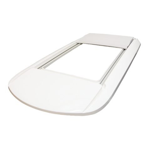
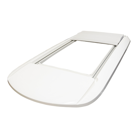
The Webasto 4 Series is an electrically operated sliding roof for ventilation purposes. The marine roof has been designed for
a large range of applications and can be installed easily in various ships.
It is suitable for fitting in area III and usage for ship type with design-category B.
All parts are made from high corrosion resistant materials.
Webasto 4 Series marine roofs are very easy to install and even retrofit is possible.
Product Benefits:
• Opens and closes quietly
• Suitable for ventilation of the cabin
• Glass panel made of 8 mm tempered safety glass
• Electrical operation
• Large opening
• Water-proof and robust
• Simple installation
• World-wide service network

40 Series
6
2. TECHNICAL SPECIFICATION
L1
R5
W1
R1
W2
L4
L3
H
Z
XY
Cut out
L5
Marine roof
R7
R1
R3 R2
L2
R4
R6

40 Series
7
Description Webasto 4 Series
General
Part no. 3394952_
Operation Continuous electric
Operation voltage (DC) [V] 12
Power (at 2 A, 12 V) [W] 24
Control panel Rocker switch
Installation method Frame and rails screwed on deck / roof / surface
Average installation time [h] 4
Frame materials AlMg Si .5
Surface treatment Anodized
Glass panel Glass, tempered, grey, 8 mm
Allowable weight Not designed as walking surface
Max. load 7 kg, including weight glass panel
assembly
(in accordance with ISO 12216)
Allowable temperature [°C] -1 to +75
Possibility to use as escape hatch No
Cut out dimensions
L1 Total length [mm] 915 +4 / -
L2 Length straight part [mm] 89
W1 Width [mm] 1,32 +4 / -
R1 Corner radius, front/rear [mm] 8 ± 2
R2 Cross curvature [mm] 7,62
R3 Front radius [mm] 2, 32
Longitudinal curvature [mm] Uncurved
Dimensions marine roof
L3 Overall length [mm] 1,675 (1,875 in combination with fixed panel)
L4 Length glass panel [mm] 1, 4
L5 Rail length [mm] 71 (91 in combination with fixed panel)
W2 Width [mm] 1,378
H Height [mm] 49
R4 Corner radius glass panel, rear [mm] 25
R5 Corner radius glass panel, front [mm] 1
R6 Front radius glass panel [mm] 2, 55
R7 Cross curvature [mm] 7,669
Longitudinal curvature [mm] Uncurved
Glass panel displacement
“tilt” (Z-direction) [mm] 22
“slide” (X-direction) [mm] approx. 55
Weight
[kg] approx. 4 - 5
Optics
Colour glass panel Grey tinted
Interior Blank anodized
Glass panel fixation Bolted on mechanism

40 Series
8
3. DESCRIPTION OF THE WEBASTO 4 SERIES
The Webasto 4 Series scope of delivery contains all the documents required for installation and operation.
Pushing the open/close switch electrically operates the roof (see operating instructions).
Continuously pushing button opens the roof to the desired position: first tilt, then slide.
The roof stops moving during opening when it has reached the max. tilt position. Release button and press it
again to open the roof to the max. slide open position.
Continuously pushing button closes the roof to the desired position.
The motor attached to the roof's frame opens and closes the roof via cables. The glass panel slides inside the
frame and the rails.
The electrical supply is via the wiring from the vessels power supply.
The system is designed to operate with 12 V DC.
Control panel
Tilt / slide open
Close

40 Series
9
4. INSTALLATION
Marine roof must be installed on surface with shape
specified below.
Deck / roof / surface must be sufficiently strong at
installation point.
If not, reinforcement is required.
Deck / roof / surface shape:
– Lengthwise: uncurved, straight.
– Cross direction: curved, R = 7,62 mm
– Rails must be placed on a flat, uncurved surface.
– Unscrew 2x2 bolts M6x3 at front side of glass
panel.
Bolts have special heads and require special tool
bit.
Tool bit included in scope of delivery.
– Remove glass panel assembly from top frame.
– Note the location of all parts:
R: Bolt M6x3
S: Nylon ring
T: Glass panel assembly
U: Isolation sleeve
V: Connecting bracket
T
U
V
R
S

40 Series
1
– Cut aperture in deck / roof / surface according to
drawing at the left.
L1 = 915 +4 / - mm
L2 = 89 mm
W1= 1,32 +4 / - mm
R1 = 8 ± 2 mm
R2 = 7,62 mm
R3 = 2, 32 mm
– Place top frame unit in cut out and fixate
• Aluminium or steel deck / roof / surface:
Drill fixing holes ø 3.2 mm.
• Other materials (e. g. polyester):
Connection must be secure and watertight.
Important:
Do not damage seal when drilling holes.
– Remove top frame.
• Aluminium or steel deck / roof / surface:
– Cut thread M4 in fixing holes ø 3.2 mm.
– Apply bead of sealant along contour of roof
cut out.
Also around fixing holes.
– Place top frame again.
W1
R1
L1
R1
R3 R2
L2

40 Series
11
– Aluminium or steel deck / roof / surface:
Place and tighten fixing screws to 4 Nm.
Important:
Do not damage seal when placing and tightening
fixing screws.
– Place optional brackets for motor cover on inside
of top frame:
- left and right from motor beam
- as far as possible to the outside
1) insert into upper lip of top frame
2) slide downwards into lower lip
3) fixate brackets with screws M5.
– Place motor cover over brackets and motor beam.
– Mark position of ø 3.2 mm screw holes in brackets
and motor beam on motor cover.
– Drill 3 holes ø 4.5 mm in front of motor cover at
marked positions.
Countersink all 3 holes from outside.
–Note: only in case switch will be installed in motor
cover: cut out square hole for switch.
– Place motor cover over brackets and motor beam
again and fixate with 3 self tapping screws.
1
2
3

40 Series
12
– Make electrical connections.
See chapter 5.
– Place glass panel assembly on top of top frame and
attach it to LH and RH connecting brackets with
2x2 bolts M6x3 .
– Align glass panel assembly with top frame.
Max. deviation left-right and front/rear = 2 mm.
– Install 4 bolts (R) through nylon rings (S), glass
panel (T), isolation sleeves (U) and screw into
connecting brackets (V).
Note: apply Loctite 243 on threads.
– Tighten screws to 4 Nm.
– Slide rails through sliding mechanisms.
T
U
V
R
S

40 Series
13
– Ensure that rails are placed on a flat, uncurved
surface.
– Align rails with rear beam of top frame.
Align rails: With closed roof:
–Note: ensure that rails are parallel and
perpendicular to rear beam of top frame.
– Measure distance between rails near sliding
bracket.
R
front

40 Series
14
– Drill fixing holes H1 ø 5 mm and cut thread M6 in
deck / roof / surface (LH and RH).
Place fixing screws in holes H1, just hand-tight.
Use pan, dome or round head screws.
Alternative fixation with self tapping screws:
- drill holes with correct diameter
- place screws in holes H1
Open roof completely.
If necessary, close the roof enough to access the last
hole in each rail.
– Check if distance between rails is same as
measured before.
H1
H1
front

40 Series
15
– Drill rear fixing holes H3 ø 5 mm and cut thread M6
in deck / roof / surface.
Place fixing screw in each hole, just hand-tight.
Alternative fixation with self tapping screws:
– drill holes with correct diameter
– place screws in holes H3
– Close roof again, drill remaining fixing holes H2
ø 5 mm and cut thread M6 in deck / roof / surface.
Alternative fixation with self tapping screws:
drill holes with correct diameter
H3
H3
rear
H2
H2

40 Series
16
– Remove rails.
– Apply bead of sealant around all fixing holes.
– Place rails and all fixing screws.
Tighten fixing screws to 4 Nm.
– Apply thin layer of grease (Isoflex® Topas L32) to
inside of rails to ensure smooth sliding.
– Check if there is grease on inside of guides (H).
If not, apply a thin layer of grease (Isoflex® Topas
L32) to inside of guides (H) to ensure smooth
sliding.
grease
grease
(H)
H
H
grease

40 Series
17
– Place rail end caps in back side of rails and tighten
set screws.
Tightening torque 1 Nm.
– Press rail covers into rails and cut excessive length.
– Trim interior of vessel if desired.
Warning:
Install and keep the emergency key in close proximity
of the roof for manual operation.
– Finish the installation and check the function of the
marine roof.
rear

40 Series
18
5. ELECTRICAL CONNECTIONS
Make sure that you can see the roof while operating
the switch!
Determine switch position and install it.
Connect battery 12 V DC.
Red: + 12 V DC, continuous,
with fuse 2 A.
Yellow: – (minus)
br = brown
ge = yellow
or = orange
rt = red
sw = black
Attach connector wiring harness to motor.
See electrical diagram (chapter 7.)
Note:
Ensure there is at least 2 A available.
Note:
In case there’s a 24 V DC power supply, use a 24 V -
12 V DC convertor that can handle at least 2 A.
2 additional connections are necessary for switch
illumination (see illustration):
- Orange: + 12 V DC
- Green: – (minus)
Other wires:
- Red: Motor close
- Black: Motor – (minus)
- Brown: Motor open
br = brown
gn = green
or = orange
rt = red
sw = black
sw
gn
or
rt
br
customerWebasto

40 Series
19
6. RESETTING
Different switch:
In case another switch is used to operate the roof, it
must be with potential-free and normally-open
contacts.
Connect the wiring to the switch as follows:
- Black and red => close roof
- Black and brown => open roof
When necessary, the marine sliding roof can be
operated manually.
The driving shaft of the motor can be turned with the
emergency key (F) to open or close the roof.
Important:
Do not attempt to function the roof electrically during
manual override operation.
If the roof is operated manually with the emergency
key (F), the control system must be reset.
Reset procedure:
Note:
Before beginning the reset procedure, ensure
there is a minimum of 2 A available..
- Press and hold the “close” button to close the
roof as far forward as possible.
- Release the “close” button.
- Within 1 second press and hold the “close”
button.
- While continuing to hold the “close” button;
after 1 seconds the glass panel moves with small
steps until it’s completely closed and the motor
produces a loud “click” sound.
- Now, release the “close” button.
The system has been reset.
F
Other Webasto Marine Equipment manuals

Webasto
Webasto Ti22 ProX User manual

Webasto
Webasto FS 3500 User manual

Webasto
Webasto FS 2500 User manual

Webasto
Webasto Marine Roofs 60 Series User manual

Webasto
Webasto Electrical room thermostat User manual

Webasto
Webasto BlueSky User manual

Webasto
Webasto 80 Series User manual

Webasto
Webasto FS 2500 User manual

Webasto
Webasto 60 Series User manual

Webasto
Webasto 20 Series User manual
Popular Marine Equipment manuals by other brands

B&G
B&G h1000 pilot user manual

Valeport
Valeport uvSVX operating manual

Thrane&Thrane
Thrane&Thrane SAILOR TT-3000E mini-C GMDSS System installation manual

JRC
JRC AlphaWind AlphaLine Series Installation and operation manual

HUALIX
HUALIX HI 755 quick start guide

Seastar Solutions
Seastar Solutions HA1230 installation instructions