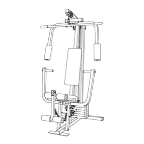
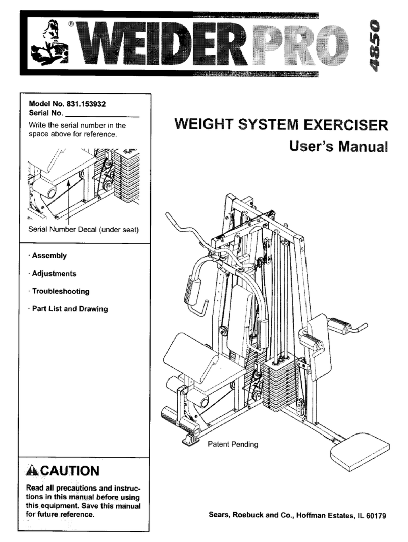
Weider 831.15393 User manual

ModelNo.831.153931
SerialNo.
Writetheserialnumberinthe
spaceaboveforreference.
SerialNumberDecal(underseat)
EXERCI-_E
E(_ UI PM ENT
ioigI =I,._ I IOI _I,;
HELPLINE!
!-800-736-6879
SEARS, ROEBUCK AND CO.
HOFFMAN ESTATES, IL 60179
_CAUTION
Read all precautions and instruc.
lions in this manual before using
this equipment. Save this manual
for future reference.
USER'S MANUAL
Patent Pending
._-'Vis_our websiteat_
www.weiderfitness.com
new products, prizes,
fitness tips, and much more!

TABLE OF CONTENTS
IMPORTANT PRECAUTIONS ............................................................. 3
BEFORE YOU BEGIN ................................................................... 4
ASSEMBLY ........................................................................... 5
ADJUSTMENTS ....................................................................... 22
WEIGHT RESISTANCE CHART ........................................................... 24
TROUBLESHOOTING .................................................................. 25
CABLE DIAGRAMS .................................................................... 26
ORDERING REPLACEMENT PARTS ................................................ BackCover
FULL 90 DAYWARRANTY ....................................................... Back Cover
Note: A PART IDENTIFICATION CHART and a PART LIST/EXPLODED DRAWING are attached in the center of
this manual. Remove the PART IDENTIFICATION CHART and the PART LIST/EXPLODED DRAWING before
beginningassembly.
2

IMPORTANT PRECAUTIONS
_WARNING: To .d.=. th. risk of serious infury, mad the following Important precautions
before using the Weight system.
1. Read oil inatructio_s In this manual and in 13, Always dlsconnect b'mlat bar from the
the au:ompanying IItondure before using the weight system when performing an exercise
weight system. _at does not use the/at bar.
2. It is the responsibility of the owner to ensure
that all users of the might system m ade-
quately Informed of all precautions,
3. The weight system is intended for home use
only. Do not use the welg_ system in any
commercial, rental, or instib_onal ea_itng.
4. Use the weight system only on alevel =mr.
face. Cover the floor beneath the weight sys-
tem to prntect the Itoor.
5. Make sure that all parts are properly tight-
ened each time you use the weight system.
Replace any wom parts Imm_
6. Keap childmn under 12 and pats away from
the weight system at all time&
7. Ksep hands and feat away from moving parts.
8. Always wear athletic shoes for foot protecllon;
9. Tbe weight syatem is dexlgned to support a
a maximum user weight of 300 pounds.
10. The weight syatm should not be used by
more than one person at a time.
11. Always stand on the foof plato when per.
forming an exercise that could cause the
weight system to tip.
12. Never mime the butterfly arms, leg lever,
squat arm, lat bar, row bar, or handis while
weights am raised. The weights will fail with
grset force.
14. Make sure that the cables remain on the pul-
isys at all tim_ If the cables bind whlis you
are exercising, stop immedlateiy and make
sure that the cables m on all of the pulleys.
r , % =
15. If you feel pain or dizzJness at =mytime while
exercising; stop Immediately and begin cool-
ing down.
15.Thewarningdecalssimwnhemhavebeen
placed on the weight system in the locations
shown on page 4. if a decal Is mimdng or
illegible, plemm call our toil-free HELPLINE at
' 1-800-736-6879, Monday through Sabaday,
7 a.m._untit 7 p.m, C4mbal Time, to order a
frea mptacement dacaL Place the de_d on
the walght syatsm in the location shown.
•Misuseofthisproduct
mayresult,nserious
injury
•Readuser'smanual
andfollow allwarnings
andoperatingmstruc-
honspriortouse.
• Do notallowchildren
onor aroundmachine.
•Replacelabelif
damaged,illegible,or
removed.
Decal 2
Decal 1
AWARN ING: Before beginning thls or sny exercise program, consult your physician. This
Is especially Important for parsons over the ago of 35 or persons with pre-existing health proMems,
Read all instructions before using. SEARS assumes no responsibility for personal Injury or property
damage sustained by or through the use of this product.

BEFORE YOU BEGIN
Thank you for selectingthe versatileWELDER®PRO
4850 weight system.The WELDER®PRO 4850 weight
system offers an impressivearray ofweight stations
designedto develop every majormuscle groupof the
body.Whether your goal isto tone your body,build
dramatic muscle size and strength,or improve your
cardiovascularsystem, the PRO 4850 weight system
willhelp you to achieve the specificresultsyou want.
For your benefit, read this manual carefully before
using the weight system. If you have additional
questions, please call our toll-free HELPLINE at
1-800-736-6879, Monday throughSaturday, 7 a.m.
until7 p.m. Central Time (excluding holidays).To help
us assistyou, please note the productmodel number
and sedal number before calling. The model numberis
831.153931. The serial number can be found on a
decal attached to the weight system (see the front
cover of this manualfor the locationofthe decal).
Before readingfurther, please review the drawing
below and familiarizeyourselfwith the partsthat are
labeled.
Lat Ba_
High Pulley Station
Swivel Carriage
Butterfly
WARNING ASSEMBLED
DECAL t DIMENSIONS:
Height: 81 in.
Width: 96 in.
Length: 57 in.
WARNING DECAL 2
(one on each side)
Backrest
Low Pulley Station
Cud Pad
Seat
Leg Level
WARNING
DECAL2
Squat Arm
Backrest
.AdjustmentKnob
uat Knee Rest
Weight Stack
4

ASSEMBLY
Make Assembly Easier
Evewthing in this manual is designedto
ensure that the weight system can be assem-
bledsuccessfullybyartjone.
Before beginning assembly, makoosureto
read the information on this page. This
brief Introduction will me you much more
time than It takeS to read it.
Assembly Requires Two Persons
For your convenienceand safety,assemble the
weight systemwith the helpof anotherperson.
Set Aside Enough Time
Due tothe many features ofthe weightsystem, the
assembly process will requireseveral hours. By
settingaside plentyof time and bydecidingto
make the task enjoyable, assemblywillgo smoothly.
Select a Location for the Weight System
Because of _tsweight and size, the weightsystem
shouldbe assembled in the locationwhere it wdlbe
used. Make sure thatthere isenough roomto walk
around theweight systemas you assemble it.
How to Unpack the Box
To make assembly easier,we have divided the
assembly process intofourstages. The small hard-
ware needed for each stage is packaged in sepa-
rate bags. Important: Wait until you begin each
stage to open the parts bag(s) for that stage.
Place all partsof the weight system in a cleared
area and remove the packing materials.Do not dis-
pose ofthe packingmatarialsuntJIassemblyiscom-
pleted
Make sure that you have the following tools:
• Two adjustablewrenches
• One standard scrawddver
•One philhpsscrewdriver
• One rubber mallet
•You w=llalso need grease or petroleumjelly, a
small amount ofsoapy water, and maskingtape
Note:Assemblywillbe more convenientifyou have
a socket set, a set ofopen-end or closed-end
wrenches, or a set ofratchet wrenches.
How to Identify Parts
To help you identify the small parts used in assembly,
a PART IDENTIFICATION CHART is included in the
center ofthis manual. Laythe charton the floorand
use it to easily identifyparts dudngeach assembly
step. Note: Some small parts may have been pre-
attached. If a part is not in the parts bag, check
to see if it has been pre-attached.
How to Orient Parts
As you assemble the weightsystem, make sure that
all parts are orientedexactly as shownin the draw-
rags.
Tightening Parts
Tighten all parts as you assemble them, unless
instructedto do otherwise.
Questions?
Ifyou have questionsafter readingthe assembly
instructions,please call our Customer Service
Departmenttoll-free at 1-800-736-6879, Monday
through Fdday,6 a.m. until6 p.m. MountainTime.
The Four Stages of the Assembly Process
Frame Assembly--You willbegin by assembling
the base and the updghtsthat form the skeletonof
the weight system
Arm Assembly--Dunng this stage, you will
assemble the arms and the leg lever.
Cable Assembly--Dudng this stage, you will
attach the cables and pulleysthatconnectthe
weightstationsto the weight stacks.
Seat Assembly--Dudng the final stage, you will
assemble the seat and the backrests.
5
FRAME ASSEMBLY I
1. Make sure that you unde_mnd a|! of the
infonmdion on page 5 before you begin
assembling the weight system.
Locate and open the parts bags labeled "FRAME
ASSEMBLY 1" and "FRAME ASSEMBLY 2."
Press a 2" Square Inner Cap (105) intothe open
end ofthe Long Base (120).
Inserteight5/16" x 2 112"Carriage Bolts(110) up
through the Long Base (120) and the Short Base (2)
as shown. Note: It may be helpful to place tape
over the heads of the Carriage Bolts to hold
them in place.
Attach the Short Base (2) to the Long Base (120)
with two 5/16" x 2 3/4" Bolts(85), the Long Frame
Plate (71), and two 5116"Nylon Locknuts(86).
2. Attach the Outer Cap (24) to the ShortBase (2)
withtwo #8 x 314"Screws (98).
Press two 2" x 3" Inner Caps (58) into the Foot
Plate (53). Attach the Foot Plate to the Long Base
(120) with two 5/16" x 2 112"Carnage Bolts(110)
and two 5/16" Nylon Locknuts(86)
3. Attach the tether on the Pin (112) to the Long Base
(120) with a #10 x 1"Screw (14).
Attach the four Knee Rest Bumpers (123) tothe
Squat Knee Rest (41) with four #10 x 1"Bcrews
(14) Attach the Squat Knee Rest to the Long Base
(120) with a 3/8" x 3 1/4" Bolt (96) and a 3/8" Nylon
Locknut(87) Do not overtightan the Nylon
Locknut; the Squat Knee Rest must be able to
pivot.
3
110
110
58
71 85
120
86
110
110 1
120
86
24
41
6

4. Press a 1 1/2" Square Inner Cap (67) intothe
squaretube on the ButterflyUpright(3).
Slidethe ButterflyUpright (3) ontothe two indicated
5/16" x 2 1/2"Carriage Bolts(110) in the Short Base
(2). Finger tighten a 5/16" Nylon Locknut (86) onto
each Cardage Bolt. Do not tighten the Nylon
Locknuts yet.
5. Press a 2"x3" Inner Cap (58) intothe top of the
Seat Upright (9). Attach the Leg Lever Bumper (77)
to the Seat Upright with a #10 x 1" Screw (14).
Slide the Seat Upright (9) onto the two indicated
5/16" x 2 1/2" Carriage Bolts (110) in the Short
Base (2). Finger tighten a 5/16" Nylon Locknut (86)
onto each Carriage Bolt. Do not tighten the Nylon
Locknuts yet.
6. Hold the Seat Frame (8) between the Seat Upright
(9) and the ButterflyUpright (3). Attach the Seat
Frame to the Seat Upright with two 5/16" x 3 3/4"
Bolts (92), two 5/16" Washers (90), and two 5/16"
Nylon Locknuts (86). Do not tighten the Nylon
Locknuts yet.
Attach the Seat Frame (8) to the ButterflyUpright
(3) with two 5/16" x 3 3/4" Bolts(92), two 5116"
Washers (90), and two 5/16" Nylon Locknuts (86).
Do not tighten the Nylon Locknuts yet.
7
5
14
58
77,
110

7,
8.
Press a 2"x 3" Inner Cap (58) intothe top of the
Squat Upright (4). Slide the Squat Upright onto the
two indicated 5/16" x 2 1/2" Carriage Bolts (110) in
the Long Base (120). Finger tighten a 5/16" Nylon
Locknut (86) onto each Carriage Bolt. Do not tight-
en the Nylon Locknuts yet,
Press a 2"x 3" Inner Cap (58) into the top of the
Swivel Upright (5). Slidethe Swivel Updght ontothe
two indicated 5/16" x 2 1/2" Cardage Bolts(110) in
the Long Base (120). Finger tighten a 5/16" Nylon
Locknut (86) onto each Carriage Bolt. Do not tight-
en the Nylon Locknuts yet.
Press two Swivel Bushings(66) into the Swivel
Carriage (46).
Tighten an Adjustment Handle (65) intothe Swivel
Carriage (46). Orient the Swivel Carriage as shown.
Slide the Carriage ontothe Swivel Upright(5) and
engage theAdjustment Handle intoan adjustment
hole in the Swivel Upright.
8
65 ¸
Adjustment
Hole "_.
58
120
66
86
?
8

9. Attach a Roller (39) and two 5/16" Washers (90)
between the indicatedset of holes in the Squat
Slider (38) with a 5/16" x 3 112"Bolt(94), two 5/16"
Washers (90), and a 5/16" Nylon Locknut(86) as
shown.
Assemble the other three Rollers (39) to the
Squat Slider (38) in the same manner,
10. Slide the Squat Slider (38) down ontothe Squat
Updght (4).
11. Insertthe ends oftwo Weight Guides(42) intothe
indicatedbracketonthe LongBase (120). Slide two
Weight Bumpers(49) ontothe Weight Guides.Next,
slideten Weights (44) ontothe WeightGuides. Make
sure that the Weights are turned so the grooved
sides of the Weights are facing downward,
Press a Weight Tube Bumper (48) intothe lower
end of a Weight Tube (43). Insert the Weight Tube
intothe centers of the Weights (44). Make sure
that the Weight Tube is turned as shown.
Lubricatethe two outer holes in a TopWeight (45).
Slide theTop Weight ontothe Weight Guides (42).
Make sure that the Top Weight is turned so the
grooved side is facing downward.
Apply a number "10" decal tothe TopWeight (45) in
the locationshown. Apply decals withthe numbers
20 through 110 to the ten Weights (44).
Assemble the other weight stack in the same
way,
10
39
3.- 6
90---_r_39
9

12. Attach theTop Frame (6) between the Squat Upright
(4) and the Swivel Upright (5) withfour 8/16" x 3 3/4"
Bolts (92), the two Short Frame Plates (52), and two
5116"Nylon Locknuts (86) as shown. Do not tighten
the Bolts and Locknuts yet.
Attach the four Weight Guides (42) to the TopFrame
(6) with two 3/8" x 6 112"Bolts(95) and two 318"
NylonLocknuts(87).
13. Press two 2"x 3" Inner Caps (58) intothe TopFrame
(6) and the ButterflyTopFrame (7).
Attach the Butterfly Top Frame (7) tothe Top Frame
(6) with two 5/16" x 2 314"Bolts(85), two 5/16"
Washers (90), and two 5/16" Nylon Locknuts(86).
Do not tighten the Locknute yet.
Attachthe ButterflyTop Frame (7) to the Butterfly
Upright (3) with two 5/16" x 3 3/4" Bolts(92), two
5/16" Washers (90), and two 5/16" Nylon Locknuts
(86).
Tighten all of the 5/16" Nylon Locknuts (86) and
3/8" Nylon Locknuts (87) used in steps 2-13.
14. Open the parts bag labeled "ARM ASSEMBLY."
Pressthree 1 112"x 2" Inner Caps (21) intothe Leg
Lever (10). Attach the Eyebolt (116) to the Leg
Lever with a 318"Washer (91) and a 3/8" Nylon
Jamnut (113).
Lubricatea 3/8" x 2 1/2" Bolt (18) with grease. Turn
the Leg Lever (10) so thatthe welded tab is on the
indicated side, and attach the Leg Lever to the Seat
Upright (9) with the Bolt and a 318"Nylon Locknut
(87). Do not overtighten the Nylon Locknut; the
Leg Lever must be able to pivot easily.
15. Press a 2"x 2 1/2" Inner Cap (125) intothe
Butterfly Frame (47). Attach the tethers on the two
"L"-pins w/Tether (60) to the ButterflyFrame with a
#8 x 3/4" Screw (98).
Lubricate a 3/8" x3" Bolt (107) with grease. Attach
the Butterfly Frame (47) to the ButterflyTop Frame
(7) with the Boltand a 3/8" Nylon Locknut(87). Do
not overtighten the Nylon Locknut; the Butterfly
Frame must be able to pivot easily.
12
r// 52
_L_ 9_ _'_g2
13
92____9 o
86< 58
85
58
14
21
87
21
116
15
21
10

16 Pressa 1 112"x 2" Inner Cap (21) intothe Right
ButterflyArm (26) Wet the lower end of the Arm with
soapy water Slidea LongPad (54) ontotheArm.
Slide two Nut Clips (108) ontoa PressHandle (27).
Attach the Press Handle to the RmghtButterflyArm
(26) withtwo 5/16"x 3/4" ButtonHead Screws (51)
Slidethe Long Pad (54) down so that the bottomms
flushwith the lowerend ofthe Arm. Pressa 1"
RoundInner Cap (29) intothe Press Handle Wet
the Press Handlewith soapy water Slide aLong
Handgnp (28) onto the Press Handle.
Lubricatea3/8" x2"Bolt (100) with grease Attach
aPivot Bracket (70) to the Right ButterflyArm (26)
withthe Bolt and a3/8" Nylon Jamnut (113). Do not
overtighten the Nylon Jamnut; the Pivot Bracket
must be able to pivot easily. Repeat this step
with the Left Butterfly Arm (25).
17. Lubncate a 3/8" x 3" ButtonHead Bolt (104) and
both s=desof two Plastic Washers (56) with grease.
Attach the Right ButterflyArm (26) to the Butterfly
Frame (47) with the Bolt, the two Plastic Washers,
two ButterflyCaps (57), two 3/8" Washers (91), and
a 3/8" Nylon Jamnut (113) as shown. Make sure
that the recessed sides of the Plastic Washers
are fitted over the welded bushing in the
Butterfly Arm. Do not overtighten the Nylon
Jarnnut; the Butterfly Arm must be able to pivot
easily.
Repeat this step with the Left Butterfly Arm (25).
CABLE ASSEMBLY
18 IMPORTANT: Refer to the Cable IdentiflcstJon
Chart on page 26 for help Identifying the
cables. Do not overtl_ the belts and
nuts attaching the pulleys. The pulleys must
be able to turn freely.
Locate and open the parts bags labeled "CABLE
ASSEMBLY" and "PULLEYS."
Lubncate the 3/8" x 7" Bolt(30) with grease. Attach
the Swivel Cage (76) to the Swivel Carnage (46)
with the Boltand a 3/8" Nylon Locknut(87).
Locate the Swivel High Cable (74), which is 126
112"long and has a ball on one end and a
threaded bolt on the other end. Wrap the Cable
arounda 3 1/2" Pulley (78) Attach two Pulleysto
the Swwel Cage (76) wrothtwo 318"x 1 3/4" Bolts
(93) and two 3/8" Nylon Locknuts(87).
16
17 104
26 56
\
57_
91J /25
113
18
11

19. Route the Swivel High Cable (74) throughthe Swivel
Upright(5) and over a 4 1/2" Pulley(119). Attachthe
Pulleyinsidethe Uprightwitha 3/8" x 2 3/4" Bolt
(101), two 3/8"Washers (91), two 1/2"Spacers(89),
and a 3/8" NylonLocknut(87).
Attach a 3/8" x 2 1/2"Bolt(18), two 3/8"Washers
(91), and a 3/8" Nylon Locknut (87) to the Swivel
Upright(5).
20. Remove the preattached 3 112"Pulleys (78) from
the Small Pulley Plates (31).
Wrap the Swivel High Cable (74) over a 3 1/2"
Pulley (78). Attach the Pulleyand a Cable Trap (68)
to the secondset of holesfrom the top of the Small
Pulley Plates (31) with a 3/8" x 2"Bolt (100) and a
3/8" Nylon Locknut(87). Make sure the Cable
Trap is turned to hold the Cable In the groove of
the Pulley.
21. Wrap the Swivel HighCable (74) over a 41/2"
Pulley (119). Attach the Pulleyinside ofthe indicat-
ed bracket on the Top Frame (6) with 3/8" x 1 3/4"
Bolt (93) and a 3/8" Nylon Locknut(87).
22. Lift the Weight Tube (43) and the TopWeight (45)
closesttothe Swivel Upright(5). Make sure thatthe
small pinon the Weight Tube is insideof the groove
under the TopWeight.
Insert aWeight Pin (50) intothestack ofWeights
(44). Place a 1/2"Washer (1) on top ofthe Weight
Tube (43). "13ghtena 1/2"Nut (118) halfway ontothe
end of the Swivel High Cable (74). Screwthe end of
the Cable two full turnsintotheWeightTube. Then,
tightenthe Nut againstthe 1/2"Washer.
23. Locate the Swivel Cable (17), which is 115 318"
long and has an eyelet on each end. Attach the
Cable inside the Top Frame (6) with a 5/16" x 2 1/2"
Bolt (59), two 5/16" Washers (90), and a 5/16"
Nylon Locknut(86).
19
20
21
22
23
5 91 18
91 "_ .__01
91---._ _
1./l g 74
31
31
119 74
118
50
44
59 90 86 ,,17
12

24. Remove the preattached 3 112" Pulleys (78) from
the Offset Double "U"-bracket (61).
Wrap the Swivel Cable (17) arounda 3 1/2" Pulley
(78). Attach the Pulley to the Offset Double "U"-
bracket (61) with a 3/8" x 1 3/4" Bolt(93) and a 3/8"
Nylon Locknut (87).
25. Wrap the Swivel Cable (17) arounda 3 1/2"Pulley
(78). Attach the Pulleyand a Cable Trap (68) to the
nextto bottomhole in the Small PulleyPlates (31)
with a 3/8" x 2" Bolt(100) and a 3/8" Nylon Locknut
(87). Make sure the Cable Trap Is tumed to hold
the Cable in the groove of the Pulley.
26. Wrap the Swivel Cable (17) around a 3 1/2" Pulley
(78). Attach the Pulley and a Cable Trap (68) tothe
bracket on the Swivel Upright (5) with a 3/8" x 2"
Bolt (100) and a 3/8" Nylon Locknut(87). Make
sure the Cable Trap Is turned to hold the Cable
in the groove of the Pulley.
27. Attach the end of the Swivel Cable (17) to the
bracket on the Swivel Carnage (46) with a 318"x 1"
Bolt (13) and a 3/8" Nylon Locknut(87).
28. Locate the Lat Cable (88), which is 89 1/4" long
and has a ball on one end and an eyelet on the
other. Routethe eyeletend of the Cable upthrough
the ButterflyTop Frame (7) and arounda 3 1/2"
Pulley(78).Attach the Pulleyinsideof theButterfly
TopFrame witha 3/8" x 2 3/4" Bolt(101), two 3/8"
Washers (91), two 1/2"Spacers (89), and a 3/8"
NylonLocknut(87).
24
25
26
27
28
87--._
87
13

29. Wrap the Lat Cable (88) around a3 1/2" Pulley
(78). Attach the Pulley and a Long Cable Trap (102)
to theTop Frame (6) with a 318"x 1 3/4" Bolt(93)
and a 3/8" NylonJamnut (113). Make sure the
Cable Trap Is turned to hold the Cable In the
groove of the Pulley.
30. Remove the preattached 3 112" Pulleys (78) from
the Pulley Plates (63).
Wrap the Lat Cable (88) arounda 3 1/2"Pulley
(78). Attach the Pulleyand a Cable Trap (68) to the
secondset of holesfrom the top of the Pulley
Plates (63) witha 3/8" x 2"Bolt (100) and a 3/8"
Nylon Locknut(87). Make sure the Cable Trap is
turned to hold the Cable in the groove of the
Pulley.
31. Attachthe end ofthe Lat Cable (88) inside ofthe
ButterflyTop Frame (7) with a 5/16" x 2 1/2" Bolt
(59), two 5/16" Washers (90), and a 5/16" Nylon
Locknut (86).
32. Locate the Butterfly Cable (69), which is the
shortest Cable, Attachthe Cable to the Pivot
Bracket (70) on the Left ButterflyArm (25) with a
5/16" x 1"Shoulder Bolt(103) and a 5/16" Nylon
Locknut(86).
33. Wrap the ButterflyCable (69) over a "V"-pulley(55).
Attach the Pulleyand a Long Cable Trap (102) to
the indicatedbracketon the ButterflyUpright(3)
with a 3/8" x 2 1/2" Bolt(18) and a 3/8" Nylon
Locknut(87). Make sure that the Long Cable
Trap is turned to hold the Cable In the groove of
the Pulley.
29
102
31 86-.=,_ 90
4
I I
90
86
[];_'_-_.70 103
_/'/IIi A\\E -25
102
14

34. Remove the preattached 3 1/2" Pulleys (78) from
the Double "U"-brackst (62).
Wrap the Butterfly Cable (69) under a 3 1/2" Pulley
(78). Attach the Pulley tothe Double "U"-bracket
(62) with a 3/8" x 1 3/4" Bolt(93) and a 3/8" Nylon
Locknut(87).
35. Wrap the Butterfly Cable (69) over a =_r'-pulley (55).
Attach the Pulleyand a Long Cable Trap (102) to
the other bracketon the ButterflyUpright(3) with a
3/8" x 2 1/2" Bolt(18) and a 3/8" Nylon Locknut
(87). Make sure that the Long Cable Trap is
turned to hold the Cable in the groove of the
Pulley.
36. Attach the ButterflyCable (69) to the Pivot Bracket
(70) on the Right ButterflyArm (26) with a 5/16" x 1"
Shoulder Bolt(103) and a 5/16" Nylon Locknut(86).
37. Locate the Lag Lever Cable (75), which is 98 1/2"
long and has an eyelet on one end and a thread-
ed pin on the other end. Routethe eyelet end of
the Cable through the Seat Upright (9) and attach it
to the tab on the Leg Lever (10) with a 5/16" x 1"
Shoulder Bolt (103) and a 5/16" Nylon Locknut(66).
38. Attach a 3 112"Pulley(78) inside ofthe Seat
Upright(9) with a 3/8" x 2 3/4" Bolt (101), two 3/8"
Washers (91), two 112"Spacers (89), and a 3/8"
Nylon Locknut(87), as shown.
35
36
37
38
86
103
91
89
J
//
Y
101
15

39. Route the Leg Lever Cable (75) under a 4 1/2"
Pulley (119). Attach the Pulley and a Large Cable
Trap (121) to the indicated side of the Butterfly
Updght (3) with a 3/8" x 3 3/4" Bolt(122), a 3/8"
Washer (91), and a 3/8" Nylon Jamnut (113). Make
sure that the Large Cable Trap is turned to hold
the Cable in the groove of the Pulley.
40. Wrap the Leg Lever Cable (75) over a 3 1/2" Pulley
(78). Attach the Pulley to the Double "U"-bracket
(62) with a 3/8" x 1 3/4" Bolt(93) and a 3/8" Nylon
Locknut(87).
41. Remove the preattached 3 1/2" Pulley (not
shown) from the "U"-brecket (64).
Attach the end of the Leg Lever Cable (75) to the
"U"-bracket (64) with a 1/4"Washer (97) and a 1/4"
Nylon Locknut (34). Note: Do not completely
tighten the Locknut; it should be threaded onto
the end of the Cable so that two threads show
past the Locknut (see inset drawing).
42. Locate the Swivel Low Cable (72), which is the
only remaining cable that has an eyelet on one
end and a ball on the other end. Route the eyelet
end of the Cable throughthe cage on the Long
Base (120) and throughthe Swivel Upright(5) as
shown.
Attach a3 1/2" Pulley (78) to the indicatedbracket
on the Long Base (120) with 3/8" x 1 3/4" Bolt (93)
and a 3/8" Nylon Locknut (87).
43. Wrap the Swivel Low Cable (72) under a 3 1/2"
Pulley (78). Attach the Pulleyto the indicated brack-
et on the Long Base (120) with a 3/8"x 1 3/4" Bolt
(93) and a 318"NylonLocknut(87).
42
43
113
75
93
16

44. Wrap the Swivel Low Cable (72) over a 3 1/2" Pulley
(78). Attach the Pulley to the Offset Double "U"-
bracket (61) with a 3/8" x 1 3/4" Bolt (93) and a 3/8"
Nylon Locknut (87).
45. Wrap the Swivel Low Cable (72) under a 3 1/2"
Pulley (78). Attachthe Pulleyto the indicatedbrack-
et on the Long Base (120) with a 3/8" x 13/4" Bolt
(93) and a 3/8" Nylon Locknut (87).
46. Route the Swivel Low Cable (72) under the indicat-
ed stack of Weights (44).
Wrap the Swivel Low Cable (72) under a 3 1/2"
Pulley (78). Attach the Pulley to the indicated brack-
et on the Long Base (120) with a 3/8" x 1 3/4" Bolt
(93) and a 3/8" Nylon Locknut (87).
47. Wrap the Swivel Low Cable (72) over a3 1/2"
Pulley (78). Attach the Pulleyand a Cable Trap (68)
between the indicatedholes inthe Pulley Plates
(63) with a 3/8" x 2" Bolt (100) and a 3/8" Nylon
Locknut (87). Make sure that the Cable Trap Is
turned to hold the Cable in the groove of the
Pulley.
48. Wrap the Swivel Low Cable (72) under a 3 1/2"
Pulley (78). Attach the Pulleyto the indicated brack-
et on the ShortBase (2) with a 3/8" x 1 3/4" Bolt
(93) and a 3/8" Nylon Locknut(87).
44
45
47
48
87
2
120
93
17

49. Wrap the Swivel Low Cable (72) over a 3 1/2"
Pulley (78). Attach the Pulley and a Cable Trap (68)
between the lower set of holes in the =U"-bracket
(64) with a 3/8" x 2" Bolt (100) and a 3/8" Nylon
Locknut (87). Make sure that the Cable Trap Is
turned to hold the Cable in the groove of the
Pulley.
50. Attach the end ofthe Swivel Low Cable (72) inside
of the Short Base (2) with a 5/16" x 2 1/2"Bolt(59),
two 5/16" Washers (90), and a 5/16" Nylon Locknut
(86).
51. Locate the Squat Cable (73), which Is the only
remaining cable. Attach the eyelet end of the
Cable inside ofthe Long Base (120) with a 5/16" x
2 1/2" Bolt(59), two 5/16" Washers (g0), and a
5/16" Nylon Locknut(86).
52. Wrap the Squat Cable (73) over a 3 1/2" Pulley
(78). Attach the Pulley, a Cable Trap (68), and two
3/4" Spacers (124) between the indicatedbrackets
on the Squat Slider (38) with a 3/8" x 3 1/4" Bolt
(96) and a 318"Nylon Jamnut (113). Make sure
that the Cable Trap is turned to hold the Cable
in the groove of the Pulley.
49
5O
2
59 9O
18

53. Wrap the Squat Cable (73) under a3 1/2"Pulley
(78). Attach the Pulley and aCable Trap tothe sec-
ondset of holesfrom the top in the indicatedbrack-
et on the Long Base (120) with a 3/8"x 2" Bolt
(100) and a 3/8" Nylon Locknut(87). Make sure
that the Cable Trap Is turned to hold the Cable
in the groove of the Pulley.
54. Wrap the Squat Cable (73) over a 4 1/2" Pulley
(119). Attach the Pulley to the indicatedbracket on
the Top Frame (6) with a 3/8" x 13/4" Bolt (93) and
a 3/8" Nylon Locknut (87).
55. Place a 1/2"Washer (1) ontop of the Weight Tube
(43) closestto the Squat Upright(4). Tighten a 1/2"
Nut (118) halfway onto the end of the Squat Cable
(73).
Lift the Weight Tube (43) and the Top Weight (45)
and make sure that the small pin on the Weight
Tube is inside of the groove under the Top Weight.
Hold the Weight Tube (43) and the TopWeight (45)
a few inches over the weightstack and insertthe
Weight Pin (50). Screw theend ofthe Cable (73)
twofull turnsintotheWeight Tube. Then, tightenthe
Nut againstthe 1/2"Washer (1). Remove the Weight
Pin and set the TopWeight backon the weight
stack. Replace the Pin.
56. Locate and open the parts bag labeled "SEAT
ASSEMBLY."
Insertthe Pad Tube (23) intothe square holein the
Seat Upright(9). Slide the two Knee Pads (19) onto
the Pad Tube as shown. Press the two Knee Pad
Caps (109) intothe ends ofthe Pad Tube.
Slide two Short Pads (20) onto the Leg Lever (10).
100 120
87
19
73
56
1
20 10 109
19

57. Attach the Seat (16) to the Seat Frame (8) withtwo
114"x 3/4" Screws (114), a 1/4"x 2 1/2" Screw (99),
and e 1/4" Washer (97).
58. Attachthe ButterflyBackrest(15) to the Butterfly
Upright(3) with four 1/4" x3/4" Screws (114).
59. Wet one end of the Squat Arm (32) with soapy
water. Slide aShort Pad (20) onto the Squat Arm
as shown.
Slide two Nut Clips (108) onto a Squat Handle (33).
Attach the Squat Handle to the Squat Arm (32) with
two 5/16" x 3/4" Button Head Screws (51). Slide an
Inner Cap w/Hole (111) onto the Squat Handle and
press it onto the end of the Squat Arm. Wet the
Squat Handle with soapy water. Slide an 8"
Handgrip(84) onto the Squat Handle.
Repeat this step with the other end of the Squat
Arm (32).
60. Attach the SquatArm (32) tothe Squat Bracket (37)
withtwo 3/8" x 2 1/2" Carriage Bolts(106) and two
3/8" Nylon Locknuts(87). Do not tighten the
Nylon Locknuts yet.
Finish attachingthe Squat Arm (32) to the Squat
Bracket (37) with two 3/8" x 3" Carriage Bolts(126),
a Small SupportPlate (127), and two 3/8" Nylon
Locknuts(87).
Tighten ell of the 318"Nylon Locknuts (67) used
in this step.
57
58
15-
2O
..2O
\51
111
84
6O
106
2O
Table of contents
Other Weider Fitness Equipment manuals

Weider
Weider PRO 4300 User manual

Weider
Weider WEBE35560 User manual

Weider
Weider Pro Pt 800 Bench User manual

Weider
Weider Pro 7500 User manual

Weider
Weider Pro 9725 User manual

Weider
Weider Viper 2000 User guide

Weider
Weider SPARRING SYSTEM User manual

Weider
Weider 136-2 Bench User manual

Weider
Weider Pro 9510 User manual

Weider
Weider 2990 I User guide

Weider
Weider Pro 9545 User manual

Weider
Weider 130 User manual

Weider
Weider Pro 9450 User guide

Weider
Weider WEBE1996.0 User manual

Weider
Weider C133 User manual

Weider
Weider WEBE26780 User manual

Weider
Weider 1012 Flex Home Gym User manual

Weider
Weider FLEX XT2 User manual

Weider
Weider 132 Training User manual

Weider
Weider Wesy70072powermax User manual