CONTENTS
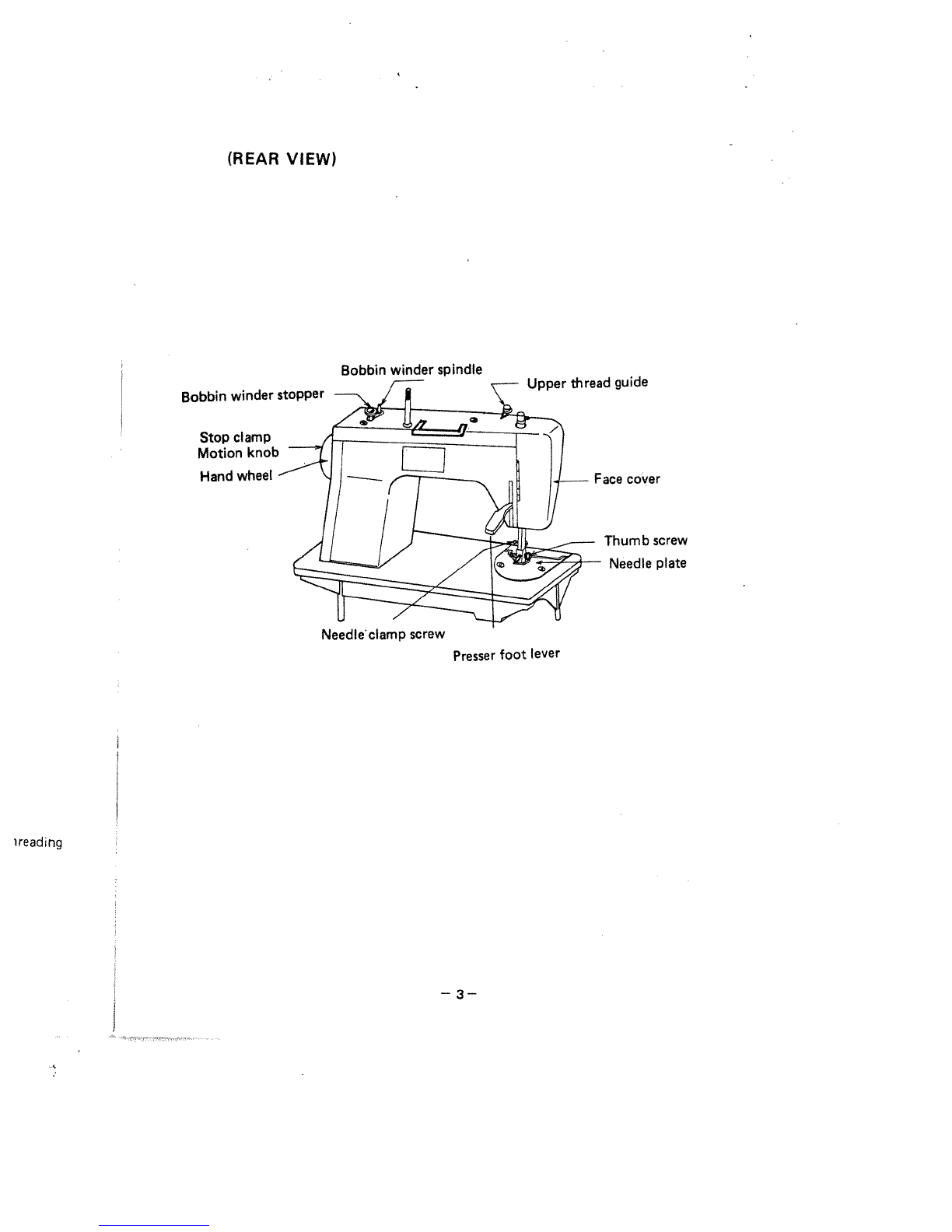
Name of
Parts.........,.,,,..,,............
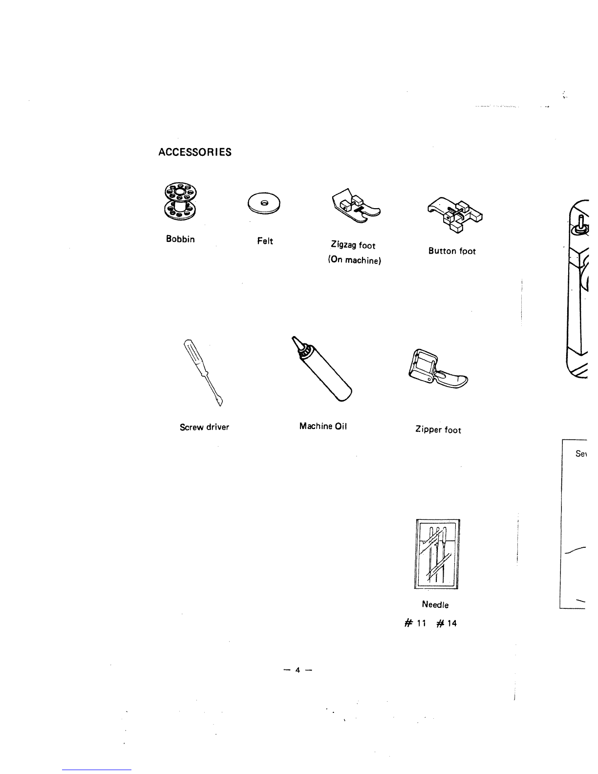
Accessories
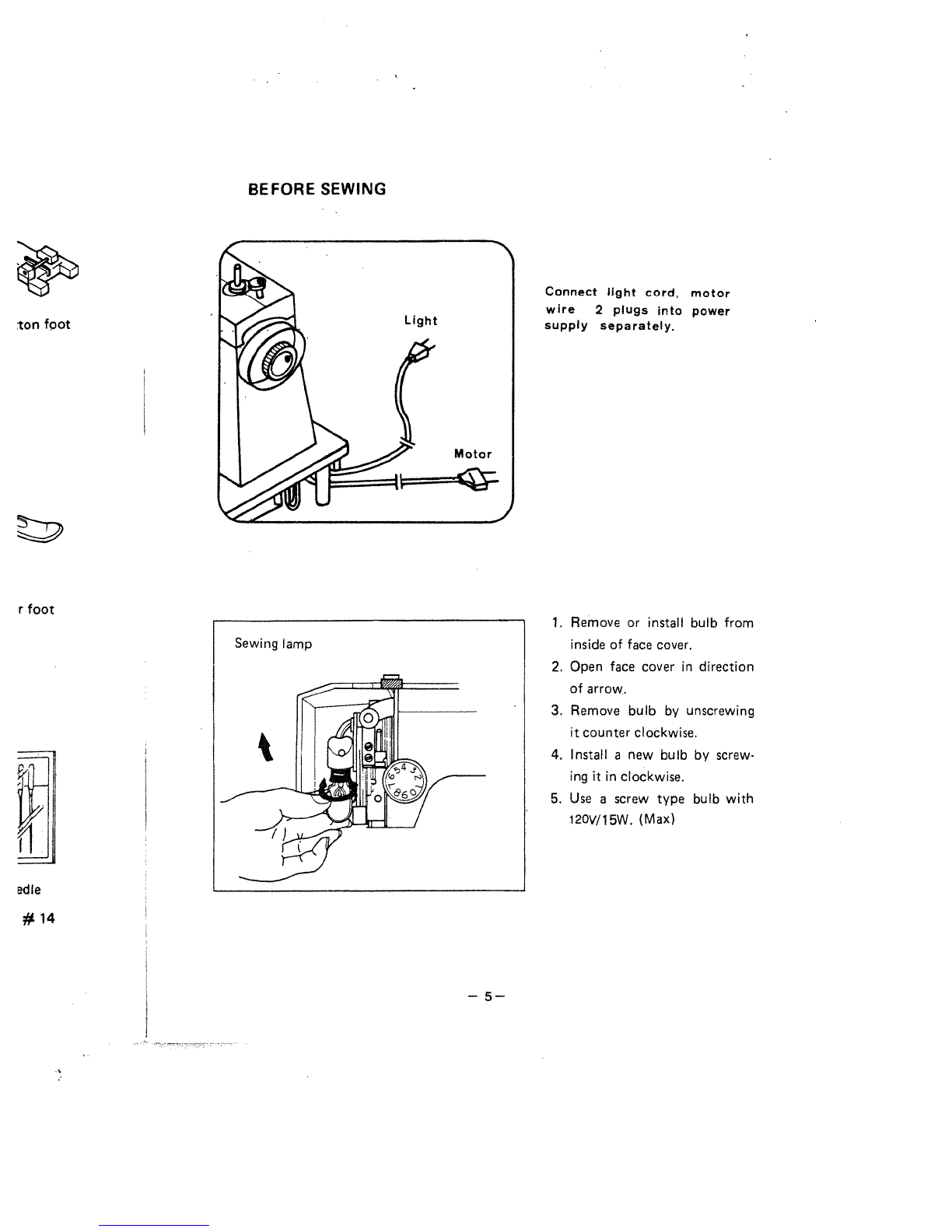
Before
sewing
(Power
supply
and Sewing
lamp)
Winding
the
bobbin
Removing
bobbin
case
and
bobbin
Inserting bobbin
into bobbin
case
Inserting bobbin
case
into
shuttle
race
Threading
upper
thread
&
Twin
needle
threading.
Drawing
up
bobbin
thread
Changing
sewing
directions.
Contr&
dial
&
Adjusting
thread tension.
Regulating the
presser
foot
pressure
Drop
feed
Changing
needle
.
Fabric.
Thread.
Needle
table
Sewing
(pattern
selector)
and
operation
table
To
start
sewing
To
finish
seam
Straight
stitch
Zigzag
sewing
Blind
stitch
Button
sewing
Binding
Zipper
sewing
Hemming
Twin
Needle
Embroidery
Quilter
Seam
guide
Maintenance
(Cle.3ning
and
oiling)
Checking
Performance
Problems
WHAT
TO DO
2&3
4
5
6
7
7
9
10
10
11&12
13
13
14
15
16
17
18
19
19
20&21
22
22
23
24
25
25
26
26
27
28
Head
in
ne
set
screws
is
clear.
gues
up
and
ill
go.
to
bead
hinges
ues
are
inser
.n
go
into
head
est
in
its
tilted
Drews
securely
5
into
sockets
et.
Cord
inden
tag
must
be
cket marked
cord
goes
to
8
—
1—•