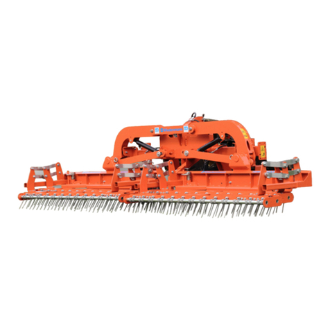
Wiedenmann Terra Rake 170 Wiring diagram

Translation of original
Operating Instructions
Verticutting harrow
Terra Rake 170
521.001
From equipment I.D. No. :
Status :
April 2017
521 99 01

All information, illustrations and specifications in these Operating Instructions are based on the latest information available at the time of
publication. We reserve the right to make design changes at any time without prior notification
2
EC DECLARATION OF CONFORMITY
We
Wiedenmann GmbH
Am Bahnhof
89192 Rammingen
declare under our sole responsibility that the product
Verticutting harrow
Terra Rake 170
to which this declaration refers, corresponds with the relevant basic safety and health
requirements of the machinery directive 2006/42/EC.
Rammingen, the 10.03.2015
Horst Wiedenmann
(Place and date of issue)
Managing Partner
(Name, function and signature of
authorised person)
Rammingen, the 10.04.2017
Markus Remmele
(Place and date of issue)
Technical office manager Authorised
representative for tech.
documentation
(Name, function and signature of
authorised person)
NOTE: The declaration of conformity is no longer valid if changes are made to
the machine that have not been agreed with the manufacturer.

All information, illustrations and specifications in these Operating Instructions are based on the latest information available at the time of
publication. We reserve the right to make design changes at any time without prior notification
3
Declaration of conformity
We
Wiedenmann GmbH
Am Bahnhof
89192 Rammingen
hereby declare that the product
Verticutting harrow
Terra Rake 170
referred to by this declaration complies with the requirements of
Machinery Directive 2006/42/EC.
Rammingen, the 10.03.2015
Karl Wiedenmann
(Place and date of issue)
Sales Manager
(Name, function and signature of
authorised person)
Rammingen, the 10.03.2015
Harald Reuen
(Place and date of issue)
Operations Manager
(Name, function and signature of
authorised person)
Wiedenmann GmbH
Am Bahnhof
D 89192 Rammingen
Tel. No. : +49 (0) 7345 / 953-0
Fax No. : +49 (0) 7345 / 953 233
Internet : http://www.wiedenmann.de

All information, illustrations and specifications in these Operating Instructions are based on the latest information available at the time of
publication. We reserve the right to make design changes at any time without prior notification
4
Preface
READ THESE OPERATING INSTRUCTIONS CAREFULLY to familiarise yourself with the
correct way to operate and service your machine, and to prevent personal
injury or damage to the machine.
These operating instructions and the adhesive safety signs on your machine
can also be obtained in other languages
(your dealer can order these for you).
THESE OPERATING INSTRUCTIONS ARE a permanent part of your machine and should
be handed over to the new owner if the machine is sold.
MEASUREMENTS in these operating instructions are given in the metric system.
Only use suitable parts and screws. Different wrenches are required for
metric and inch screws.
"LEFT" are based on the forward direction of travel of the mounted equipment
or attached machine.
ENTER THE PRODUCT IDENTIFICATION NUMBERS in the appropriate “Technical data”
or “Product - Identification Number” sections. Please ensure that all
figures are accurately entered. These numbers can be of invaluable
assistance for tracing the machine should it be stolen. Your dealer also
needs these numbers when you order spare parts. We recommend that you
additionally file these identification numbers in a secure place away from
the machine.
BEFORE DELIVERY OF THIS MACHINE, your dealer performed a pre-delivery
inspection to ensure optimal performance.
THE VERTICUT HARROW IS DESIGNED SOLELY for commercial use and for
conventional use on artificial turf surfaces used for sports grounds for
the digging and roughing up of the ground surface, as well as for the
removal of thatch.
It is also used on artificial turf surfaces to loosen the filling material.
The "strain relief kit" extra equipment must be fitted to the machine where
it is used on artificial turf surfaces ("SPECIFIED USE").
Usage for any other purpose beyond this is considered as contrary to the
intended use. The manufacturer accepts no liability for damage or injury
resulting from this improper use. These risks are borne solely by the user.
Compliance with and strict adherence to the operating, maintenance and
repair conditions as specified by the manufacturer also form essential
elements of the intended usage.
VORHERSEHBARER FEHLGEBRAUCH/MISSBRAUCH. Es darf kein Transport von Personen
und Gegenstände mit dem angebauten oder angehängten Gerät vorgenommen
werden.
THIS MACHINE MUST ONLY BE operated, maintained and repaired by persons
familiar with all its particular characteristics and acquainted with the
relevant safety regulations. The relevant accident prevention regulations,
all other generally recognised safety-related, occupational medicine and
road traffic regulations must be adhered to. Any modifications carried out
to this machine without the express approval of the manufacturer excludes
the manufacturer of all liability for any resulting damage.

All information, illustrations and specifications in these Operating Instructions are based on the latest information available at the time of
publication. We reserve the right to make design changes at any time without prior notification
5
TABLE OF CO N T E N T S Page
* * * * * * * * * * * * * * * * * * * * * * * * * * * * * * * * * * * * * * * * * * * * * * * * * * *
1.0. Safety................................................. 6-12
1.1. Safety Decals.................................. 11
1.2. Safety Equipment............................... 12
2.0. Assembly............................................... 13-16
2.1. General Information............................ 13
2.2. Fitting the three-point frame.................. 13
2.3. Electric connection to battery................. 13
2.4. Fitting the drawbar............................ 14
2.5. Mounting the strain relief kit................. 15+16
3.0. Transport.............................................. 17+18
3.1. General Information............................ 17
3.2. Transportation of the Terra Rake............... 17
3.3. Transportation with the Terra Rake............. 18
4.0. Connecting to the Tractor.............................. 19+20
4.1. General Information............................ 19
4.2. Mounting with cat.1............................ 19
4.3. Mounting with cat.0............................ 20
4.4. Mounting with drawbar.......................... 20
5.0. Disconnecting from the Tractor......................... 21
5.1. General Information............................ 21
5.2. Removing the Terra Rake........................ 21
6.0. Before Initial Operation............................... 22+23
6.1. General Information............................ 22
6.2. Depth adjustment............................... 22
6.3. Setting the strain relief kit.................. 23
7.0. Operation.............................................. 24+25
7.1. General Information............................ 24
7.2. Driving characteristics........................ 24
7.3. Adjusting the working depth.................... 25
8.0. Maintenance............................................ 26-28
8.1. General Information............................ 26
8.2. Lubricating –General information.............. 27
8.3. Lubricating points............................. 27
8.4. Cleaning the verticut harrow................... 28
8.5. Replacing the spring tines..................... 29
8.6. Disassembly/Disposal........................... 30
8.7. Unauthorised Modification
and Spare Part Manufacturing......................... 31
9.0. Equipment.............................................. 32-33
9.1. Scope of Delivery.............................. 32
9.2. Machine designs................................ 32
9.3. Special equipment.............................. 33
9.4. Attachment components.......................... 33
10.0. Technical Specifications............................... 34-37
10.1. Technical Data................................. 34+35
10.2. Metric bolt and cap screw torque values........ 36
10.3. Chassis Number................................. 37

All information, illustrations and specifications in these Operating Instructions are based on the latest information available at the time of
publication. We reserve the right to make design changes at any time without prior notification
6
1.0. Safety
Recognize safety information
This is the safety-alert
symbol. When you see this
symbol on your machine or in
this manual, be alert to the
potential for personal injury.
Follow recommended precautions
and safe operating practices.
Follow safety instuctions
Carefully read all safety
messages in this manual and on
your machine safety sings. Keep
safety sings in good condition.
Replace missing or damaged
safety sings. Be sure new
equipment components and repair
pqarts include the curret
safety sings. Replacement
safety sings are available from
your dealer.
Learn how to operate the
machine and to use controls
properly. Do not let anyone
operate without instruction.
Keep your machine in proper
working condition. Unauthorized
modifications to the machine
may impair the fuction and/or
safety and afect machine life.
If you do not understand any
part of this manual and need
assistance, contact your
dealer.

All information, illustrations and specifications in these Operating Instructions are based on the latest information available at the time of
publication. We reserve the right to make design changes at any time without prior notification
7
1.0. Safety
Observe road traffic regulations
Always observe llocal road
traffic regulations when using
public roads.
Wear protective clothing
Wear close fitting clothing and
safety equipment appropriate to
the job.
Prolonged exposure to loud noise
can cause impairment or loss of
hearing.
Wear a suitable hearing
protective device such as
earmuffs or earplugs to protect
against objectionable or
uncomfortable loud noises.
Operating equipment safety
requires the full attention of
the operator. Deo not wear radio
or music headphones while
operating machine.
Stay clear of rotating drivelines
Entanglement in rotating
driveline can cause serious
injury or death.
Keep tractor master shield and
driveline shields in place at
all times. Make sure rotating
shields turn freely.
Keep tractor master shield and
driveline shields in place at
all times. Make sure rotating
shields turn freely.

All information, illustrations and specifications in these Operating Instructions are based on the latest information available at the time of
publication. We reserve the right to make design changes at any time without prior notification
8
1.0. Safety
Guard and shields
Keep guards and shields in place
all the times. Ensure that they
are in good condition and installed
correctly.
Always disengage the driveline, shut
off engine and remove key before
removing any guards or shields.
Keep hands, feet and clothing away
from moving parts.
Avoid high - pressure fluids
Escaping fluid under pressure
can penetrate the skin causing
serious injury.
Avoid the hazard by relieving
pressure before disconnecting
hydraulic or other lines.
Tighten all connections before
applying pressure.
Search for leaks with a piece
of cardboard. Protect hands and
body from high pressure fluids.
If an accident occurs, see a
doctor immediately. Any fluid
injected into the skin must be
surgically removed within a few
hours or gangrene may result.
Doctors unfamiliar with this
type of injury should reference
a knowledgeable medical source.

All information, illustrations and specifications in these Operating Instructions are based on the latest information available at the time of
publication. We reserve the right to make design changes at any time without prior notification
9
1.0. Safety
Use safety lights and devices
Prevent collisions between
other road users, slow moving
tractors with attachments or
towed equipment, and self-
propelled machines on public
roads. Frequently check for
traffic from the rear,
especially in turns, and use
hand signals or turn signal
lights.
Use headlights, flashing
warning lights, and turn
signals day and night. Follow
local regulations for equipment
lighting and marking. Keep
lighting and marking visible
and in good working order.
Replace or repair lighting and
marking that has been damaged
or lost. An implement safety
lighting kit is available from
your dealer.
Avoid heating near pressurized fluid lines
Flammable spray can be
generated by heating near
pressurized fluid lines,
resulting in severe burns to
yourself and bystanders. Do not
heat by welding, soldering,
using a torch near pressurized
fluid lines or other flammable
materials. Pressurized lines
can be accidentally cut when
heat goes beyond the immediate
flamme area.

All information, illustrations and specifications in these Operating Instructions are based on the latest information available at the time of
publication. We reserve the right to make design changes at any time without prior notification
10
1.0. Safety
Remove paint before welding or heating
Avoid potentially toxic fumes
and dust.
Hazardous fumes can be
generated when paint is heated
by welding, soldering, or using
a torch.
Do all work outside or in a
well ventilated area. Dispose
of paint and solvent properly.
Remove paint before welding or
heatingh:
If you sand or grind paint,
avoid breathing the dust.
Wear an approved respirator.
If you use solvent or paint
stipper with soap and water
before welding. Remove
solvent or paint stripper
containers and other
flammable material from area.
Allow fumes to disperse at
least 15 minutes before
welding or heating.

All information, illustrations and specifications in these Operating Instructions are based on the latest information available at the time of
publication. We reserve the right to make design changes at any time without prior notification
11
1.0. Safety
1.1. Safety Decals
Pictorial safety sings
At several important places of
this machine safety sings are
affixed intendent to signify
potenial danger. The hazard is
identified by a pictorial in a
warning triangle. An adjacent
pictorial provides information
how to avoid personal injury.
These safety sings, their
placement on the nachine and a
brief explanatory text are
shown below.
Operator’s manual
This operator’s manual
contains all important
information necessary for
safe machine operation.
Carefully observe all
safety rules to avoid
accidents.
Service
Before performing service
or repair work, turn off
engine and remove key.
521.01
521.02

All information, illustrations and specifications in these Operating Instructions are based on the latest information available at the time of
publication. We reserve the right to make design changes at any time without prior notification
12
1.0. Safety
1.2. Safety instructions
Apart from the information in
these operating instructions,
please also observe generally
applicable safety and accident-
prevention standards!
During work operation, the user
is responsible for the safety
of third parties!
During operation on public
highways, the relevant traffic
regulations must be observed!
Before moving off, ensure that
the immediate area of the
machine is clear e.g. no
children nearby.
Ensure that your visibility is
not impaired.
Keep clear of the danger zone
of the machine!
Always ensure there is
sufficient front-axle load; the
steering capability of the
vehicle must be maintained.
Observe the max. permissible
axle load of the tractor.
The driving and operational
characteristics of the tractor
may be influenced by the
attachment of the Terra Rake.
Always adapt your driving style
to match the terrain and ground
conditions.
Special care should be taken
when working and turning on a
slope.

All information, illustrations and specifications in these Operating Instructions are based on the latest information available at the time of
publication. We reserve the right to make design changes at any time without prior notification
13
2.0. Assembly
2.1. General Information
Only attach the machine on
firm, even ground.
The Terra Rake is secured to
the pallet by two transport
feet when delivered. Once
removed, the transport feet are
no longer required and can be
disposed of.
For this work, please use your
personal protective equipment
(PSA) such as: gloves, goggles,
ear protectors.
2.2. Fitting the three-point frame
Securely bolt the three-point
frame (A) onto the appropriate
hole pattern using five hexagon
bolts (B).
2.3. Electric connection to battery
Only appropriately qualified
professionals may carry out the
connection work.
Electrical connection is
necessary for supplying the
electrospindle with electric
power.
See the accompanying
instructions for the
installation description.

All information, illustrations and specifications in these Operating Instructions are based on the latest information available at the time of
publication. We reserve the right to make design changes at any time without prior notification
14
2.0. Assembly
2.4. Installing the drawbar
Securely bolt the drawbar (A)
to the bracket (B) on the basic
unit using the three bolts (C).
Secure the bracket (D) of the
electrospindle (E) to the basic
unit frame using the bolt (F).
NOTE:
Electro spindle (A) must NOT be
energised.
Secure the cable to the drawbar
using the fastening clamps (G).
Install the electric cable with
rocker switch (H) and plug (J)
to the tractor.
Connect the plug (J) to the
appropriate socket.
For the trailer version, the
sensing wheels must be secured
in place. To do this, the
bracket (L) is bolted to the
pivot bracket (K) as shown in
Fig. 521.07.

All information, illustrations and specifications in these Operating Instructions are based on the latest information available at the time of
publication. We reserve the right to make design changes at any time without prior notification
15
2.0. Assembly
2.5. Mounting the strain relief kit
ATTENTION DANGER!
The machine shall be set down on
an even, secure surface for the
mounting of the strain relief kit.
Remove the screw, spring circlip
and washer. The removed washer
will be replaced.
Secure spring holder I (A) on
right with washer, spring
circlip and screw as shown in
figure 521.28.
Secure spring holder II (B) on
right with washer, spring
circlip and screw as shown in
figure 521.29.

All information, illustrations and specifications in these Operating Instructions are based on the latest information available at the time of
publication. We reserve the right to make design changes at any time without prior notification
16
2.0. Assembly
2.5. Mounting the strain relief kit
ATTENTION DANGER!
The machine shall be set down on
an even, secure surface for the
mounting of the strain relief kit.
Remove the screw, spring circlip
and nut. The removed washer will
be replaced.
Secure the tension spring with
long eye bolt (C) from the
outside, instead of the removed
screw on the right, with washer,
spring circlip and screw
(see figure 521.31).
Secure the tension spring with
short eye bolt (D) from the
inside, instead of the removed
screw on the right, with washer,
spring circlip and screw
(see figure 521.32).
The adjustment process is
described in section 6.3.

All information, illustrations and specifications in these Operating Instructions are based on the latest information available at the time of
publication. We reserve the right to make design changes at any time without prior notification
17
3.0. Transport
3.1. General Information
The Terra Rake is delivered
secured to a transport frame.
Use only forklift trucks and
lifting equipment with a
sufficient load bearing
capacity.
Never stand under lifted
loads. There is an imminent
danger to life if the load
falls.
Improper transport and
assembly of the Terra Rake
can:
- injury to persons
- damage to property.
3.2. Transportation of the Terra Rake
Caution must be excercised when
cutting through the securing
straps. Risk of injury due to
ends “springing open”.
Transport Using a Forklift
If the Terra Rake is still
secured on the transport
frame:
Insert the forks under the
transport frame (pay attention to
the direction of approach),
carefully lift the transport
frame,
unload the Terra Rake from the
transport device,
cut through the securing straps,
NOTE:
After unpacking, check that
all parts for the Terra Rake
are present.
The shipping company and
Wiedenmann GmbH or the delivery
company must be notified
immediately in writing of any
transportation damage and missing
parts.

All information, illustrations and specifications in these Operating Instructions are based on the latest information available at the time of
publication. We reserve the right to make design changes at any time without prior notification
18
3.0. Transport
3.3. Transportation with the Terra Rake
3.3.1. Version with three-point linkage
Raise the attached equipment
with the tractor rear hydraulic
system and secure against
inadvertent lowering.
3.3.2. Version with drawbar
Fully retract the electrospindle
piston rod by activating the
rocker switch.
This ensures that the attached
machine is angled forwards and
the harrows are lifted off the
ground.
CAUTION !
The equipment version with a
drawbar is NOT approved for
travel on public roads!
3.3.3. Parking and loading safety
When parking the machine or
transporting it on a trailer,
slide the parking stands (A) on
both sides into the frame (B) and
secure with the pin (C).

All information, illustrations and specifications in these Operating Instructions are based on the latest information available at the time of
publication. We reserve the right to make design changes at any time without prior notification
19
4.0. Connecting to the Tractor
4.1. General Information
CAUTION DANGER!
Secure the tractor against
rolling away.
Switch off the tractor and
secure it against inadvertent
switching on.
4.2. Mounting with cat.1
Mount the lower guide bolt on
the outside in the lowest
possible location bore.
You thus achieve a maximum lift
travel.
1. Mount lower guide to
bolt (A) and secure with
linch pin.
2. In the case of rear
hydraulics of tractors
with float position:
insert upper guide
with bolt (B) into bore
hole (C) on three-point
frame and secure with
linch pin.
In the case of rear
hydraulics of tractors
without float position:
insert upper guide with
bolt (B) into slotted
hole (D) on three-point
frame and secure with
linch pin.
Adjust the upper guide so
that the bolt is located
in the middle of the
slotted hole in the
working position.
3. Tighten turnbuckles (5) of
the stabilisation chain.

All information, illustrations and specifications in these Operating Instructions are based on the latest information available at the time of
publication. We reserve the right to make design changes at any time without prior notification
20
4.0. Connecting to the Tractor
4.3. Mounting with cat.0
Mount the lower guide bolt on
the inside in the lowest
possible location bore.
You thus achieve a maximum lift
travel.
1. Mount lower guide to
bolt (A) and secure with
linch pin.
2. In the case of rear
hydraulics of tractors with
float position: insert
upper guide with bolt (B)
into bore hole (C) on
three-point frame and
secure with linch pin.
In the case of rear
hydraulics of tractors
without float position:
insert upper guide with
bolt (B) into slotted hole
(D) on three-point frame
and secure with linch pin.
Adjust the upper guide so
that the bolt is located in
the middle of the slotted
hole in the working
position.
3. Tighten turnbuckles of the
stabilisation chain.
4.4. Mounting with drawbar
Insert the drawbar on the
tractor and secure it.
Lay the electric cable with
rocker switch and plug to the
tractor.
Connect the plug to the
matching three-pin socket.
Table of contents
Other Wiedenmann Farm Equipment manuals

Wiedenmann
Wiedenmann Terra Float Air User manual

Wiedenmann
Wiedenmann Terra Spike XF 20-6 User manual

Wiedenmann
Wiedenmann Terra Rake 460 Wiring diagram

Wiedenmann
Wiedenmann Terra Clean 100 Wiring diagram

Wiedenmann
Wiedenmann Super 600 Wiring diagram

Wiedenmann
Wiedenmann TERRA GROOM Wiring diagram

Wiedenmann
Wiedenmann Super 600 Wiring diagram
Popular Farm Equipment manuals by other brands

Agria
Agria 8100 215 Translation of the original operating instructions

Jula
Jula 729-028 operating instructions

TATU
TATU LTA 3000 instruction manual

EASY COOPS
EASY COOPS 5x6 Chicken Coop Plan manual

Hisarlar
Hisarlar SB1150 User and maintenance manual

Headsight
Headsight CORN GERINGHOFF RD installation manual