manuals.online logo
Brands
  1. Home
  2. •
  3. Brands
  4. •
  5. Wieland
  6. •
  7. Control Unit
  8. •
  9. Wieland gesis FLEX-0/2W DC F User manual

Wieland gesis FLEX-0/2W DC F User manual

Montag
e
Installat
i
g
es
i
2-fach J
2-fold s
h
Doc. #
B
Nur El
e
Ausfü
h
Gerät
n
Gerät
n
Die ei
n
Lande
s
Der DC-J
montierb
die Busv
e
Der umf
a
IEC 6153
Hinweis:
Program
m
Bedien-
u

Tas
t

Tas
t

Tas
t

LED
LED

LED

Ras
t

Jalo

DC-
E

Sic
h
Montag
e
Schritt 1:
1.1
Endk
1.2
Zusa
t
hörb
a
1.3
Endk
Schritt 2:
2.1
An j
e
2.2
Mod
u
2.3
An j
e
Die
M
Schritt 3:
3.1
Am
M
3.2
Kabe
Wic
h
3.3
Bei
M
Technis
c
Netzans
c
Netzvers
o
A
usgän
g
Bemessu
Bemessu
Absicher
u
Umwelt
b
Einsatzb
e
Klimabes
Umgebu
n
Lagerte
m
Montag
e
Gehäus
e
Material
Farbe
Brandver
Brandlas
t
Abmess
u
Elektris
c
Schutzkl
a
Schutzar
t
Verschm
u
Überspa
n
Zulassu
n
CE-Kenn
z
Handbu
c
mit detai
l
Wartung
:
Doku
m
Downl
o
http://
e
e
anleitung (Original
)
i
on Instructions (Tr
a
i
sFLEX-0/2W
a
lousieausgang mit
h
utter output with f
u
B
A000998 - 05/2
0
e
ktrofachkräfte dür
f
h
rung müssen sie d
i
n
icht öffnen. Keine
n
ur in spannungsfr
e
n
schlägigen Norme
n
s
sind zu beachten.
alousieausgang 2-f
a
a
ren AP-Gehäuse z
u
e
rsorgung vom vor
g
a
ngreiche Paramete
r
5
steckbaren elektri
Funktionstests dir
e
m
ierung möglich.
u
nd Funktionsele
m
t
er 'select' Wähl
Der
g
t
er ▼Ta
s
Ta
s
t
er ▲Ta
s
Ta
s
'1'
'2'
Sign
a
▲:F
a
▼: F
a
'status' Sign
a
Gr
ü
Ro
t
t
fuß Arret
usieausgang 2
A
(M
o
E
inspeisung An
s
ant
h
erung T6,3A W
e
5x
2
e
(siehe Rückseite,
Module Stecken
appe links auf Basi
s
t
zmodule in gewün
s
a
rem Klick einraste
n
appe auf letztes M
o
Optional: Befesti
g
dem Modul mit Sc
h
u
le auf Tragschiene
dem Modul mit Sc
h
M
odule sind auf der
Kabel stecken un
d
M
odul die Kabel

l an allen weiteren
M
h
tig: Festen Sitz alle
M
ontagerahmen: Ka
b
c
he Daten
c
hluss
o
rgung AC
g
e
ngsspannung
ngsstrom
u
ng
b
edingungen
e
reich
tändigkeit
n
gstemperatur
m
peratur
e
art
e
halten
t
u
ngen (B, H, L)
c
he Sicherheit
a
sse
t
u
tzungsgrad
n
nungskategorie
n
gen
z
eichnung
c
h
lierten Information
e
:
entnummer: BA00
0
o
ad über QR-Code
o
e
shop.wieland-electri
c
)
a
nslation based on
O
DC F
Sicherung (83.0
2
u
se (83.02
0
15 (Rev. A)
G
E
f
en dieses Gerät ins
t
iese Anleitung gele
s
Fremdobjekte einfü
e
iem Zustand ansch
n
, Richtlinien, Vors
c
a
ch 24 VDC/3 A mit
u
m dezentralen Ein
b
g
eschalteten Modul
.
r
satz ermöglicht ve
r
schen Verbindung
e
e
kt nach Montage
m
m
ente (siehe Rück
s
t einen Jalousieaus
g
g
ewählte Ausgang
b
s
tendruck > 500ms:
s
tendruck < 500ms:
s
tendruck > 500ms:
s
tendruck < 500ms:
a
lisiert die Fahrricht
u
a
hrbewegung aufw
ä
a
hrbewegung abwä
a
lisiert den Betriebs
z
ü
n: Modul funktion
s
t
: Fehlermeldung
ierung für Montage
A
nschlüsse für Stec
k
o
ntage: siehe Rück
s
s
chluss der Versorg
t
riebe mit Stecker G
e
chselbare Sicherun
2
0mm träge 6,3A.
Abbildung 2)
s
modul setzen und
e
s
chter Reihenfolge
r
n
.
o
dul rechts aufsetze
g
ung auf Tragschi
e
h
raubendreher den
R
aufsetzen.
h
raubendreher den
R
Tragschiene befest
i
d
sichern
stecken.
M
odulen stecken (S
r Steckverbindung
e
bel mit Kabelbinder
230 VAC, -15 % /
+
5 bis 24V DC (Ver
s
3 A je Kanal
6 A als Summenst
r
6,3 A T (träge in D
C
Innenräume und tr
Klasse 3K5 (EN 50
4
-5 °C bis +45 °C
-25 °C bis +75 °C
Decken-, Boden-,
W
ebene Fläche, Tra
g
Kunststoff, haloge
n
Lichtgrau, ähnlich
UL94 V-2
ca. 1,72 kWh
95*
)
mm, 149 mm,
I
IP20 (nach EN 605
2
2
III
Gemäß EMV-Richt
Erfüllt Normen: E
N
e
n zu Programmier
u
0
903
o
der:
c.com/product/83.0
2
D
E
O
riginal Documenta
t
2
0.0637.0)
0.0637.0)
E
FAHR
t
allieren und in Bet
r
s
en und verstanden
hren. Gerät von Wa
ließen oder trennen
c
hriften und Bestim
m
Sicherung im flach
b
au, wird vom Basi
s
.
Die 24 VDC-Verso
r
r
schiedene Automa
t
e
n trennen Automat
i
m
it der Vorortbedien
s
eite,
A
bbildung 1
)
g
ang.
b
eginnt zu blinken.
Fährt Jalousie nac
h
Lamellenbewegun
g
Fährt Jalousie nac
h
Lamellenbewegun
g
u
ng und den Status
ä
rts
rts
z
ustand des Erweit
e
s
bereit (kein Fehler).
auf Tragschiene /
M
k
er GST15i2 lichtbla
s
eite, Abbildung 3)
ungsspannung 5 bi
ST15i2 lichtblau (91
g zur Absicherung
b
e
inrasten.
r
echts an das Basis
m
n und einrasten.
e
ne oder Montage
r
R
astfuß nach oben
z
R
astfuß nach unten
i
gt.
iehe: Montageanlei
t
e
n sicherstellen.
n am Montagerah
m
+
10 %, 50/60 Hz (fü
r
s
orgung über extern
r
om beider Ausgän
g
C
-Zuleitung)
ockene Räume, we
t
4
91-2)
W
andmontage, fest
e
g
schiene TH35-7,5,
M
n
frei
RAL 7035 / Schwar
z
46 mm
*
2
9)
linie und Niederspa
N
50491-5-1, EN 50
4
u
ng, Inbetriebnahm
e
2
0.0637.0
E
t
ion)
ge
r
ieb nehmen. Vor
haben.
sser und Feuer fern
.
m
ungen des jeweili
g
e
n, auf Tragschien
e
s
modul verwaltet u
n
r
gung erfolgt von e
x
t
ionsfunktionen. Di
e
i
on und Installation.
ung an den Geräte
n
h
unten.
g
oder Stopp
h
oben.
g
oder Stopp
der Jalousiebeweg
e
rungsmoduls.
M
ontagerahmen
u (91.921.3353.0)
s
24 VDC für die Ja
l
.922.3353.0)
b
eider Kanäle. Sich
e
m
odul setzen und
m
r
ahmen
z
iehen.
drücken.
t
ungen).
m
en befestigen.
r
Folgemodule)
es Netzteil)
g
e
t
tergeschützt
e
Installation, Aufp
u
M
ontagerahmen
z
, ähnlich RAL 900
5
*
)
105mm
mit Endkappe
n
nungsrichtlinie
4
91-5-2, EN 50491-
5
e
und
Wielan
Brenn
e
96052
Tel.:
+
Fax:
+
Intern
e
Email:
e
si
s
FLEX-0/2W
D
n
halten.
g
en
e
n
d erhält
x
tern.
e
nach
n
ohne
ung.
lousie-
e
rung
m
it
u
tz, auf
5
e
rechts
5
-3

Onl
y
und
e
Do
n
wat
e
Onl
y
The
to b
e
The 2-
f
on car
r
bus po
param
e
plugga
Note:
F
tion an
Opera
t

's
e

B
u

B
u

L
E
L
E

L
E

R
e

S
h

D
C

F
u
Install
a
Step 1
:
1.1
Pl
a
1.2
Pl
a
it i
n
1.3
Pl
a
Step 2
:
2.1
Pu
2.2
Se
t
2.3
Pr
e
Th
e
Step 3
:
3.1
Pl
u
3.2
Pl
u
Im
3.3
Fo
r
Techn
i
Mains
Mains
s
Outpu
t
Rated
v
Rated
c
Fuse p
r
Enviro
Area o
f
Climat
e
Ambie
n
Storag
e
Type
o
Housi
n
Materi
a
Colour
Reacti
o
Fire lo
a
Dimen
s
Electri
c
Protec
t
Protec
t
Conta
m
Over-v
o
A
ppro
v
CE ma
r
Hand
b
with d
e
nance:
Doc
u
Dow
http:
/
d Electric GmbH
e
rstraße 10-14
Bamberg
+
49 (951) 9324-0
+
49 (951) 9324-198
e
t: www.wieland-el
e
info@wieland-elect
r
D
C F
y
trained electrician
s
e
rstood this instruc
t
n
ot open the device
e
r and fire.
y
connect or discon
n
relevant standards,
e
observed.
f
old DC shutter out
p
r
ier rails for decentr
a
w
er from the upstr
e
e
ter set enables diff
e
ble in accordance
w
F
unction tests direc
t
d without program
m
t
ing and functiona
l
e
lect' button Se
l
Th
e
u
tton ▼

P

P
u
tton ▲

P

P
E
D '1'
E
D '2'
Si
g
m
e
▲:
▼:
E
D 'status' Si
g

G

R
e
sting foot Lo
c
h
utter output

2
(
C
power feed

C
p
u
se T6,3A

R
6
a
tion (see back pa
g
:
Plugging in mod
u
a
ce the end cap on
t
a
ce the additional m
n
to place with an a
u
a
ce the end cap on
t
:
Optional: Fasteni
n
l
l the resting foot o
n
t
the modules onto
t
e
ss the resting foot
o
e
modules are now
Plugging in cable
u
g in cable

to th
e
u
g in cables at all ot
h
portant: Ensure th
a
r
mounting frames:
i
cal Data
connection
s
upply AC
t
s
v
oltage
c
urrent
r
otection
n
mental condition
f
application
e
resistance
n
t temperature
e
temperature
o
f installation
n
g
a
l
o
n to fire
a
d
s
ions (W, H, L)
c
al safet
y
t
ion class
t
ion type
m
ination level
o
ltage category
v
als
r
king
b
ook
e
tailed information
o
u
ment number: BA
0
nload via QR code
o
/
/eshop.wieland-ele
c
e
ctric.com
ic.com
D
s
may install and co
m
t
ion manual before
t
.
Do not insert any
f
n
ect the device if it
h
directives, regulati
o
p
ut 24 VDC/3 A wit
h
a
lised installation, is
e
am module. The 2
4
e
rent automation fu
w
ith IEC 61535, sep
a
t
ly after installation
m
ing.
l
elements (see ba
c
ects one shutter ou
e
selected output b
e
P
ressing the button
P
ressing the button
P
ressing the button
P
ressing the button
g
nals the movement
e
nt.
Movement upward
Movement downw
g
nals the operating
s
G
reen: Module read
y
R
ed: Fault message
c
king mechanism f
o
2
connections for pl
u
I
nstallation: see ba
c
C
onnection of powe
p
lug GST15i2 light b
R
eplaceable fuse for
6
.3A.
g
e, Figure 2)
u
les
he left of the base
m
o
dule in the desire
d
u
dible click.
he last module on t
n
g on carrier rail o
r
n
every module up
w
t
he carrier rail.
o
n every module d
o
f
astened on the car
s
and securing th
e
e
module.
h
er modules (see: i
n
t all plug-in connec
t
fix to mounting fra
m
230 VAC, -15 %
/
5 to 24V DC (po
w
3 A per channel
6 A as a total cu
r
6.3 A T (slow in
D
s
Internal rooms a
n
Class 3K5 (EN 5
0
-5 °C to +45 °C
-25 °C to +75 °C
Installation on c
e
mounted, on lev
e
Plastic, halogen-
f
Light grey, simil
a
UL94 V-2
approx. 2 kWh
95*
)
mm, 149 m
m
I
IP20 (in accorda
n
2
III
In accordance w
Meets standards
o
n programming, c
o
00904
o
r:
tric.com/product/83
.
D
ANGER
mmission this devi
c
t
hey carry out insta
l
f
oreign objects. Ke
e
has been de-energi
s
o
ns and provisions
o
h
fuse in the flat AP
s
administered by t
h
4
VDC power suppl
y
u
nctions. The electri
c
a
rate automation a
n
are possible on the
c
k page, figure 1)
u
tput.
e
gins to flash.
> 500ms: Moves t
h
< 500ms: lamella
m
> 500ms: Moves t
h
< 500ms: lamella
m
t
direction and the
s
d
s
w
ards
s
tatus of the extens
y
to function (no fa
u
o
r installing on carri
e
ug GST15i2 light bl
u
c
k page, Figure 3)
e
r supply 5 to 24 V
D
b
lue (91.922.3353.0
)
r
protecting both ch
m
odule and latch it
d
order on the right
o
t
he right and latch i
t
r mounting frame
w
ards with a screw
d
o
wnward with a scr
e
r
rier rail.
e
m
n
stallation instructi
o
tions are securely s
e
m
e with cable bind
e
/ +10 %, 50/60 Hz (
w
er supply through
r
rent for both outp
u
DC feed line)
nd dry rooms, prot
e
0
491-2)
e
iling, floor and wal
l
el surface, carrier r
a
-
free
a
r to RAL 7035 / Bl
a
m, 46 mm
*
n
ce with EN 60529)
w
ith EMC Directive a
s
: EN 50491-5-1, E
N
o
mmissioning and
m
.020.0637.0
EN
c
e. They must have
lation.
p the device away
f
s
ed.
o
f the particular co
u
housing, which ca
n
h
e base module and
y
is external. The ex
t
c
al connections, w
h
n
d installation.
devices with on-sit
e
h
e shutter downwar
d
m
ovement or stop
h
e shutter upwards.
m
ovement or stop
s
tatus of the shutter
ion module.
u
lt).
e
r rail / mounting fr
a
u
e (91.921.3353.0)
C for the shutter dr
i
)
annels. Fuse 5x20
m
into place.
o
f the base module
t
into place.
river.
e
wdriver.
o
ns).
e
ated.
e
rs.
for the subsequent
external power so
u
u
ts
e
cted from weather
l
, fixed installation,
s
a
il TH35-7.5, mount
i
a
ck, similar to RAL
9
*
)
105 mm with right en
d
nd Low Voltage Dir
50491-5-2, EN 50
4
m
ainte-
DE/EN 1
read and
f
rom
u
ntry are
n
be fitted
receives
t
ensive
h
ich are
e
opera-
d
s.
move-
a
me
i
ve with
m
m slow
and latch
modules)
u
rce)
s
urface-
i
ng frame
9
005
d
cap
ective
4
91-5-3
Montag
e
Installat
i
g
es
i
2-fach J
2-fold s
h
Doc. #
B
A
bbild
u
Figure
1
A
bbild
u
Figure
2
A
bbild
u
Figure
3
e
anleitung (Original
)
i
on Instructions (Tr
a
i
sFLEX-0/2W
a
lousieausgang mit
h
utter output with f
u
B
A000998 - 05/2
0
u
ng 1: Bedien- und
1
: Operating and f
u
u
ng 2: Montage
2
: Installation
u
ng 3: Montage de
3
: Installation of t
h
)
a
nslation based on
O
DC F
Sicherung (83.0
2
u
se (83.02
0
15 (Rev. A)
Funktionselemen
t
u
nctional element
s
r Stecker
h
e plugs
GST15i2 (91.922
.
O
riginal Documenta
t
2
0.0637.0)
0.0637.0)
t
e
s
.
3353.0 und/and 91
t
ion)
ge
.
921.3353.0)
Wielan
Brenn
e
96052
Tel.:
+
Fax:
+
Intern
e
Email:
e
si
s
FLEX-0/2W
D
d Electric GmbH
e
rstraße 10-14
Bamberg
+
49 (951) 9324-0
+
49 (951) 9324-198
e
t: www.wieland-el
e
info@wieland-elect
r
D
C F
e
ctric.com
ic.com
Drehmoment
Torque
0,5 … 0,7 Nm
4,4 … 6,2 lb-in
DE/EN 2
Instructi
Istruzio
n
g
es
i
Sortie d
e
Uscita v
Doc. #
B
Seuls
l
servic
e
Ne pa
s
feu.
Ne ra
c
Respe
c
pays.
Le modu
l
monter s
u
obtient s
o
Le bloc d
électriqu
e
Remarq
u
comman
d
Élément
s

Bou
t

Bou
t

Bou
t

LED
LED

LED
'sta
t

Pie
d

Sor
t

Ali
m

Fusi
Montag
e
Étape 1 :
1.1
Mon
t
1.2
Mon
t
les e
n
1.3
Mon
t
Étape 2 :
2.1
Tirer
2.2
Plac
e
2.3
Pous
Les
m
Étape 3 :
3.1
Racc
o
3.2
Racc
o
Imp
o
3.3
Avec
Caractér
Raccord
e
Tension
s
Sorties
Tension
n
Intensité
Fusible r
e
Conditio
Zones d'
u
Résistan
c
ment
Tempéra
t
Tempéra
t
Type de
Boîtier
Matériau
Couleur
Comport
e
Charge d
Dimensi
o
Sécurité
Classe d
e
Indice de
Degré d'
e
Catégori
e
Homolo
g
Marquag
Notice
compren
a
service e
t
Numér
o
Téléch
a
http://
e
ons de montage (T
r
n
i per il montaggio (
T
i
sFLEX-0/2W
e
store 2 postes
e
neziana a 2 canali
B
A000998 - 05/2
0
l
es électriciens spé
c
e
. Avant de comme
n
s
ouvrir l'appareil. N
c
corder l'appareil ou
c
ter les normes, dir
e
l
e de store à 2 sorti
e
u
r barres de suppor
o
n alimentation de
b
e paramètres comp
e
s enfichables selo
n
u
e : les tests de fon
c
d
e sur site des app
a
s
de commande e
t
t
on 'select' Sé
La
t
on ▼
A

A
t
on ▲
A

A
'1'
'2'
Si
g
▲
▼
t
us'
Si
g

V

R
d
encliquetable Ar
r
t
ie de store 
2
(
m
entation CC 
R
f
(
ble T6,3 A 
f
5
e
(voir verso, figur
e
Enfichage du mo
d
t
er le capuchon d'e
x
t
er les modules sup
p
n
cliqueter jusqu'à e
n
t
er le capuchon d'e
x
En option : fixatio
n
le pied encliquetabl
e
r les modules sur l
e
s
er le pied enclique
t
m
odules sont fixés
s
Enfichage du câbl
o
rder les câbles

o
rder le câble à tou
s
o
rtant : s'assurer de
cadre de montage
istiques techniqu
e
e
ment secteur
s
ecteur CA
n
ominale
nominale
e
commandé
n
s ambiantes
u
tilisation
c
e à l'environne-
t
ure ambiante
t
ure de stockage
montage
e
ment au feu
'incendie
o
ns (l, H, L)
électrique
e
protection
protection
e
ncrassement
e
de surtension
g
ations
e
CE
a
nt des information
s
t
maintenance :
o
de document : B
A
a
rgement via code
Q
e
shop.wieland-electri
c
r
aduction de la noti
c
T
raduzione delle ist
r
DC
(83.020.0637.0)
(83.020.0637.0)
0
15 (Rev. A)
D
A
c
ialisés sont autoris
é
n
cer, ils doivent av
o
e pas insérer d'obj
e
ne le déconnecter
q
e
ctives, prescriptio
n
e
s 24 VDC/3 A avec
r
t pour un montage
b
us du mode présél
p
let permet différent
n
CEI 61535 sépare
n
c
tionnement sont p
o
a
reil
t
de fonction (voir
v
lectionne la sortie
d
sortie sélectionnée
A
ppui sur le bouton
A
ppui sur le bouton
A
ppui sur le bouton
A
ppui sur le bouton
g
nale le sens de dé
p
:déplacement vers
: déplacement vers
g
nale l'état de fonct
V
ert : module prêt à
R
ouge : message d'
r
êt pour le montag
e
2
raccordements p
o
(
91.921.3353.0) (M
o
R
accordement de la
f
onctionnement du
s
(
91.922.3353.0)
f
usible remplaçable
5
x 20 mm à action
e
2)
d
ule
x
trémité sur le côté
p
lémentaires dans l
n
tendre un clic.
x
trémité sur le côté
n sur un rail porte
u
e vers le haut sur c
h
e
rail porteur.
t
able vers le bas à l'
s
ur le rail porteur.
e et fixation
sur le module.
s
les autres module
s
la bonne fixation d
e
: fixer les câbles su
r
e
s
230 VCA, -15 % / +
5 à 24 VCC (alimen
t
3 A par canal
6 A en tant somme
6,3 A T (à retardem
Espaces intérieurs
e
es
Classe 3K5 (EN 50
4
de -5 °C à +45 °C
de -25 °C à +75 °C
Montage au plafon
d
sur une surface pla
n
Matière plastique,
s
gris clair, similaire
à
UL94 V-2
env. 2 kWh
95*
)
mm, 149 mm,
4
d'extrémité à droite
I
IP20 (selon EN 605
2
2
III
Conformément à la
Conforme aux nor
m
5-3
s détaillées sur la p
r
A
000904
Q
R ou :
c.com/product/83.0
2
F
R
c
e originale)
r
uzioni originali)
A
NGER
é
s à installer cet ap
p
o
ir lu et compris ces
e
ts tiers. Tenir l'app
a
q
ue lorsqu'il n'est
p
n
s et dispositions a
p
fusible se trouvant
décentralisé est gé
r
ectionné. L'aliment
a
es fonctions d'auto
m
n
t l'automatisation
e
o
ssibles directeme
n
v
erso, figure 1)
d
e store.
commence à clign
o
> 500 ms : le store
< 500 ms : les lam
e
> 500 ms : le store
< 500 ms : les lam
e
p
lacement et l'état
d
le haut
le bas
ionnement du mod
u
fonctionner (pas d'
erreur
e
sur rail porteur / c
a
o
ur le connecteur G
S
o
ntage : voir verso,
f
tension d'alimenta
t
s
tore avec le conne
c
pour la protection
d
retardée 6,3 A.
gauche du module
'ordre souhaité à dr
droit du dernier mo
u
r ou un cadre de
h
aque module à l'ai
d
aide d'un tournevis
s
(voir : instruction
s
e
tous les raccords
e
r
le cadre de monta
g
10 %, 50/60 Hz (po
u
t
ation via un bloc d'
de l'intensité des d
e
ent pour l'alimentat
e
t locaux secs, prot
é
4
91-2)
d
, au sol et au mur
;
n
e, rail porteur TH3
5
s
ans halogène
à
RAL 7035 / noir, s
i
4
6 mm
*
)
2
9)
directive CEM et B
a
m
es : EN 50491-5-1,
r
ogrammation, mis
e
2
0.0637.0
R
ge
p
areil et à le mettre
e
instructions.
a
reil éloigné de l'ea
u
as sous tension.
p
plicables dans cha
q
dans un boîtier AP
r
é par le module de
a
tion 24 VCC est ex
t
m
atisation. Les rac
c
e
t l'installation.
t après le montage
o
ter.
descend.
e
lles bougent ou Ar
r
monte.
e
lles bougent ou Ar
r
d
u mouvement de s
t
u
le d'extension.
erreur).
a
dre de montage
S
T15i2 bleu clair
f
igure 3)
t
ion de 5 à 24 VCC
p
c
teur GST15i2 bleu
d
es deux canaux. F
u
d
e base et l'encliqu
e
oite du module de
b
d
ule et l'encliquete
r
m
ontage
d
e d'un tournevis.
sur chaque modul
e
de montage).
e
nfichés.
g
e à l'aide de serre-
c
u
r les modules suiv
a
alimentation extern
e
ux sorties
ion CC)
é
gés contre les inte
m
installation fixe, en
5
-7,5, cadre de mo
n
milaire à RAL 9005
105 mm
avec capucho
n
a
sse tension
EN 50491-5-2, EN
5
e
en
Wielan
Brenn
e
96052
Tel.:
+
Fax:
+
Intern
e
Email:
e
si
s
FLEX-0/2W
D
en
u
et du
q
ue
plat à
base et
terne.
c
ords
avec la
rêt
rêt
t
ore.
pour le
clair
u
sible
eter.
b
ase et
r
.
e
.
câbles.
a
nts)
e)
m
péri-
n
saillie,
n
tage
n
50491-

L'in
s
escl
u
pri
m
Non
da a
Coll
e
Ris
p
L'uscit
a
portan
t
dal mo
param
e
elettric
Nota:
è
locale
p
Eleme
n

T
a

T
a

T
a

L
E
L
E

L
E
's
t

Pi

U
s

A
l

F
u
Mont
a
Passo
1
1.1
In
s
1.2
In
s
av
v
1.3
Ap
Passo
2
2.1
Su
2.2
Po
s
2.3
Su
I
m
Punto
3
3.1
In
s
3.2
In
s
Im
3.3
In
c
Dati t
e
Colleg
a
Alime
n
Uscite
Tensio
n
Corren
t
Protezi
Condi
z
Camp
o
Resist
e
ci
Tempe
Tempe
Tipo d
i
Custo
d
Materi
a
Colore
Resist
e
Carico
Dimen
s
Sicure
z
Classe
Grado
d
Grado
d
Categ
o
Omol
o
Marchi
Manu
a
con inf
manut
e
Doc
u
Dow
http:
/
d Electric GmbH
e
rstraße 10-14
Bamberg
+
49 (951) 9324-0
+
49 (951) 9324-198
e
t: www.wieland-el
e
info@wieland-elect
r
D
C F
s
tallazione e la mes
s
u
sivamente da elett
m
a di effettuare qual
s
aprire l'apparecchi
o
cqua e fuoco.
e
gare o scollegare l
'
p
ettare le norme, dir
e
a
relè a 2 strati 24
V
t
e per installazione
d
dulo inserito a mon
t
e
tri impostabili con
s
i a innesto a norma
è
possibile eseguire
p
resente sugli appa
r
n
ti di comando e f
u
a
sto 'select'
C
L
a
sto ▼


a
sto ▲


E
D '1'
E
D '2'
S
E
D
t
atus'
S


edino di fissaggio
D
t
s
cita veneziana

l
imentazione DC

u
sibile T6,3A

ggio (vedere a ter
g
1
:inserimento dei
s
erire il cappuccio t
e
s
erire gli altri moduli
v
ertire il "clic" che i
n
plicare il cappuccio
2
:opzionale: fissa
g
ogni modulo spost
a
s
izionare i moduli s
u
ogni modulo prem
e
m
oduli sono ora fiss
a
3
:inserimento e fi
s
s
erire il cavo

sul
m
s
erire i cavi in tutti g
portante: assicurar
s
c
aso di montaggio
s
e
cnici
a
mento di rete
n
tazione di rete AC
n
e nominale
t
e nominale
one consigliata
z
ioni ambientali
o
d'impiego
e
nza ai fattori climat
ratura ambiente
ratura di stoccaggi
o
i
montaggio
d
ia
a
le
e
nza al fuoco
comburente
s
ioni (LxHxL)
z
za elettrica
di protezione
d
i protezione
d
'inquinamento
o
ria di sovratension
e
o
gazioni
o CE
a
le
ormazioni dettaglia
t
e
nzione:
u
mento numero: B
A
nload mediante co
d
/
/eshop.wieland-ele
c
e
ctric.com
ic.com
P
s
a in servizio di que
s
r
otecnici. che devo
n
s
iasi operazione.
o
. Non introdurre o
g
apparecchio solo i
n
e
ttive, prescrizioni
e
V
DC/3 A con fusibile
d
ecentrata, è gestit
a
t
e. L'alimentazione
2
ente di realizzare di
v
IEC 61535 separan
o
la verifica delle fun
z
r
ecchi senza progra
m
u
nzionali (vedere
a
C
onsente di selezio
n
L
'uscita selezionata

Premendo il tasto

Pressione del tast
o

Premendo il tasto

Pressione del tast
o
S
egnala la direzion
e
▲
:Movimento vers
o
▼
: Movimento vers
o
S
egnala le condizio
n

Verde: modulo pr
o

Rosso: segnalazio
D
ispositivo di fissag
t
elaio di montaggio

2 collegamenti pe
(montaggio: vede
r

Collegamento del
l
l'azionamento ve
n
(91.922.3353.0)

fusibile sostituibil
e
5 x 20 mm inerte
6
g
o, figura 2
moduli
e
rminale a sinistra s
u
nella sequenza des
n
dica l'avvenuto blo
terminale sull'ultim
g
gio su guida di s
u
a
re il piedino di fiss
a
u
lla guida di suppor
t
e
re il piedino di fiss
a
a
ti alla guida di sup
p
s
saggio dei cavi
m
odulo.
li altri moduli (vede
r
s
i che tutti i connett
s
u telaio: fissare i c
a
230 VAC, -15 %
/
da 5 d 24V DC (
a
3 A per canale
6 A come corren
6,3 A T (con fusi
b
In ambienti inter
n
i
-Classe 3K5 (EN
5
da -5 °C a +45 °
C
o
da -25 °C a +75
°
A soffitto, pavim
superficie piana,
gio
PVC, senza alog
e
Grigio chiaro, si
m
UL94 V-2
ca. 2 kWh
95*
)
mm, 149 m
m
i
IP20 (secondo E
N
2
e
III
Secondo la Diret
Conforme alle n
o
5-3
t
e sulla programma
z
000904
ice QR o:
tric.com/product/83
.
ERICOLO
s
to apparecchio de
v
n
o aver letto e com
p
g
getti estranei. Ma
n
n
assenza di tension
e
disposizioni in vig
o
e
, con alloggiament
o
a
dal modulo base
e
24 VDC proviene d
a
verse funzioni di au
o
automazione e in
s
z
ioni subito dopo l'i
mmazione.
a
tergo la figura 1)
n
are un'uscita vene
z
inizia a lampeggiar
e
per > 500ms, si ab
t
o < 500ms: movim
e
per > 500ms, si al
z
t
o < 500ms: movim
e
e
e lo stato del movi
o l'alto
o il basso
n
i di esercizio del m
o
nto per l'uso (nes
s
o
ne di errore
g
gio per l'installazio
n
e
r connettore GST1
5
re a tergo, figura 3)
la tensione di alime
n
eziana con connet
t
e
per la protezione
d
6,3A.
u
l modulo base.
s
iderata a destra del
o
ccaggio.
m
o modulo a destra.
u
pporto o telaio di
a
ggio verso l'alto c
o
to.
a
ggio verso il basso
p
orto.
r
e le istruzioni di m
o
t
ori siano saldamen
t
a
vi al telaio con fas
c
/ +10 %, 50/60 Hz (
a
limentazione trami
t
n
te totale delle due
u
bile ritardato nella l
i
ni, asciutti e protet
t
5
0491-2)
C
°C
m
ento, parete, install
guida di supporto
T
e
nati
m
ile a RAL 7035 / N
m
, 46 mm
*
)
105m
m
N 60529)
t
tiva EMC e la Diret
t
o
rme: EN 50491-5-1
z
ione, messa in ser
v
.020.0637.0
IT
v
ono essere eseguit
p
reso le presenti ist
r
n
tenere l'apparecchi
o
e
.
o
re nel paese di im
p
o
piatto montabile s
u
e
riceve l'alimentazi
o
a
ll'esterno. L'ampia
tomazione. I colleg
a
s
tallazione.
nstallazione con il c
z
iana.
e
.
bassano le venezia
n
e
ntazione lamelle o
z
ano le veneziane.
e
ntazione lamelle o
mento della venezi
a
odulo di espansion
e
un errore).
n
e su guida di supp
o
5
i2 azzurro (91.921.
3
n
tazione da 5 a 24
V
ore GST15i2 azzurr
o
d
i entrambi i canali.
modulo base, fino
a
montaggio
o
n un cacciavite.
con un cacciavite.
o
ntaggio).
t
e fissati.
c
ette fermacavi.
per moduli success
t
e alimentatore este
u
scite
nea di alimentazion
i dagli agenti atmo
s
a
zione fissa, a vista
,
T
H35-7,5, telaio di
m
e
ro, simile a RAL 9
0
m
con cappuccio termin
t
iva bassa tensione
, EN 50491-5-2, E
N
v
izio e
FR/IT 1
i
r
uzioni
o
lontano
p
iego.
u
guida
o
ne bus
gamma di
a
menti
omando
n
e.
arresto
arresto
a
na.
e
.
o
rto /
3
353.0)
V
DC per
o
Fusibile
a
d
ivi)
rno)
e DC)
s
ferici
,
su
m
ontag-
0
05
ale a destra
N
50491-
Instructi
Istruzio
n
g
es
i
Sortie d
e
Uscita v
Doc. #
B
Figure
1
Figura
1
Figure
2
Figura
2
Figure
3
Figura
3
ons de montage (T
r
n
i per il montaggio (
T
i
sFLEX-0/2W
e
store 2 postes
e
neziana a 2 canali
B
A000998 - 05/2
0
1
: Éléments de co
m
1
: Elementi di com
2
: Montage
2
: Montaggio
3
: Montage des co
3
: Montaggio dei
c
r
aduction de la noti
c
T
raduzione delle ist
r
DC
(83.020.0637.0)
(83.020.0637.0)
0
15 (Rev. A)
m
mande et de fon
c
ando e funzionali
nnecteurs
c
onnettori
GST15i2 (91.922
.
c
e originale)
r
uzioni originali)
c
tion
.
3353.0 et/e 91.921
.
ge
.
3353.0)
Wielan
Brenn
e
96052
Tel.:
+
Fax:
+
Intern
e
Email:
e
si
s
FLEX-0/2W
D
d Electric GmbH
e
rstraße 10-14
Bamberg
+
49 (951) 9324-0
+
49 (951) 9324-198
e
t: www.wieland-el
e
info@wieland-elect
r
D
C F
e
ctric.com
ic.com
Couple
Coppia di
serraggio
0,5 … 0,7 Nm
4,4 … 6,2 lb-in
FR/IT 2

Other Wieland Control Unit manuals
Wieland GESIS FLEX-0/2W DC User manual
Wieland

Wieland GESIS FLEX-0/2W DC User manual

Wieland gesis KNX FLEX-BAS User manual
Wieland

Wieland gesis KNX FLEX-BAS User manual

Wieland SA-BM-S1-4EKL-A User manual

Wieland

Wieland SA-BM-S1-4EKL-A User manual

Wieland podis FCS 6 5 SI SA User manual
Wieland

Wieland podis FCS 6 5 SI SA User manual

Wieland podis FCS 16 5 SI SA User manual
Wieland

Wieland podis FCS 16 5 SI SA User manual

Wieland PROFIBUS-DP Series User manual
Wieland

Wieland PROFIBUS-DP Series User manual

Wieland SP-COP1 User manual

Wieland

Wieland SP-COP1 User manual
Wieland ricos User manual

Wieland

Wieland ricos User manual
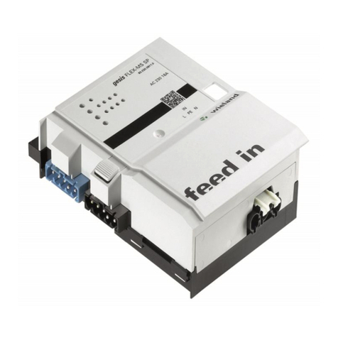
Wieland gesis FLEX-MS User manual

Wieland

Wieland gesis FLEX-MS User manual

Wieland gesis FLEX-8/0 (12) User manual

Wieland

Wieland gesis FLEX-8/0 (12) User manual

Wieland gesis RM Series User manual

Wieland

Wieland gesis RM Series User manual

Wieland GESIS FLEX-0/4 User manual

Wieland

Wieland GESIS FLEX-0/4 User manual

Wieland ricos FLEX User manual

Wieland

Wieland ricos FLEX User manual

Popular Control Unit manuals by other brands
Puls dimension PISA11 Series datasheet
Puls dimension

Puls dimension PISA11 Series datasheet

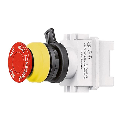
Eaton GHG 418 Series operating instructions

Eaton

Eaton GHG 418 Series operating instructions

HB-THERM HB-100 Safety Instructions and Quick Start Guide
HB-THERM

HB-THERM HB-100 Safety Instructions and Quick Start Guide

SMC Networks VM100-A Series Operation manual

SMC Networks

SMC Networks VM100-A Series Operation manual

INTERNATIONAL CARBONIC PF-2-PB installation manual
INTERNATIONAL CARBONIC

INTERNATIONAL CARBONIC PF-2-PB installation manual

GEM 537 instructions

GEM

GEM 537 instructions

DGH D3000M Series user manual

DGH

DGH D3000M Series user manual

Texas Instruments TMS320TCI648 Series user guide

Texas Instruments

Texas Instruments TMS320TCI648 Series user guide

Emerson TopWorx PD200 Installation, operation & maintenance manual

Emerson

Emerson TopWorx PD200 Installation, operation & maintenance manual

Zonar V4 Installation & user guide

Zonar

Zonar V4 Installation & user guide

blicube RLINK user manual

blicube

blicube RLINK user manual

Velocity VDOT-Mini IP instruction manual

Velocity

Velocity VDOT-Mini IP instruction manual

bmcm AMS-K quick start guide

bmcm

bmcm AMS-K quick start guide

DeDietrich VM Diematic Evolution Installation, user and service manual

DeDietrich

DeDietrich VM Diematic Evolution Installation, user and service manual

Bticino F3N400 installation manual

Bticino

Bticino F3N400 installation manual

ABB RDIO-01 user manual

ABB

ABB RDIO-01 user manual

Honeywell DirectLine DL424 user manual

Honeywell

Honeywell DirectLine DL424 user manual

Albion TMV3 Installation & operating manual

Albion

Albion TMV3 Installation & operating manual

manuals.online logo
manuals.online logoBrands
  • About & Mission
  • Contact us
  • Privacy Policy
  • Terms and Conditions

Copyright 2025 Manuals.Online. All Rights Reserved.