manuals.online logo
Brands
  1. Home
  2. •
  3. Brands
  4. •
  5. Wieland
  6. •
  7. Control Unit
  8. •
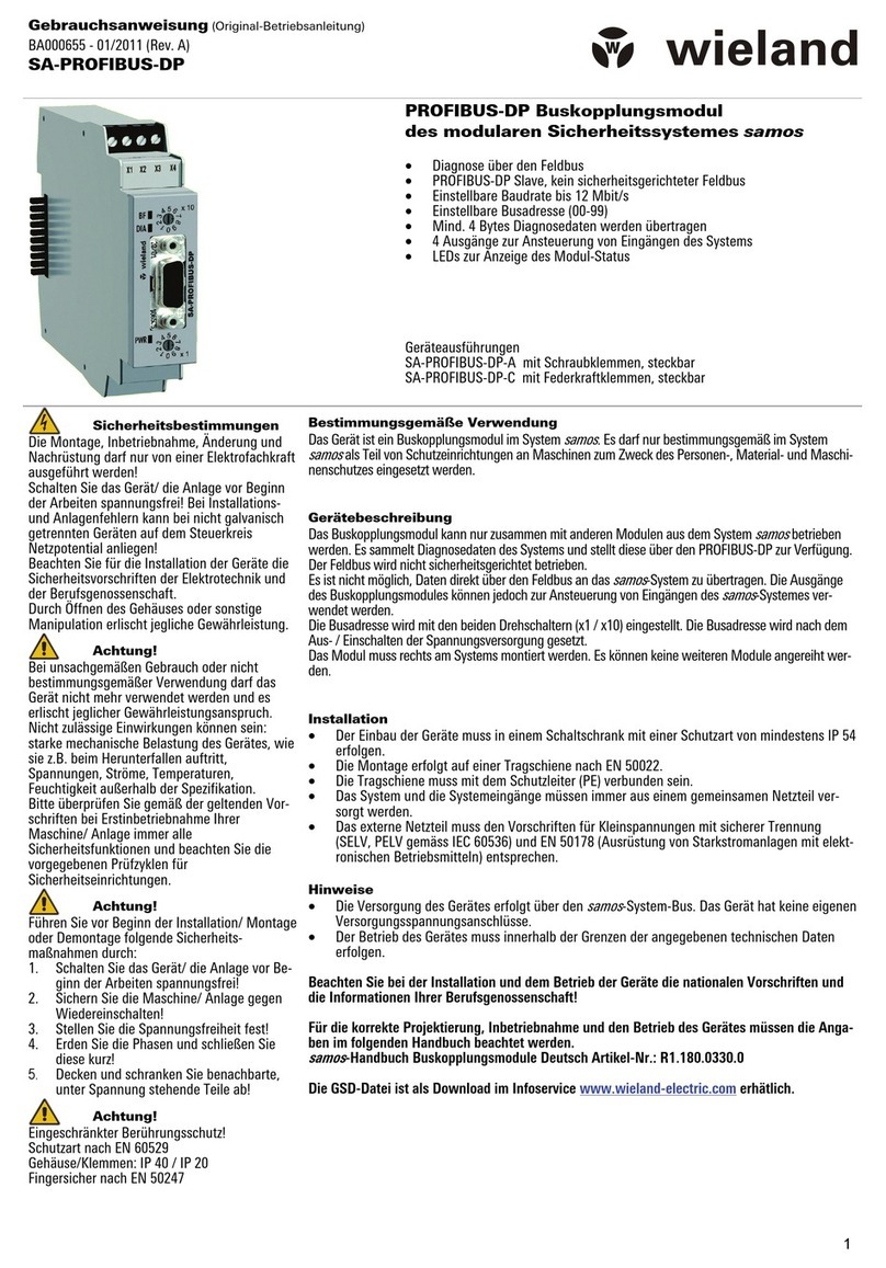
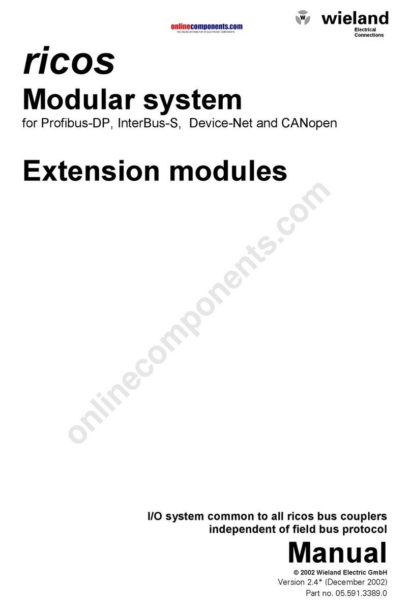
  9. Wieland GESIS FLEX-0/2W DC User manual

Wieland GESIS FLEX-0/2W DC User manual

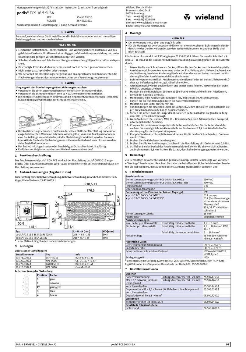
Montageanleitung (Original)
Installation Instructions (Translation based on Original Documentation)
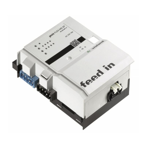
gesis FLEX-0/2W DC
2-fach Jalousieausgang (83.020.0627.0)
2-fold shutter output (83.020.0627.0)
Wieland Electric GmbH
Brennerstraße 10-14
96052 Bamberg
Tel.: +49 (951) 9324-0
Fax: +49 (951) 9324-198
Internet: www.wieland-electric.com
Email: info@wieland-electric.com
Doc. # BA000899 - 05/2014 (Rev. A)
gesis
FLEX-0/2W DC DE/EN 1
GEFAHR
•Nur Elektrofachkräfte dürfen dieses Gerät installieren und in Betrieb nehmen. Vor
Ausführung müssen sie diese Anleitung gelesen und verstanden haben.
•Gerät nicht öffnen. Keine Fremdobjekte einführen. Gerät von Wasser und Feuer fernhalten.
•Gerät nur in spannungsfreiem Zustand anschließen oder trennen.
•Die einschlägigen Normen, Richtlinien, Vorschriften und Bestimmungen des jeweiligen
Landes sind zu beachten.
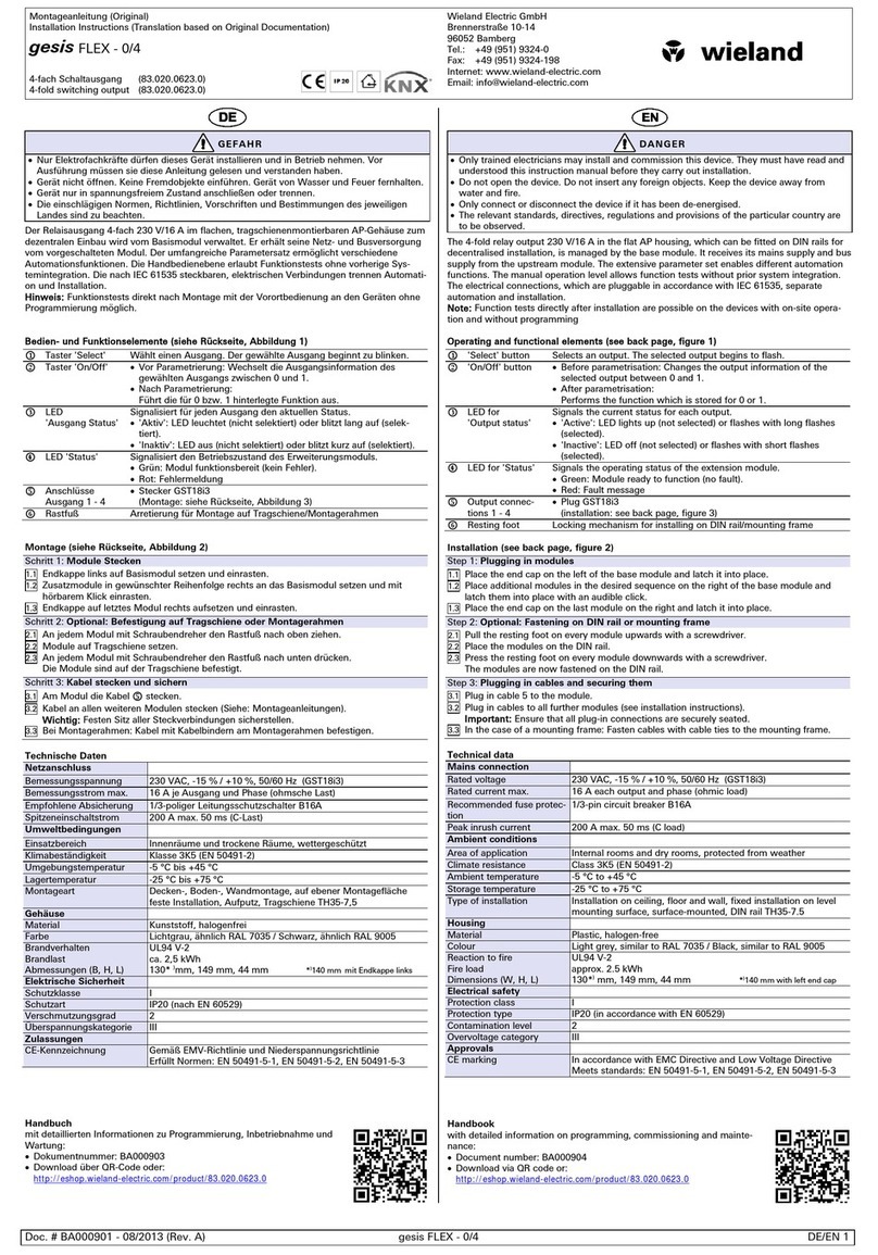
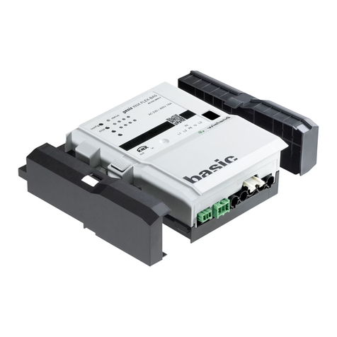
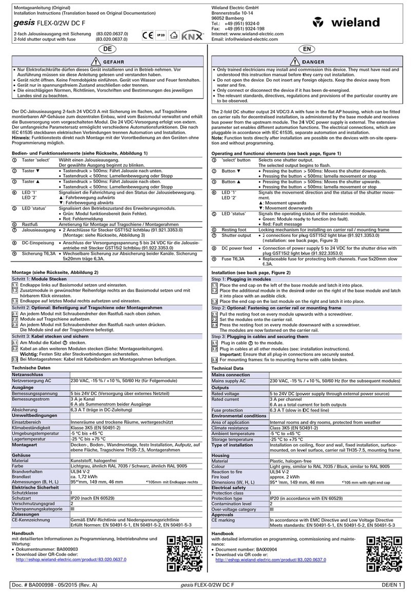
Der DC-Jalousieausgang 2-fach 24 VDC/3 A im flachen, auf Tragschiene montierbaren AP-
Gehäuse zum dezentralen Einbau, wird vom Basismodul verwaltet und erhält die Busversor-
gung vom vorgeschalteten Modul. Die 24 VDC-Versorgung erfolgt von extern. Der umfangrei-
che Parametersatz ermöglicht verschiedene Automationsfunktionen. Die nach IEC 61535
steckbaren elektrischen Verbindungen trennen Automation und Installation.
Hinweis:
Funktionstests direkt nach Montage mit der Vorortbedienung an den Geräten ohne
Programmierung möglich.
Bedien- und Funktionselemente (siehe Rückseite, Abbildung 1)

Taster 'select'
Wählt einen Jalousieausgang.
Der gewählte Ausgang beginnt zu blinken.

Taster ▼
•Tastendruck > 500ms: Fährt Jalousie nach unten.
•Tastendruck < 500ms: Lamellenbewegung oder Stopp

Taster ▲
•Tastendruck > 500ms: Fährt Jalousie nach oben.
•Tastendruck < 500ms: Lamellenbewegung oder Stopp

LED '1'
LED '2'
Signalisiert die Fahrrichtung und den Status der Jalousiebewegung.
▲: Fahrbewegung aufwärts
▼: Fahrbewegung abwärts

LED 'status' Signalisiert den Betriebszustand des Erweiterungsmoduls.
•Grün: Modul funktionsbereit (kein Fehler).
•Rot: Fehlermeldung

Rastfuß
Arretierung für Montage auf Tragschiene/Montagerahmen

Jalousieausgang
•2 Anschlüsse für Stecker GST15i2 lichtblau (91.921.3353.0)
(Montage: siehe Rückseite, Abbildung 3)

DC-Einspeisung
•Anschluss der Versorgungsspannung 5 bis 24 VDC für die Jalousie-
antriebe mit Stecker GST15i2 lichtblau (91.922.3353.0)
Montage (siehe Rückseite, Abbildung 2)
Schritt 1: Module Stecken
1.1 Endkappe links auf Basismodul setzen und einrasten.
1.2
Zusatzmodule in gewünschter Reihenfolge rechts an das Basismodul setzen und mit
hörbarem Klick einrasten.
1.3
Endkappe auf letztes Modul rechts aufsetzen und einrasten.
Schritt 2: Optional: Befestigung auf Tragschiene oder Montagerahmen
2.1 An jedem Modul mit Schraubendreher den Rastfuß nach oben ziehen.
2.2
Module auf Tragschiene aufsetzen.
2.3
An jedem Modul mit Schraubendreher den Rastfuß nach unten drücken.
Die Module sind auf der Tragschiene befestigt.
Schritt 3: Kabel stecken und sichern
3.1 Am Modul die Kabel  stecken.
3.2 Kabel an allen weiteren Modulen stecken (Siehe: Montageanleitungen).
Wichtig:
Festen Sitz aller Steckverbindungen sicherstellen.
3.3 Bei Montagerahmen: Kabel mit Kabelbindern am Montagerahmen befestigen.
Technische Daten
Netzanschluss
Netzversorgung AC
230 VAC, -15 % / +10 %, 50/60 Hz (für Folgemodule)
Ausgänge
Bemessungsspannung
5 bis 24V DC (Versorgung über externes Netzteil)
Bemessungsstrom
3 A je Kanal
6 A als Summenstrom beider Ausgänge
Empfohlene Absicherung
6,3 A T (träge in DC-Zuleitung)
Umweltbedingungen
Einsatzbereich
Innenräume und trockene Räume, wettergeschützt
Klimabeständigkeit
Klasse 3K5 (EN 50491-2)
Umgebungstemperatur
-5 °C bis +45 °C
Lagertemperatur
-25 °C bis +75 °C
Montageart
Decken-, Boden-, Wandmontage, feste Installation, Aufputz, auf
ebene Fläche, Tragschiene TH35-7,5, Montagerahmen
Gehäuse
Material
Kunststoff, halogenfrei
Farbe
Lichtgrau, ähnlich RAL 7035 / Schwarz, ähnlich RAL 9005
Brandverhalten
Brandlast
Abmessungen (B, H, L)
UL94 V-2
ca. 2 kWh
95*
)
mm, 149 mm, 44 mm *
)
105mm
mit Endkappe rechts
Elektrische Sicherheit
Schutzklasse
I
Schutzart
IP20 (nach EN 60529)
Verschmutzungsgrad
2
Überspannungskategorie
III
Zulassungen
CE-Kennzeichnung
Gemäß EMV-Richtlinie und Niederspannungsrichtlinie
Erfüllt Normen: EN 50491-5-1, EN 50491-5-2, EN 50491-5-3
Handbuch
mit detaillierten Informationen zu Programmierung, Inbetriebnahme und
Wartung:
•Dokumentnummer: BA000903
•Download über QR-Code oder:
http://eshop.wieland-electric.com/product/83.020.0627.0
DANGER
•Only trained electricians may install and commission this device. They must have read and
understood this instruction manual before they carry out installation.
•Do not open the device. Do not insert any foreign objects. Keep the device away from
water and fire.
•Only connect or disconnect the device if it has been de-energised.
•The relevant standards, directives, regulations and provisions of the particular country are
to be observed.
The 2-fold DC shutter output 24 VDC/3 A in the flat AP housing, which can be fitted on carrier
rails for decentralised installation, is administered by the base module and receives bus power
from the upstream module. The 24 VDC power supply is external. The extensive parameter set
enables different automation functions. The electrical connections, which are pluggable in
accordance with IEC 61535, separate automation and installation.
Note:
Function tests directly after installation are possible on the devices with on-site opera-
tion and without programming.
Operating and functional elements (see back page, figure 1)

'select' button
Selects one shutter output.
The selected output begins to flash.

Button ▼
•Pressing the button > 500ms: Moves the shutter downwards.
•Pressing the button < 500ms: lamella movement or stop

Button ▲
•Pressing the button > 500ms: Moves the shutter upwards.
•Pressing the button < 500ms: lamella movement or stop

LED '1'
LED '2'
Signals the movement direction and the status of the shutter move-
ment.
▲: Movement upwards
▼: Movement downwards

LED 'status'
Signals the operating status of the extension module.
•Green: Module ready to function (no fault).
•Red: Fault message

Resting foot
Locking mechanism for installing on carrier rail/mounting frame

Shutter output
•
2 connections for plug GST15i2 light blue (91.921.3353.0)
(Installation: see back page, Figure 3)

DC power feed
•Connection of power supply 5 to 24 VDC for the shutter drive with
plug GST15i2 light blue (91.922.3353.0)
Installation (see back page, Figure 2)
Step 1: Plugging in modules
1.1 Place the end cap on the left of the base module and latch it into place.
1.2
Place the additional module in the desired order on the right of the base module and latch
it into place with an audible click.
1.3
Place the end cap on the last module on the right and latch it into place.
Step 2: Optional: Fastening on carrier rail or mounting frame
2.1 Pull the resting foot on every module upwards with a screwdriver.
2.2
Set the modules onto the carrier rail.
2.3
Press the resting foot on every module downward with a screwdriver.
The modules are now fastened on the carrier rail.
Step 3: Plugging in cables and securing them
3.1 Plug in cable  to the module.
3.2 Plug in cables at all other modules (see: installation instructions).
Important:
Ensure that all plug-in connections are securely seated.
3.3 For mounting frames: fix to mounting frame with cable binders.
Technical Data
Mains connection
Mains supply AC
230 VAC, -15 % / +10 %, 50/60 Hz (for the subsequent modules)
Outputs
Rated voltage
5 to 24V DC (power supply through external power source)
Rated current
3 A per channel
6 A as a total current for both outputs
Recommended fuse protec-
tion
6.3 A T (slow in DC feed line)
Environmental conditions
Area of application
Internal rooms and dry rooms, protected from weather
Climate resistance
Class 3K5 (EN 50491-2)
Ambient temperature
-5 °C to +45 °C
Storage temperature
-25 °C to +75 °C
Type of installation
Installation on ceiling, floor and wall, fixed installation, surface-
mounted, on level surface, carrier rail TH35-7.5, mounting frame
Housing
Material
Plastic, halogen-free
Colour
Light grey, similar to RAL 7035 / Black, similar to RAL 9005
Reaction to fire
Fire load
Dimensions (W, H, L)
UL94 V-2
approx. 2 kWh
95*
)
mm, 149 mm, 44 mm *
)
105 mm with right end cap
Electrical safety
Protection class
I
Protection type
IP20 (in accordance with EN 60529)
Contamination level
2
Over-voltage category
III
Approvals
CE marking
In accordance with EMC Directive and Low Voltage Directive
Meets standards: EN 50491-5-1, EN 50491-5-2, EN 50491-5-3
Handbook
with detailed information on programming, commissioning and mainte-
nance:
•Document number: BA000904
•Download via QR code or:
http://eshop.wieland-electric.com/product/83.020.0627.0
Montageanleitung (Original)
Installation Instructions (Translation based on Original Documentation)
gesis FLEX-0/2W DC
2-fach Jalousieausgang (83.020.0627.0)
2-fold shutter output (83.020.0627.0)
Wieland Electric GmbH
Brennerstraße 10-14
96052 Bamberg
Tel.: +49 (951) 9324-0
Fax: +49 (951) 9324-198
Internet: www.wieland-electric.com
Email: info@wieland-electric.com
Doc. # BA000899 - 05/2014 (Rev. A)
gesis
FLEX-0/2W DC DE/EN 2
Abbildung 1: Bedien- und Funktionselemente
Figure 1: Operating and functional elements
Abbildung 2: Montage
Figure 2: Installation
Abbildung 3: Montage der Stecker
Figure 3: Installation of the plugs
GST15i2
(91.922.3353.0 und/and 91.921.3353.0)
Drehmoment
0,5 … 0,7 Nm
4,4 … 6,2 lb-in
Torque
Instructions de montage (Traduction de la notice originale)
Istruzioni per il montaggio (Traduzione delle istruzioni originali)
gesis FLEX-0/2W DC
Sortie de store 2 postes (83.020.0627.0)
Uscita veneziana a 2 canali (83.020.0627.0)
Wieland Electric GmbH
Brennerstraße 10-14
96052 Bamberg
Tel.: +49 (951) 9324-0
Fax: +49 (951) 9324-198
Internet: www.wieland-electric.com
Email: info@wieland-electric.com
Doc. # BA000899 - 05/2014 (Rev. A)
gesis
FLEX-0/2W DC FR/IT 1
DANGER
•Seuls les électriciens spécialisés sont autorisés à installer cet appareil et à le mettre en
service. Avant de commencer, ils doivent avoir lu et compris ces instructions.
•Ne pas ouvrir l'appareil. Ne pas insérer d'objets tiers. Tenir l'appareil éloigné de l'eau et du
feu.
•Ne raccorder l'appareil ou ne le déconnecter que lorsqu'il n'est pas sous tension.
•Respecter les normes, directives, prescriptions et dispositions applicables dans chaque
pays.
La sortie de store 2 postes CC de 24 VCC/3 A en boîtier plat, monté sur le rail pour le montage
décentralisé est géré par le module de base et utilise l'alimentation du bus du module pré-
cédent. L'alimentation 24 VCC est externe. Le bloc de paramètres complet permet différentes
fonctions d'automatisation. Les raccords électriques enfichables selon CEI 61535 séparent
l'automatisation et l'installation.
Remarque :
les tests de fonctionnement sont possibles directement après le montage avec la
commande sur site des appareils.
Éléments de commande et de fonction (voir verso, figure 1)

Bouton 'select' Sélectionne la sortie de store.
La sortie sélectionnée commence à clignoter.

Bouton ▼
•Appui sur le bouton > 500 ms : le store descend.
•
Appui sur le bouton < 500 ms : les lamelles bougent ou Arrêt

Bouton ▲
•Appui sur le bouton > 500 ms : le store monte.
•
Appui sur le bouton < 500 ms : les lamelles bougent ou Arrêt

LED '1'
LED '2'
Signale le sens de déplacement et l'état du mouvement de store.
▲: déplacement vers le haut
▼: déplacement vers le bas

LED
'status'
Signale l'état de fonctionnement du module d'extension.
•Vert : module prêt à fonctionner (pas d'erreur).
•Rouge : message d'erreur

Pied encliquetab-
le
Arrêt pour le montage sur rail porteur/cadre de montage

Sortie de store
•2 raccordements pour le connecteur GST15i2 bleu clair
(91.921.3353.0)
(Montage : voir verso, figure 3)

Alimentation CC
•Raccordement de la tension d'alimentation de 5 à 24 VCC pour le
fonctionnement du store avec le connecteur GST15i2 bleu clair
(91.922.3353.0)
Montage (voir verso, figure 2)
Étape 1 : Enfichage du module
1.1 Monter le capuchon d'extrémité sur le côté gauche du module de base et l'encliqueter.
1.2
Monter les modules supplémentaires dans l'ordre souhaité à droite du module de base et
les encliqueter jusqu'à entendre un clic.
1.3
Monter le capuchon d'extrémité sur le côté droit du dernier module et l'encliqueter.
Étape 2 : En option : fixation sur un rail porteur ou un cadre de montage
2.1 Tirer le pied encliquetable vers le haut sur chaque module à l'aide d'un tournevis.
2.2 Placer les modules sur le rail porteur.
2.3
Pousser le pied encliquetable vers le bas à l'aide d'un tournevis sur chaque module.
Les modules sont fixés sur le rail porteur.
Étape 3 : Enfichage du câble et fixation
3.1 Raccorder les câbles  sur le module.
3.2 Raccorder le câble à tous les autres modules (voir : instructions de montage).
Important :
s'assurer de la bonne fixation de tous les raccords enfichés.
3.3 Avec cadre de montage : fixer les câbles sur le cadre de montage à l'aide de serre-câbles.
Caractéristiques techniques
Raccordement secteur
Tension secteur CA
230 VCA, -15 % / +10 %, 50/60 Hz (pour les modules suivants)
Sorties
Tension nominale
5 à 24 VCC (alimentation via un bloc d'alimentation externe)
Intensité nominale
3 A par canal
6 A en tant somme de l'intensité des deux sorties
Fusible recommandé
6,3 A T (à retardement pour l'alimentation CC)
Conditions ambiantes
Zones d'utilisation
Espaces intérieurs et locaux secs, protégés contre les intempéri-
es
Résistance à l'environne-
ment
Classe 3K5 (EN 50491-2)
Température ambiante
de -5 °C à +45 °C
Température de stockage
de -25 °C à +75 °C
Type de montage
Montage au plafond, au sol et au mur ; installation fixe, en
saillie, sur une surface plane, rail porteur TH35-7,5, cadre de
montage
Boîtier
Matériau
Matière plastique, sans halogène
Couleur
gris clair, similaire à RAL 7035 / noir, similaire à RAL 9005
Comportement au feu
Charge d'incendie
Dimensions (l, H, L)
UL94 V-2
env. 2 kWh
95*)mm, 149 mm, 44 mm *)105 mm avec capuchon
d'extrémité à droite
Sécurité électrique
Classe de protection
I
Indice de protection
IP20 (selon EN 60529)
Degré d'encrassement
2
Catégorie de surtension
III
Homologations
Marquage CE
Conformément à la directive CEM et Basse tension
Conforme aux normes : EN 50491-5-1, EN 50491-5-2, EN
50491-5-3
Notice
comprenant des informations détaillées sur la programmation, mise en
service et maintenance :
•Numéro de document : BA000904
•Téléchargement via code QR ou :
http://eshop.wieland-electric.com/product/83.020.0627.0
PERICOLO
•L'installazione e la messa in servizio di questo apparecchio devono essere eseguiti
esclusivamente da elettrotecnici. che devono aver letto e compreso le presenti istruzioni
prima di effettuare qualsiasi operazione.
•Non aprire l'apparecchio. Non introdurre oggetti estranei.
Mantenere l'apparecchio lontano
da acqua e fuoco.
•Collegare o scollegare l'apparecchio solo in assenza di tensione.
•
Rispettare le norme, direttive, prescrizioni e disposizioni in vigore nel paese di impiego.
L'uscita veneziana DC a 2 canali 24 VDC/3 A in custodia da parete piatta su guida di supporto
per installazione decentrata è gestita dal modulo base e riceve l'alimentazione bus dal modulo
installato a monte. L'alimentazione 24 VDC proviene dall'esterno. L'ampia gamma di parametri
impostabili consente di realizzare diverse funzioni di automazione. I collegamenti elettrici a
innesto a norma IEC 61535 separano automazione e installazione.
Nota:
è possibile eseguire la verifica delle funzioni subito dopo l'installazione con il comando
locale presente sugli apparecchi senza programmazione.
Elementi di comando e funzionali (vedere a tergo la figura 1)

Tasto 'select' Consente di selezionare un'uscita veneziana.
L'uscita selezionata inizia a lampeggiare.

Tasto ▼
•Premendo il tasto per > 500ms, si abbassano le veneziane.
•
Pressione del tasto < 500ms: movimentazione lamelle o arresto

Tasto ▲
•Premendo il tasto per > 500ms, si alzano le veneziane.
•
Pressione del tasto < 500ms: movimentazione lamelle o arresto

LED '1'
LED '2'
Segnala la direzione e lo stato del movimento della veneziana.
▲: Movimento verso l'alto
▼: Movimento verso il basso

LED
'status'
Segnala le condizioni di esercizio del modulo di espansione.
•Verde: modulo pronto per l'uso (nessun errore).
•Rosso: segnalazione di errore

Piedino di
fissaggio
Dispositivo di fissaggio per l'installazione su guida di supporto/telaio di
montaggio

Uscita veneziana
•2 collegamenti per connettore GST15i2 azzurro (91.921.3353.0)
(montaggio: vedere a tergo, figura 3)

Alimentazione
DC
•Collegamento della tensione di alimentazione da 5 a 24 VDC per
l'azionamento veneziana con connettore GST15i2 azzurro
(91.922.3353.0)
Montaggio (vedere a tergo, figura 2)
Passo 1: inserimento dei moduli
1.1 Inserire il cappuccio terminale a sinistra sul modulo base.
1.2 Inserire gli altri moduli nella sequenza desiderata a destra del modulo base, fino ad
avvertire il "clic" che indica l'avvenuto bloccaggio.
1.3
Applicare il cappuccio terminale sull'ultimo modulo a destra.
Passo 2: opzionale: fissaggio su guida di supporto o telaio di montaggio
2.1 Su ogni modulo spostare il piedino di fissaggio verso l'alto con un cacciavite.
2.2
Posizionare i moduli sulla guida di supporto.
2.3 Su ogni modulo premere il piedino di fissaggio verso il basso con un cacciavite.
I moduli sono ora fissati alla guida di supporto.
Punto 3: inserimento e fissaggio dei cavi
3.1 Inserire il cavo  sul modulo.
3.2 Inserire i cavi in tutti gli altri moduli (vedere le istruzioni di montaggio).
Importante:
assicurarsi che tutti i connettori siano saldamente fissati.
3.3 In caso di montaggio su telaio: fissare i cavi al telaio con fascette fermacavi.
Dati tecnici
Collegamento di rete
Alimentazione di rete AC
230 VAC, -15 % / +10 %, 50/60 Hz (per moduli successivi)
Uscite
Tensione nominale
da 5 d 24V DC (alimentazione tramite alimentatore esterno)
Corrente nominale
3 A per canale
6 A come corrente totale delle due uscite
Protezione consigliata
6,3 A T (con fusibile ritardato nella linea di alimentazione DC)
Condizioni ambientali
Campo d'impiego
In ambienti interni, asciutti e protetti dagli agenti atmosferici
Resistenza ai fattori climati-
ci
Classe 3K5 (EN 50491-2)
Temperatura ambiente
-5 °C ... +45 °C
Temperatura di stoccaggio
-25 °C ... +75 °C
Tipo di montaggio
A soffitto, pavimento, parete, installazione fissa, a vista, su
superficie piana, guida di supporto TH35-7,5, telaio di montag-
gio
Custodia
Materiale
PVC, senza alogenati
Colore
Grigio chiaro, simile a RAL 7035 / Nero, simile a RAL 9005
Resistenza al fuoco
Carico comburente
Dimensioni (LxHxL)
UL94 V-2
ca. 2 kWh
95*)mm, 149 mm, 44 mm *)105mm con cappuccio
terminale a destra
Sicurezza elettrica
Classe di protezione
i
Grado di protezione
IP20 (secondo EN 60529)
Grado d'inquinamento
2
Categoria di sovratensione
III
Omologazioni
Marchio CE
Secondo la Direttiva EMC e la Direttiva bassa tensione
Conforme alle norme: EN 50491-5-1, EN 50491-5-2, EN 50491-
5-3
Manuale
con informazioni dettagliate sulla programmazione, messa in servizio e
manutenzione:
•Documento numero: BA000904
•Download mediante codice QR o:
http://eshop.wieland-electric.com/product/83.020.0627.0
Instructions de montage (Traduction de la notice originale)
Istruzioni per il montaggio (Traduzione delle istruzioni originali)
gesis FLEX-0/2W DC
Sortie de store 2 postes (83.020.0627.0)
Uscita veneziana a 2 canali (83.020.0627.0)
Wieland Electric GmbH
Brennerstraße 10-14
96052 Bamberg
Tel.: +49 (951) 9324-0
Fax: +49 (951) 9324-198
Internet: www.wieland-electric.com
Email: info@wieland-electric.com
Doc. # BA000899 - 05/2014 (Rev. A)
gesis
FLEX-0/2W DC FR/IT 2
Figure 1: Éléments de commande et de fonction
Figura 1: Elementi di comando e funzionali
Figure 2: Montage
Figura 2: Montaggio
Figure 3: Montage des connecteurs
Figura 3: Montaggio dei connettori
GST15i2
(91.922.3353.0 et/e 91.921.3353.0)
Couple
0,5 … 0,7 Nm
4,4 … 6,2 lb-in
Coppia di
serraggio

This manual suits for next models

1

Other Wieland Control Unit manuals

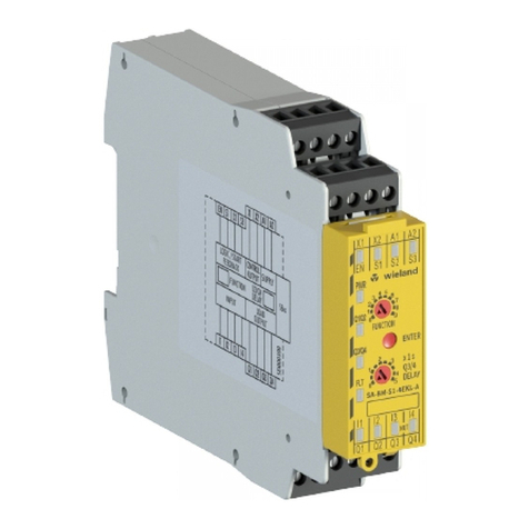
Wieland SA-BM-S1-4EKL-A User manual

Wieland

Wieland SA-BM-S1-4EKL-A User manual

Wieland gesis FLEX-0/2W DC F User manual

Wieland

Wieland gesis FLEX-0/2W DC F User manual

Wieland SP-COP1 User manual

Wieland

Wieland SP-COP1 User manual

Wieland gesis FLEX-8/0 (12) User manual

Wieland

Wieland gesis FLEX-8/0 (12) User manual

Wieland ricos FLEX User manual

Wieland

Wieland ricos FLEX User manual

Wieland ricos User manual

Wieland

Wieland ricos User manual

Wieland podis FCS 6 5 SI SA User manual

Wieland

Wieland podis FCS 6 5 SI SA User manual

Wieland GESIS FLEX-0/4 User manual

Wieland

Wieland GESIS FLEX-0/4 User manual

Wieland podis FCS 16 5 SI SA User manual

Wieland

Wieland podis FCS 16 5 SI SA User manual

Wieland gesis KNX FLEX-BAS User manual

Wieland

Wieland gesis KNX FLEX-BAS User manual

Wieland PROFIBUS-DP Series User manual

Wieland

Wieland PROFIBUS-DP Series User manual

Wieland gesis RM Series User manual

Wieland

Wieland gesis RM Series User manual

Wieland gesis FLEX-MS User manual

Wieland

Wieland gesis FLEX-MS User manual

Popular Control Unit manuals by other brands

Nautel NxLink Technical instruction manual

Nautel

Nautel NxLink Technical instruction manual

ProSoft Technology ILX34-MBS485 user manual

ProSoft Technology

ProSoft Technology ILX34-MBS485 user manual

Telit Wireless Solutions HE920 Series Product description

Telit Wireless Solutions

Telit Wireless Solutions HE920 Series Product description

Digi ConnectCore 6 Plus Hardware reference manual

Digi

Digi ConnectCore 6 Plus Hardware reference manual

Watts 909 Series Installation, maintenance & repair

Watts

Watts 909 Series Installation, maintenance & repair

ICP CON I-7560U user manual

ICP CON

ICP CON I-7560U user manual

schmersal PSCBR-C-100 Series installation manual

schmersal

schmersal PSCBR-C-100 Series installation manual

CommScope ION-M7HP EU manual

CommScope

CommScope ION-M7HP EU manual

Panduit TX6A 10Gig installation instructions

Panduit

Panduit TX6A 10Gig installation instructions

Advantech USB-4716 user manual

Advantech

Advantech USB-4716 user manual

Moog G761 Series Installation and operation instruction

Moog

Moog G761 Series Installation and operation instruction

RICOMAN Gemini installation instructions

RICOMAN

RICOMAN Gemini installation instructions

Harvia CG170T manual

Harvia

Harvia CG170T manual

Graco ProMix Auto Installation

Graco

Graco ProMix Auto Installation

Digi Connect Wi-Wave Hardware reference

Digi

Digi Connect Wi-Wave Hardware reference

ASAHI YUKIZAI Dymatrix AVSDV user manual

ASAHI YUKIZAI

ASAHI YUKIZAI Dymatrix AVSDV user manual

SICK CDB620 operating instructions

SICK

SICK CDB620 operating instructions

Bray TRI LOK Installation, operation & maintenance manual

Bray

Bray TRI LOK Installation, operation & maintenance manual

manuals.online logo
manuals.online logoBrands
  • About & Mission
  • Contact us
  • Privacy Policy
  • Terms and Conditions

Copyright 2025 Manuals.Online. All Rights Reserved.