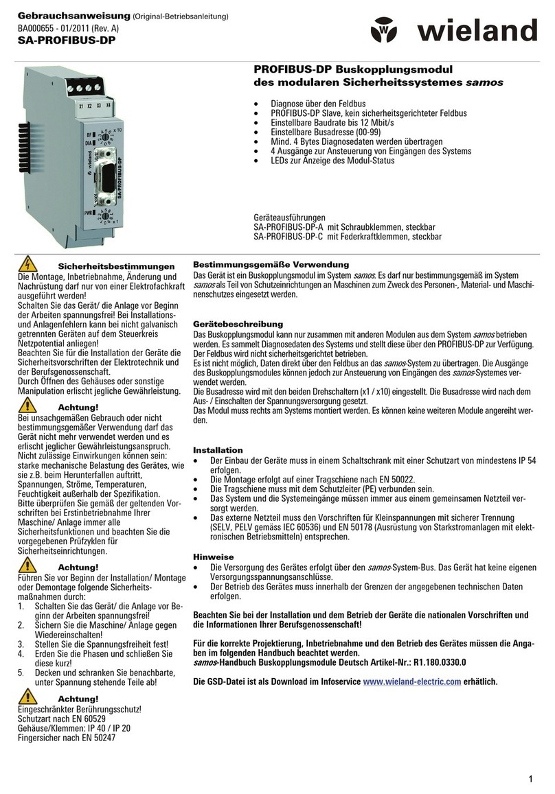
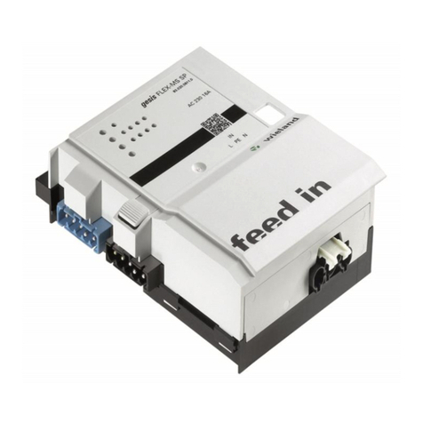
Wieland podis FCS 16 5 SI SA User manual

Montageanleitung (Original) / Installation instruction (translation from original)
podis® FCS 16 5 SI SA
M32 75.456.0353.1
RST25i5 75.453.0353.1
Anschlussmodul mit Doppelabgang, 5-polig, Schraubklemme
Wieland Electric GmbH
Brennerstraße 10–14
96052 Bamberg
Tel.: +49 (951) 9324-0
Fax: +49 (951) 9324-198
Internet: www.wieland-electric.com
Email: info@wieland-electric.com
Dok. # BA001321 – 03/2023 (Rev. A) podis® FCS 16 5 SI SA DE
HINWEIS
Personal, welches dieses Gerät installiert und in Betrieb nimmt oder wartet, muss diese
Anleitung gelesen und verstanden haben.
WARNUNG
•Elektrische Installationen, Inbetriebnahme- und Wartungsarbeiten dürfen nur von aus-
gebildeten Elektrofachkräften mit einschlägiger Unfallverhütungs-Ausbildung und unter
Beachtung der gültigen Vorschriften durchgeführt werden.
•Schutzmaßnahmen und Schutzeinrichtungen müssen den gültigen Vorschriften entspre-
chen.
•Beschädigte Produkte dürfen weder installiert noch in Betrieb genommen werden.
•Nicht unter Last anschließen oder trennen!
•Vor der Arbeit am Flachleitungsenergiebus und an angeschlossenen Komponenten die
Flachleitung und Anschlusskomponenten sicher vom Versorgungsnetz trennen.
HINWEIS
Umgang mit den Durchdringungs-Kontaktierungsschrauben:
•Verwenden Sie einen pneumatischen oder elektrischen Schraubendreher.
•Verwenden Sie Schrauberklingen Torx 15 × 50, siehe Bestellinformationen.
•Die Kontaktierungsschrauben sind vollständig eingedreht, wenn die weißen Tiefenmaß-
hülsen bündig zur Oberfläche der Schraubenschächte sind.
•Die Kontaktierungsschrauben dürfen an derselben Stelle der Flachleitung nur einmal
eingedreht werden. Wird eine Schraube wieder gelöst, kann das Anschlussmodul um
eine Bauteillänge versetzt wieder mit der Flachleitung kontaktiert werden. Die zuvor
kontaktierte Stelle der Flachleitung muss mit einem Isolierband verschlossen werden,
siehe Bestellinformationen.
•Der Betrieb mit abgerissenen oder beschädigten Schrauben ist nicht zulässig.
•Es dürfen nur Originalschrauben von Wieland verwendet werden!
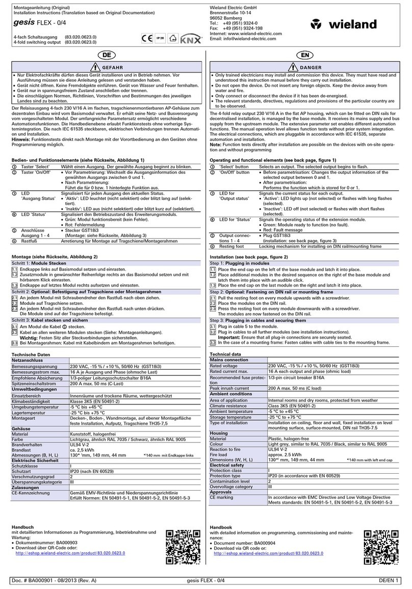
Funktionsbeschreibung
Das Anschlussmodul podis®CON FCS wird auf der Flachleitung podis®CON 5G16 ange-
bracht. Über das Anschlussmodul wird Haupt- und Hilfsenergie unterbrechungsfrei aus der
Flachleitung entnommen.
Einbau-Abmessungen (Angaben in mm)
Lieferumfang ohne Kabelverschraubung, Kabelverschraubung aus Zubehör mitbestellen.
Abgebildete Variante: 75.453.0353.1
Typ
L × B × H [mm]
HO [mm]
podis® FCS 16 5 SI SA 2xRST25i5
248* × 85 × 145
50,8
podis® FCS 16 5 SI SA 2xM32
218 × 85 × 145
50,8
* L= ca. Maß mit eingebauten Kabelverschraubungen
Leitungen
Zugelassene Flachleitungen:
Bestellnummer
Typ
Info
00.771.0307.1
LSHF 5G16
B2ca-s1a-d1-a1
00.729.0307.1
XPE 5G16
CE, UL 1277 TC-ER
00.770.0307.1
Li2HH 5G16
B2ca-s1a-d1-a1
00.710.0307.1
XPE 5G16
Cca-s1-d2-a1
Leiterzuordnung der Flachleitung
Position
Farbe
1
grau
2
schwarz
PE
grün/gelb
3
blau
4
braun
Montage
HINWEIS
•Der Untergrund muss eben und tragfähig sein.
•Für die Montage auf dem Untergrund dürfen nur die vorgesehenen Bohrungen in der Bo-
denplatte des Gerätes verwendet werden. Weitere Bohrungen an anderer Stelle sind
nicht zulässig!
Für das Anschlussmodul mit RST-Abgängen 75.453.0353.1 führen Sie nur die Schritte 1 – 4
und 15 −16 aus. Für die Module mit Kabelverschraubung als Abgang führen Sie alle Schritte
durch.
1. Lösen Sie die vier Schrauben am Deckel, öffnen Sie den Deckel und die Anschlussplatte.
2. Anschlussmodul von unten kommend unter der Flachleitung einschieben. Saubere Lage
der Kodierung beachten: Kodierung/Stufe auf einer der kurzen Seiten muss mit der Ko-
dierung/Stufe im Anschlussmodul übereinstimmen.
3. Bohrmittelpunkte anreißen, Anschlussmodul entfernen oder zur Seite schieben und Lö-
cher zur Befestigung bohren, ggf. Dübel einstecken.
4. Anschlussmodul wieder positionieren und an der Wand fixieren. Verwenden Sie, wenn
möglich, Unterlegscheiben.
5. Manteln Sie die Rundleitung 250 mm ab (Bei Punkt 8 wird auf die finalen Aderlängen,
gemäß der Tabelle 1 gekürzt).
6. Montieren Sie die Kabelverschraubungen M32 mit 5,0 Nm im Anschlussmodul.
7. Führen Sie die Rundleitungen durch die Kabelverschraubung.
8. Manteln Sie alle Leiter auf 190 mm ab.
9. Vor dem Biegen die einzelnen Leiter auf Länge ca. 25 mm abisolieren und nach dem Bie-
gen auf 20 mm abisolierte Länge zurückschneiden.
10. Stellen Sie sicher, dass die Länge der abisolierten Leiter nach dem Biegen der Leitung
über alle Litzen 20 mm beträgt.
11. Wenn Sie Leiter 1,5 – 4 mm² / AWG 16 – 12 anschließen, sind Aderendhülsen zwingend
erforderlich (siehe Zubehör).
12. Crimpen Sie zwei zusammengehörende Leiter und schließen Sie die Leiter direkt da-
nach an die jeweilige Schraubklemmstelle an. Drehmoment 1,2 Nm. Wiederholen Sie
den Vorgang für die übrigen Leiterpaare.
13. Klappen Sie die Anschlussplatte zu und ziehen Sie die beiden Schrauben fest. Drehmo-
ment: 1,2 Nm.
14. Drehen Sie die Kabelverschraubung fest.
15. Drehen Sie alle Kontaktierungsschrauben in die Flachleitung ein. Drehmoment: 2,0 Nm.
16. Schließen Sie den Deckel des Anschlussmoduls und ziehen Sie alle vier Schrauben fest
an. Drehmoment: 1,2 Nm. Achten Sie darauf, dass keine Leitungen gequetscht werden.
Demontage
Zur Demontage des Anschlussmoduls gehen Sie in umgekehrter Reihenfolge vor, wie unter
4 "Montage" beschrieben. Beachten Sie dabei die betreffenden Sicherheitshinweise. Beach-
ten Sie insbesondere, dass Arbeiten unter Spannung grundsätzlich verboten sind.
Technische Daten
Anschlussdaten
Bemessungsspannung podis® FCS 16 5 SI SA 2xM32
690 V AC
Bemessungsspannung podis® FCS 16 5 SI SA 2xRST25i5
400 V AC
Prüfspannung
6 kV
Überspannungskategorie
3
Bemessungsstrom (Summe der beiden Abgänge)
IEC
•podis® FCS 16 5 SI SA 2xM32
•podis® FCS 16 5 SI SA 2xRST25i5
63 A
(max. 40 °C)
63 A (Der Bemessungs-
strom eines einzelnen
Abgangs darf
25 A/32 A1) nicht über-
schreiten.)
Bemessungsquerschnitt
16 mm²
Anschlussart
Schraubklemmen
Anschlussvermögen
Zwei Leiter pro Klemmstelle
feindrähtig mit Aderendhülse
1,5 … 6 mm²
Ein Leiter pro Klemmstelle
feindrähtig mit Aderendhülse
1,5 … 16,0 mm², AWG
16 – 6
feindrähtig ohne Adernendhülsen
6 … 16,0 mm²
Abisolierlänge
25 mm (bei Aderend-
hülse 2 × 6 mm²)
Allgemeine Daten
Betriebsumgebungstemperatur
-25 °C … +55 °C
Lagertemperatur
-40 °C … +70 °C
Schutzart in verschraubtem Zustand
IP65 nach EN 60529
NEMA Type 1
Schlagfestigkeit
IK09
1) Beachten Sie die Derating-Kurve des RST 25i5-Systems. Diese finden Sie im RST®-Kata-
log 0690.x oder im eShop unter Downloads der Bestell-Nr. 99.576.0000.7.
Bestellinformationen
Zubehör
Kabelverschraubung
M32 × 1,5 schwarz, für Rund-
leitungen mit
Leitungsdurchmesser 10 – 21 mm
Z5.507.1753.1
Leitungsdurchmesser 18 – 25 mm
Z5.507.1653.1
Verschlussstopfen
05.506.7453.1
Gegenmutter M32 × 1,5 schwarz (für Kabelverschraubungen und
Verschlussstopfen)
05.505.0353.1
Doppeladerendhülse 2 × 6 mm²
06.600.7200.0
Werkzeuge
Schraubendreher-Bit Torx 15x70
06.502.6410.0
Ersatzteile / Reparaturteile
Isolierband
Z6.563.7800.0

Montageanleitung (Original) / Installation instruction (translation from original)
podis® FCS 16 5 SI SA
M32 75.456.0353.1
RST25i5 75.453.0353.1
Connection module 5-pole, screw terminals
Wieland Electric GmbH
Brennerstraße 10–14
96052 Bamberg
Tel.: +49 (951) 9324-0
Fax: +49 (951) 9324-198
Internet: www.wieland-electric.com
Email: info@wieland-electric.com
Doc. # BA001321 – 03/2023 (Rev. A) podis® FCS 16 5 SI SA EN
NOTICE
Personnel which installs and operates or maintains this device must have read and under-
stood these instructions.
WARNING
•Electric installations, placing devices into operation and maintenance tasks may only be
carried out by qualified electricians with relevant training in accident prevention and
while adhering to applicable regulations.
•Protective measures and mechanisms must correspond to applicable regulations.
•Damaged products must neither be installed nor put into operation.
•Connect or disconnect only when de-energized!
•Before performing work on the power bus or the connected components the cable and
components must be disconnected from the mains.
NOTICE
Handling the penetrating contact screws:
•Use a pneumatic or electric screwdriver.
•Use a Torx 15 × 50 screw blade, see ordering information.
•The contact screws are correctly tightened if the white depth gauge ferrules are level
with the surface of the housing.
•The piercing screws must be screwed in the same position only once. If a screw is loos-
ened, the connection module might be connected again by an offset of a component
length on the cable. The previously terminated position with the open sheath must be
protected by insulating sealing tape, see ordering information.
•Operating the module with damaged or broken screws is not permitted.
•Only original piercing screws from Wieland Electric must be used.
Functional description
The podis® CON FCS connection module is installed on the podis® CON 5G16 tray cable. With
the connection module, energy is taken from or fed into the tray cable without having to cut
or otherwise prepare the cable.
Installation dimensions (specifications in mm)
Cable screw gland not included in scope of delivery; order cable screw gland from Accesso-
ries.
Displayed model: 75.453.0353.1
Type
L × B × H [mm]
HO [mm]
podis® FCS 16 5 SI SA 2xRST25i5
248* × 85 × 145
50.8
podis® FCS 16 5 SI SA 2xM32
218 × 85 × 145
50.8
* L= approx. dimension with cable screw glands installed
Ducts
Approved flat cables:
Article number
Type
Info
00.771.0307.1
LSHF 5G16
B2ca-s1a-d1-a1
00.729.0307.1
XPE 5G16
CE, UL 1277 TC-ER
00.770.0307.1
Li2HH 5G16
B2ca-s1a-d1-a1
00.710.0307.1
XPE 5G16
Cca-s1-d2-a1
Tray cable conductor assignment
Position
Color
1
Grey
2
Black
PE
Green/yellow
3
Blue
4
Brown
Mounting
NOTICE
•The base must be even and capable of supporting the weight.
•Only the provided drill holes are to be used for fastening to the mounting point. The use
of additional drill holes at other points is not permissible!
For the connection module with RST outputs 75.453.0353.1, only perform steps 1 – 4 and
15 −16. For the modules with cable screw glands as outputs, perform all the steps.
1. Unscrew the four screws from the cover, open the cover and connection plate.
2. Insert the connection module under the flat cable from below. Ensure correct position-
ing of the coding: The coding/level on one of the short sides must match the cod-
ing/level on the connection module.
3. Mark the center of the drilling points, remove the connection module or push it to one
side, and drill fastening holes; insert dowel, if necessary.
4. Reposition the connection module and affix it to the wall. Use washers, if possible.
5. Strip the 250 mm round cable (in step 8, the cables are cut to the final length, as per Ta-
ble 1).
6. Install the M32 cable screw glands in the connection module with 5.0 Nm.
7. Thread the round cables through the cable screw gland.
8. Strip all the cables to 190 mm.
9. Before bending, strip the individual cables to approx. 25 mm in length; after bending,
trim to a wire strip length of 20 mm.
10. Make sure that the length of the stripped cables is 20 mm across all strands after bend-
ing.
11. If you connect 1.5 – 4 mm² / AWG 16 – 12 cables, cable end sleeve are essential (see Ac-
cessories).
12. Crimp two matching cables and connect the cables to the respective screw terminal.
Torque 1.2 Nm. Repeat the procedure for the remaining cable pairs.
13. Fold the connection plate shut and tighten the two screws. Torque: 1.2 Nm.
14. Tighten all the cable screw glands.
15. Screw all the contact screws into the flat cable. Torque: 2.0 Nm.
16. Close the cover of the connection module and tighten all four screws. Torque: 1.2 Nm.
Make sure that no cables are squashed.
Disassembly
For disassembly of the connection module proceed in reverse order as described in 4 "In-
stallation". In doing so, take note of the associated safety information. Note especially that
working under load is specifically prohibited.
Technical Specifications
Connection Data
Rated voltage podis® FCS 16 5 SI SA 2xM32
690 V AC
Rated voltage podis® FCS 16 5 SI SA 2xRST25i5
400 V AC
Testing voltage
6 kV
Overvoltage category
3
Rated current (sum of the two outputs)
IEC
•podis® FCS 16 5 SI SA 2xM32
•podis® FCS 16 5 SI SA 2xRST25i5
63 A
(max. 40 °C)
63
A (The rated current
of a single output may
not exceed
25 A/32 A
1)
.)
Rated cross-section
16 mm²
Connection type
Screw terminal block
Termination
Two cables per terminal
Fine-wired with cable end sleeve
1,5 … 6 mm²
One cable per terminal
Fine-wired with cable end sleeve
1,5 … 16,0 mm², AWG
16 – 6
Fine-wired without cable end
sleeve
6 … 16,0 mm²
Stripping length
25 mm (with cable end
sleeve 2 × 6 mm²)
General data
Ambient operating temperature
-25 °C … +55 °C
Storage temperature
-40 °C … +70 °C
Protection class in screwed condition
IP65 as per EN 60529
NEMA Type 1
Impact resistance
IK09
1) Please note the derating curve of the RST 25i5 system. This can be found in RST® cata-
log 0690.x or in the eShop under downloads for art no. 99.576.0000.7.
Ordering information
Accessories
Cable screw gland M32 × 1.5
black, for round cables with
Cable diameters 10 – 21 mm
Z5.507.1753.1
Cable diameters 18 – 25 mm
Z5.507.1653.1
Plugs
05.506.7453.1
Nut M32 × 1.5 black (for cable screw glands and plugs)
05.505.0353.1
Double cable end sleeve 2 × 6 mm²
06.600.7200.0
Tools
Screwdriver bit Torx 15x70
06.502.6410.0
Spare / repair parts
Insulating tape
Z6.563.7800.0
UKCA – for UK: Wieland Electric Ltd | Ash House, Tanshire Park | Shackleford Road | Elstead, Godalming GU8 6LB
Table of contents
Languages:
Other Wieland Control Unit manuals

Wieland
Wieland ricos User manual

Wieland
Wieland gesis FLEX-8/0 (12) User manual

Wieland
Wieland ricos FLEX User manual

Wieland
Wieland gesis RM Series User manual

Wieland
Wieland gesis FLEX-0/2W DC F User manual

Wieland
Wieland GESIS FLEX-0/4 User manual

Wieland
Wieland SA-BM-S1-4EKL-A User manual

Wieland
Wieland podis FCS 6 5 SI SA User manual

Wieland
Wieland PROFIBUS-DP Series User manual

Wieland
Wieland SP-COP1 User manual