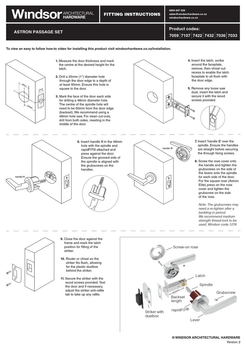
5. Insert the sliding threaded
sleeve into the top shaft,
choosing the correct height
depending on the location of
the mortice hole drilling. The
sliding threaded sleeve can be
adjusted between 55mm to
100mm to the centre of the
square shaft.
6. Fit the rubber weather seals to the
front and back panels.
7. Connect the wire through the door into
the back panel.
0800 607 028
sales@windsorhardware.co.nz
windsorhardware.co.nz
FITTING INSTRUCTIONS
SMART ENTRY LEVER SET
© WINDSOR ARCHITECTURAL HARDWARE
2. Install the mortice lock using the
cropping template provided.
Version 2
Product codes:
Package Contents
Part Description QTY Part Description QTY
A Front Panel 1
B Back Panel 1
C Mortice Lock 1
D Cards 3
E Mechanical Keys 2
F Waterproof Rubber Plates 2
G U-Clip 1
H Striker & Dustbox 1
I Sliding Threaded Sleeves 35x8mm 2
J Sliding Screws 16x5mm 2
K Mortice Screws 10x5mm (for aluminium doors) 4
L Mortice Screws 25x4mm (for wooden doors) 4
M M5x30mm Screws (for door thickness 30-65mm) 1
N M5x50mm Screws (for door thickness 50-65mm) 1
O M5x70mm Screws (for door thickness 50-65mm) 1
P Spindle for door thickness 35-55mm 1
Q Spindle for door thickness 45-65mm 1
R Chuck 1
S Loctite - Threadlock (Windsor code 1276) 1
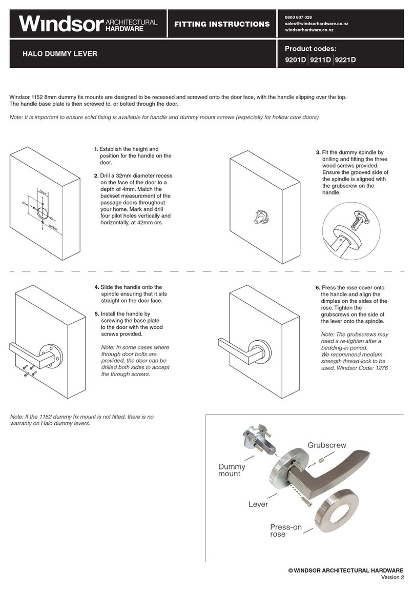
3. Install the spindle into the back of the
lever of the front panel. Insert the split
pin and bend its front end to fix it into
the square shaft (b). Turn the spindle
and square shaft to ensure the small
arrow is pointing towards the hinges (a).
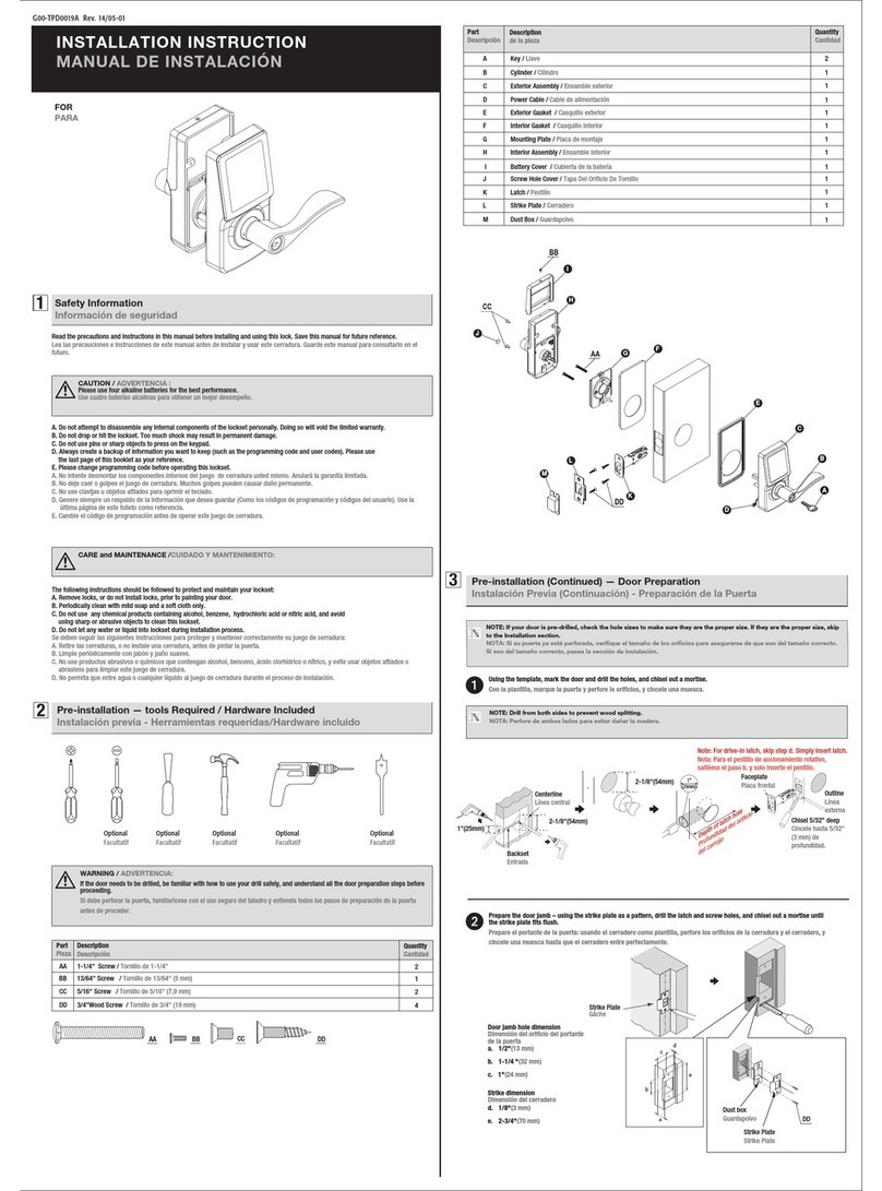
4. Fit the threaded sleeve to the bottom
spigot by turning it counterclockwise
and tighten it.
8. Hold the front panel
against the door face,
sliding the spindle and
threaded sleeves
through the drilled
holes. Install the back
panel by tightening the
screws through the back
panel into the threaded
sleeves. Ensure the
panels are sitting
straight on the door.
9. Insert 4 Alkaline
(AA)1.5V batteries*,
slide the battery cover
onto the interior unit
and tighten it with the
screw provided.
* Warranty void if Alkaline
batteries are not used
a
b
1501 1513
1. Ensure the lever is handed to suit your door. To
adjust the handing, remove the Phillips screw in the
back of the handle by turning it counterclockwise.
Remove the lever and turn it around. Then insert
the screw back into the handle seat and re-tighten
by turning it clockwise*. Both front and back panels
will require this adjustment.
* Recommend using Loctite (Windsor code 1276) on
handle screws.
This product is covered by a one year electronic
warranty and 10 year mechanical warranty.
Measurements
Mortice Locks
Lever Styles
Code Backset* Case
Height*
Case
Depth*
1520 30 174 45
1521 35 174 50
1522 45 174 60
1523 60 174 85
1525 35 218 48
Code Body
Height*
Body
Width*
Lever Protrusion*
1501 310 40 130 78
1511 310 40 73 78
1512 310 40 73 78
1513 310 40 130 78
*measurements in mm
10. To initialise the system
open the cover plate of
the back panel, press
the ‘Reset’ button
pictured for 5 seconds,
then lift the lever to throw
the bolt to complete the
initialisation process.
Use this step only
when resetting the lock
to factory settings. Not
required on first setup.


