VERSION 2 27.03.2019
3
Datas
Dimensions (in mm) 258x140x166
eight 3 kg
Average power for humidification 75 w
Voltage 230V-240V
Average intensity for humidification 0.63 A
Frequency 50/60 Hz
Capacity of humidification 18.2g water/hour at 12°C
Length of power cord 1.5 M
1. AUTOMATIC HYGROMETRY CONTROL
Your ineMaster® air-conditioner controls naturally hygrometry. The hygrometry is then
maintained between 65% and 85% of relative humidity. The excess runs towards a
draining overflow .
Since it depends on the external hygrometry which strongly varies according to the area,
the season and the weather, the hygrometry cannot be completely kept at a set value..
The h gromaster® will assume its full relevance in winter when the temperatures are
low and the relative hygrometry is very low.
In this case, it will be necessary to provide additional moisture thanks to hygromaster®.
Since it is a steam generator, it will produce completely clean moisture.
IMPORTANT: the control of h grometr and the good operation of the air-
conditioner require: -see user guide of the air conditioner inemaster-:
-Complete insulation of the cellar (walls, floor, ceiling, door) with a tight insulating
material
-Perfect continuity of the insulation (no gaps, nor thermal bridges)
-No other ventilation than the one of the air conditioner
-Lack of heat source (fridge, heating pipe…)
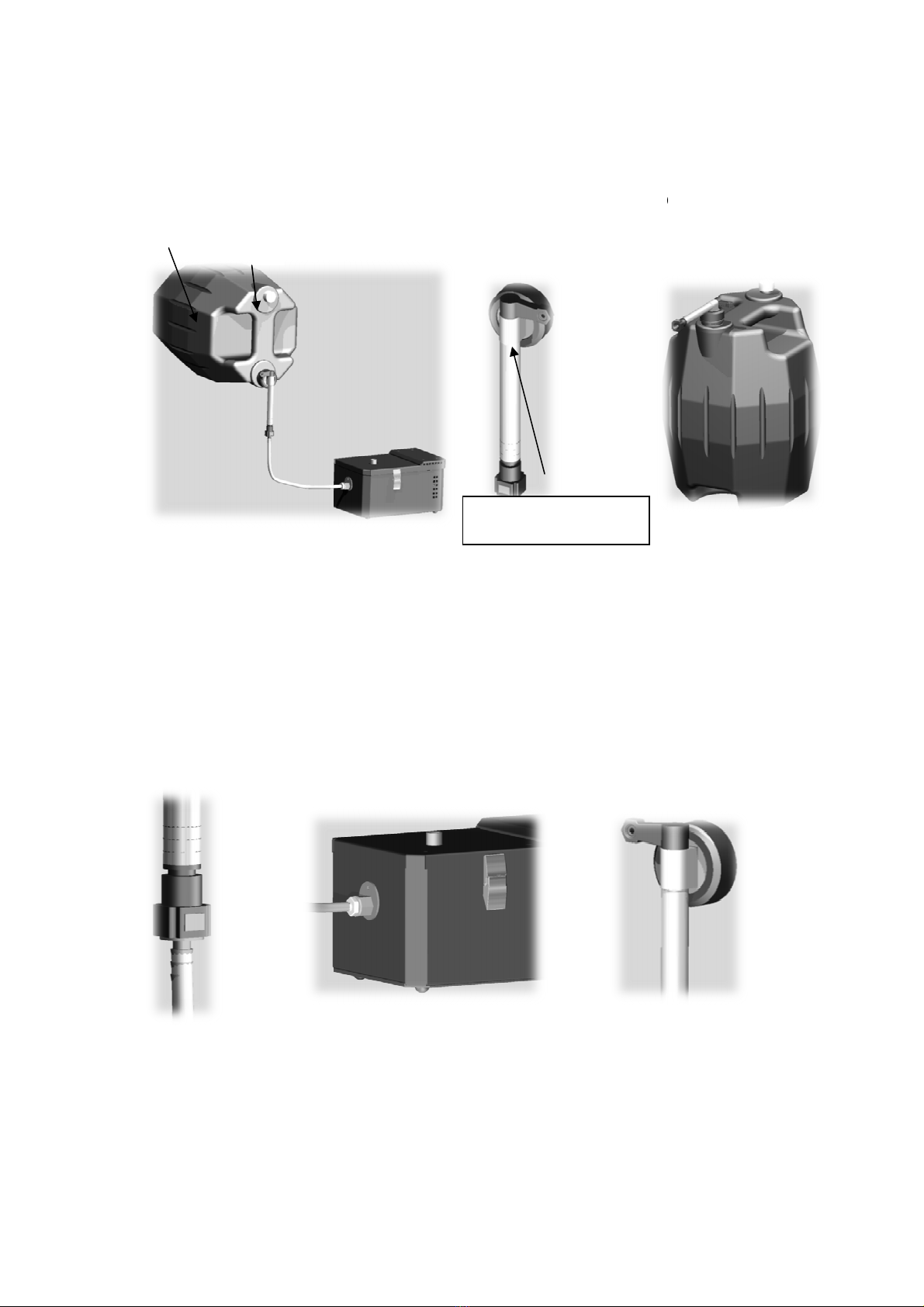
2. INSTALLATION OF THE HYGROMASTER
2.1 H gromaster installation
Your hygromaster can be suspended on a wall using screws in the holes intended
for this purpose or simply placed on the ground or on a stable shelf preferably
more than a meter away from the air conditioner.
However, avoid placing your hygromaster on a wooden support which would
absorb the moisture and could become deformed