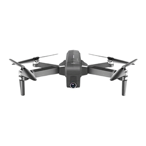
Wingsland Minivet User manual

USER MANUAL
VERSION1.0
Height Changes Your Aesthetic View
Copyright@2015 WINGSLAND All Right Reserved

Support & Service
INTRODUCTION
Thank you for purchasing Wingsland Minivet, you hereby agree with and accept the terms of this
disclaimer and is believed that you have read it thoroughly.
If you have any questions or concerns during your operating, please don’t hesitate to contact
Wingsland Customer service or Wingsland authorized dealer by email or telephone.
Wingsland Customer Service
Incorrect operation causes less likely harm to
users , but risks of getting injured are possible.
CAUTION
WARNING
DANGEROUS
1
Incorrect operation may cause casualties and
other dangers.
Email Address: service@szsungreen.com
Tel: 0086-0755-23123452
Copyright@2015 WINGSLAND All Right Reserved
Incorrect operation may cause Casualties and
other dangers or bodily injury.

Instructions & Cautions
Disclaimer & Warning
Please read this disclaimer and warning carefully before using this Wingsland
product. Once you have begun to use Wingsland product, you hereby agree to
this disclaimer and signify that you have read them fully.
2
Attention before Flight [For safety reason, do not use this product before reading User Manual fully]
Copyright@2015 WINGSLAND All Right Reserved

Limitation of Liability
Battery Usage Notes
3
Attention before Flight [For safety reason, do not use this product before reading User Manual fully]
Copyright@2015 WINGSLAND All Right Reserved

2
4
Copyright@2015 WINGSLAND All Right Reserved
1 Product Profile
1-3 Components of Remote Controller
Aircraft
2-2 Flight Mode
2-3 Flight Battery
3
Remoter Controller
3-1 Install Battery
3-2 Remote Controller Operation
3-3 Display Screen
4
Gimbal and Camera Introduction
4-1 Gimbal and Camera operation
4-2 Camera Setting
5-1 Flight Notes
5-2 Check and Calibrate the Compass
5-3 Flight Operation
5
Flight and Camera Introduction
6
GCS Assistant Software Operation
Contents

1-1Aircraft Assembly
Spin Propellers in the direction with consistence of arrow direction marked on the
aircraft arms (Figure 2).Spin and Fasten Screw Nuts with Assistant Wrench (Figure 1)
Screw Nuts Assistant
Wrench
Install Propellers
Attaching the propellers
according to the correct direction
Install the Display Screen onto Controller Handle
through fastening Screen Lock-Screw. (Figure 3).
Ensure that all propellers are installed correctly and firmly before every flight.
5
1 Product Profile
1
Damaged propellers shall be replaced by Wingsland new ones.
Please use original Wingsland propellers only.
Please use Assistant Wrench to Spin and Fasten Screw Nuts.
Install Display Screen
2
Figu re 1
Figure 2
Figu re 3
Copyright@2015 WINGSLAND All Right Reserved

1. Aircraft
2. Orange LED Indicator
3. Landing Gear
4. Integrated Camera
5. Vibration Absorber Sponge
6. Propeller Lock Screw
7. Propeller
8. Motor
9. GPS Status Indicator
10. Power Button
11. Battery Level Indicator
12. Image Transmitter
13. 3-Axis Gimbal
14. Green LED Indicator
15. Flight Battery
16. Gimbal Assistant port
1. Display Screen
2. Antenna
3. Handle
4. Switch L2
5. Switch R2
6. Switch L1
7. Switch R1
8. Neck Strap Attachment
9. Left Stick
10. Right Stick
11. Trimming Button W1-W4
12. Power Indicator
13. Power Switch
14. Gimbal Joystick Control
15. Battery Compartment Cover
16. Sunscreen Shading
17. Display Screen Indicator
1-2 Components of Aircraft
1-3 Components of Remote Controller
6
18. Charging port
19. Video Output
20. Display Screen Power Button
21. Screen Lock-Screw
22. Screen Bracket
L2-0
L2-1
L1-0
L1-1
Middle Position
R2-0
R2-1
R1-0
R1-1
Copyright@2015 WINGSLAND All Right Reserved
Middle Position Middle Position

Solid Orange + Solid Green + Solid Blue
GPS Initialization completed
(GPS satellites number ≥5)
GPS Stabilized Smooth Mode is available
The default forward direction will be reset automatically after powering on the aircraft each time.
Warning Fast Orange Flashing +Fast Green Flashing, take off prohibited.
Solid Orange+ Slow Green Flashing
Forward Direction Lock Mode
Solid Orange+ Fast Green Flashing
Point of Interest Mode
Slow Orange Flashing + Slow Green Flashing
Compass Calibration mode has been
initiated
2-1 Aircraft Status Indicator
Bottom View
Green indicator
Backward of Aircraft
Blue indicator
Top of Aircraft
Black Shell
Orange indicator
7
2 Aircraft
2-2 Flight Mode
(3) Aerial Photography Mode (L1 to L1- 0 position, L2 to the middle position)
Toggle switch L1 to L1-0 position to activate Aerial photography mode, the fastest speed is limited to 1.2 m/s,
then the operator can focus on the more stabilized aerial photos and videos.
Figure 1
Figu re 2
Copyright@2015 WINGSLAND All Right Reserved
Solid Orange + Solid Green + Blue Flashing
GPS initialization uncompleted
(GPS satellites number <5)
Only Normal Stabilization Mode is available
Forwar d o f A i r c r a f t
Caution
A point

(7) Failsafe Mode (Signal Losing)
When the aircraft fail to receive a signal from the Remote Controller, the aircraft will enter in Failsafe Mode.
The Aircraft will automatically return will automatically control the aircraft to return to recorded home point.
The home point will be set to the location from which the aircraft was launched and
finished GPS initialization.(required GPS satellites number≥5)
Warning
Warning
(6) Low Battery Level Protection Mode
When aircraft battery voltage drops blow 10.8 V, the aircraft will enter in
Low Battery Level Protection Mode. The Flight Orange Indicator will flash
slowly. Meanwhile exclamation mark will appear on the Display Screen,
which shows low battery level warning. The aircraft will land automatically
after approximately 60 second.
The Flight Battery is specially designed for Minivet, built-in battery level indicators which
can display current capacity level.
Main Parameters:
Battery Capacity: 3S, 5200mAh
Battery Voltage: 12.6V (fully charged)
Battery Storage Voltage: 11.4V
Solid Red=Charging
Solid Green=Fully Charge
Flashing=Battery Error
Charging the Flight Battery:
Setup of Battery Level Display:
Press two triangular power buttons with holding for 3 seconds till battery
powering on and the Green indicator will light up. This mode is convenient
for user to view the battery level when flying.
Battery Level Display:
When the battery is powered off, press any button of the battery,
the green LED will light and indicate the current battery level.
This mode is convenient for user to check the battery level.
8
Notice
Notice The battery should be charged in an ideal charging temperature ranges 0~40 .
2-3 Flight Battery
Figure 1
Figure 2
Figu re 3
Enter in Low Battery Level Protection Mode after 60 seconds, the aircraft is descending to land
automatically as soon as possible. All stick commands are available except the Throttle Stick
command during the descent and landing process. The landing point is at the location where
aircraft landed the first time but not the take off point.
The battery temperature may be too high after flight. Do not charge the battery
immediately .Please charge the battery until it cools down to near
room temperature.
Copyright@2015 WINGSLAND All Right Reserved

9
The battery life will be shortened in fully storage status. Please use following method to discharge
the battery to low level if it will not be used for a long time.
Fly in an open field and keep hovering state, landing the aircraft when indicator show that there are
only remaining 2 battery level. Power off the Aircraft and take the Battery out.
Discharge the Flight Battery:
3 Remote Controller
3-1 Install Battery
The Remote Controller is powered by 6pcs AA Alkaline Battery. Open the battery compartment cover (on the back),
install the battery, then close the battery compartment cover (Figure 1).
+
-
+
-
+
-
+
-
+
-
+
-
AA AA
AA AA
AA AA
3-2 Remote Controller Operation
Push the Power switch to the right to Power on the Remote controller.
The Red LED indicator will light.
Push the Power switch to the left to Power off the Remote controller.
The Red LED indicator will be off.
Figu re 1
Figu re 2
Pay attention to the positive and negative.
Power on
Please check and be sure each sticks & switches are on correct positions before powering on
the Remote Controller.
If a continuous beeps from the Remote Controller when powering on, it indicates low voltage
warning. Battery should be replaced immediately.
Powering on the Remote Controller before turning on the aircraft. After every flight,
make sure to remove the aircraft battery firstly, then power off the Remoter Controller.
Copyright@2015 WINGSLAND All Right Reserved
The Remote Controller features a number of aircraft control function as well as controlling tilt
movement of camera, such as record videos, capture photos, adjusting camera setting. The Remote
Controller system operate at 2.4 GHz and has 10 Channels Transmission
Do not using the used and unused
battery together.

10
L1-Middle Position: Stabilized Smooth GPS Mode. This mode has A/B type:
A. Stabilized Smooth GPS Mode: Outdoor and strong GPS signal (GPS satellites ≥5).
B. Normal Stabilized Mode: Indoor or Outdoor but weak GPS signal (GPS satellites <5).
L1-1 Position: Automatic Return-to-Home Mode
L1-0 Position: Aerial photography Mode
(2) L1 Mode Control Switch (3-position switch)
Copyright@2015 WINGSLAND All Right Reserved
Landing the aircraft when ready Trimming operation. After finishing it,
take off the aircraft to check the consequence. Repeat above-mentioned
operation to get an ideal result.
Lock the Trimming Button when finished the Trimming neutral point
setup operation to avoid touching it.
It is recommended that calibrate Trimming Neutral Point via PC
operation. Under nonemergency condition, do not use the Trimming
Button to calibrate the trimming neutral point.
Copyright@2015 WINGSLAND All Right Reserved

11
To avoid of improper operation, the default factory is lock mode.
Unlock procedures are as follows:
Lock Trimming Button Method: Repeat the operation above.
1
2Power off the Remote Controller.
3
4Power on the Remote Controller.
5
(8) Link between the Remote Controller and Receiver
The link between Remote Controller and aircraft has already established so you can initially skip this
procedure. If you ever replace the Remote Controller, re-establishing the link is required. Link procedures
are as follows:
1Be sure the Aircraft is powered off.
2Power off the Remote Controller.
3Press down W2 and W3 simultaneously and hold (Figure2).
4Power on the Remote Controller.
5Release two switches until the Remote Controller indicator blinks.
6Power on the Aircraft.
Remote Controller indicator stops flash and keep solid lighting.
7
(9) How to Operate Remote Controller
The Mode 1 and Mode 2 of the Remote Controller can be changed through Trimming Button.
Basic Flight Operation see below:(Figure 1),(Figure 2),(Figure 3),(Figure 4).
Left Stick Right Stick
Unlock Trimming Button Mode:
Figure 1
Figu re 2
Be sure the Aircraft is powered off.
This indicates that the link has been successfully established.
7
Copyright@2015 WINGSLAND All Right Reserved
6Power on the Aircraft.
7
Press W1 down and W2 left simultaneously and hold (Figure1).
Two beeps indicates that unlock has been successfully finished.
Toggle switch L2 to L2-1 position to activate Forward Direction Lock Mode when flying far from
distinguishing nose direction of aircraft, making flight direction control easily. Enable this
operation only with stabilized smooth GPS Flight Mode.
Toggle switch L1 to L1-1 position to activate the Return-To-Home Mode when
you fail operate or under possible difficulties. The flight control system will automatically
control the aircraft to return to Home Point and land to reduce injuries and damages.
Enable this operation only with stabilized smooth GPS Flight Mode.

Model 2
Caution
12
Figure 1
Figure 2
Figure 3
Figure 4
Figure 1
Figure 2
Figure 3
Figure 4
When hovering, the aircraft is deviated from the hovering point. The Remote Controller Neutral
point recalibration is needed.
Left Stick Right Stick
Nose
Direction
Copyright@2015 WINGSLAND All Right Reserved
Nose
Direction
Nose
Direction Nose
Direction
Nose
Direction Nose
Direction
Nose
Direction Nose
Direction
Model 1
Caution

13
(11) Remoter Controller Indicator Information
Power LED Indicator
Working Mode: Solid Lighting
Remote Controller Link Calibration Mode: Fast Flashing
Sound Indicator
Power on the Remote Controller: there will be one indicator beep when the Remote Controller is powered on.
Continuous beep indicates low voltage level warning, replace the battery immediately.
Unlock Trimming Mode successfully: one beep.
Lock Trimming Mode successfully: one beep.
Switch between Mode 1 and Mode 2: One beep indicates Model 1.
Two beep indicate Mode 2.
Trimming Buttons Indicator
Adjustments of Trimming Button: one beep.
Trimming Maximum: two fast beeps.
Trimming Neutral Point: two slow beeps.
(10) Switches between Mode 1 and Mode 2
Power Indicator Position
Change the control mode with Trimming Button.
Procedures are as follows:
Notice Use the PC to calibrate the Throttle Neutral Point after this Mode Switches.
1Be sure the Aircraft is powered off.
2Power on Remoter Controller.
3Press 4 Trimming Buttons simultaneously as Figure 1 shows.
4
The Mode Switches have been calibrated successfully when
3-3 Display Screen
The Display Screen is equipped with 5.8G image receiver and built-in charge/discharge battery.
The Display Screen can display the view of the camera and flight parameters in real time.
(1)Display Screen Diagram (Figure 1),(Figure 2)
Power Button
Charging Indicator
Charging Port
Satellite Signal
Aircraft Battery
Indicator
Fight Height
Fight Speed
Fight Distance
Fight Position
Figure 1
Figu re 3
Figure 1 Figure 2
Trimming Mode should be in lock state.
hear sound of beep. One beep indicates Model 1.
Two beeps indicate Mode 2.
Copyright@2015 WINGSLAND All Right Reserved

14
(2)Charge the Display Screen
The Display Screen built-in Battery can be charged with PC or
mobile charger and connect to the charging port (Figure 1). The
Display Screen Indicator LED displays RED to tell the charging
status. The battery is fully charged after LED turns Blue.
(3)Display Screen Switch
Press Power Button for 3 seconds to
power on the Display Screen.
(4)Switch Channel
When Display Screen is interfered, the operator can press Display Screen Button rapidly once to switch Display
Screen channels. A total of eight channels for choice. Change procedure are as shown below:
1Power on Display Screen.
2Press Power Button once to switch its channel.
3Power on aircraft.
4Pressing down the button to change the channel,
5Power off aircraft. Turn off Display Screen, switch is finished.
4 Gimbal and Camera Introduction
(1)Camera Memory
Supported Micro-SD card with 64G.The camera would store high definition image. Micro-SD card with
over-8G and Class 10 is recommended due to store high definition photos and videos.
4-1 Gimbal and Camera Operation
(2)Gimbal Operation
The Gimbal Joystick controls the pitch of the 3-Axis Gimbal (Figure 1).
The gimbal can control the tilt movement of the camera within 90 degree range.
Gimbal Conrol
Joystick
(3)Camera Operation
Toggle R1 switch to R1-1 Position, flip R2 switch once,
takes a single capture.
Toggle R1 switch to R1-0 Position, flip R2 switch once
to start recording video.
Then flip once again to stop recording. Cyclic operation
between begin to stop mode.
Channel+
Channel -
Indicator 图传盒
Channel 1 is the factory default setting. Pressing down the button can switch the channel.
Figure 1
Figure 1
Figure 1
Figure 1
The screen will display the channel number.
until high definition image appears.
Copyright@2015 WINGSLAND All Right Reserved
Press Power Button again for 3
seconds to power off the Display Screen
The 3-axis stabilized Gimbal can provide a steady platform for integrated high-definition camera.

15
4-2 Camera Setting
(3)Read the Video and Photo
1Insert Micro-SD card to SD card reader, then connect with the computer via USB cable.
2A new magnetic Disk will appear, click and open it.
3Two folders in the new magnetic Disk: named [MOVIE] stores Videos files,
Select Submenu: move Gimbal Joystick up and down.
Enter/ playback menu: move Gimbal Joystick left and right.
Confirm Button (Confirm the Setting), toggle R2 switch.
Settings on Operate Interface
Mode Switch
1
2
2
Under record mode (Figure 7),
move the Gimbal Joystick to
left, operator can change to
the Capture parameter setting.
Move the Gimbal Joystick
to adjust secondary option
menu setting such as Resolution,
Circle Capture operate, HDR etc.
Move the Gimbal Joystick to right to
enter the selection of parameters.
Toggle R2 switch to confirm.
Move the Gimbal Joystick to left to
return back to previous menu.
Enter in Capture Parameters Setting
Interface by moving Joystick to left
1/2
A
你
HDR
1/2
HDR
视频
46
HDR
720P 1280 X 720
WVGA 848 X 480
VGA 640 X 480
1080FHD 1920 X 1080
HDR
1/2
HDR
Gimbal Joystick
Control
Switch R2
Switch R1
(1)Camera Setting via Remote Controller
(2)Parameters Setting
Enter in Record Mode Setting via toggling the R1 switch from R1-0 position to R1-middle position.
Gimbal Joystick is used for choosing the menu and parameters while use R2 switch to confirm this.
Enter in Capture Mode Setting via toggling the R1 switch from R1-1 position to R1-middle position.
Gimbal Joystick is used for choosing menu and parameters while toggle R2 switch to confirm this.
Video Parameters Setting
Photo Parameters Setting
while named [PHOTO] stores Photos files.
Copyright@2015 WINGSLAND All Right Reserved
Resolution
Loop recording
Time-lapse Record
Video
HDR
1/2
HDR
Resolution
Loop recording
Time-lapse Record
Video
5
Video
HDR
1/2
HDR
视频
HDR
1/2
HDR
Resolution
Loop recording
Time-lapse Record
Video
7
Setup
Date / Time
Auto Power Off
Beep Sound
Language

5 Flight
16
5-1 Fight Notes
(1)Flight Environment Requirements
(2)Flight Limits and No-Fly Zones
5-2 Check and Calibrate the Compass
Only fly in open areas without tall buildings surrounded. Metal and steel structures will affect GPS system and
reduce stabilization of aircraft.
Do not use aircraft in severe weather conditions. This includes wind speed exceeding 10m/s, snow, rain and fog.
Avoid high voltage power lines, where will affect compass.
Avoid base station, which will affect control of aircraft.
Be careful when flying at altitudes greater than 5000m above sea level, motor system will be affected.
Within visual distance, and fly far from crowds.
Every nation and region have their own regulations for using aircraft, learn more and abide details of local
laws before flying.
Do not use aircraft in airport and dense crowds.
Control aircraft within 120m altitude and 250m level.
(1)Preflight Checklist
The transmitter battery and flight battery are fully charged
Each switch of Remote controller to be on correct position.
Trimming Propellers and Screw Nuts in the right direction with consistence of arrow direction .
Be sure fasten Screw Nuts with assistant wrench.
Micro-SD card are inserted correctly.
Gimbal and Camera working normally after powering on.
Motors can work normally after powering on.
Display Screen can show high quality image. Flight data is all right.
(2)Calibrating the Compass
Flip L1 switch for
5times or more
Horizontal-rotating Aircraft
Indicators Fl ashin
Copyright@2015 WINGSLAND All Right Reserved
Make sure to calibrate the compass when you flight for the first time or at a new flight location.
After powering on the controller and aircraft, rapidly flip the L1 switch from the fully up to the fully down
position for at least 5 times until the 4 LED indicators beneath the arms of aircraft turns slowly flashing
for the compass calibration mode being initiated.
Holding the aircraft horizontally, clockwise rotate aircraft 360 degree on its center axis for 4 times or more ,
until the 4 LED indicators beneath the arms of aircraft stop flashing for the complete of compass calibration.

5-3 Flight Operation
( In an open area and strong GPS Signal is recommended)
Nose
Direction
GPS status indicator
Throttle Stick/Ascend(Slowly)
(2) Landing (Outdoor)
Operate in the outdoor and make sure GPS signal is sufficient.
17
Left Stick/Descend(Slowly)
Notice
Notice
Figure 1
Figure 2
Figure 6
Figure 1
Make sure the Remote Controller Power off after Aircraft Power Off.
When the aircraft topple and fall anytime, do not be closed to at once. The operator needs to
maintain the Left Throttle Stick on the lowest position for 10 seconds or more until the aircraft
motors locked, then move to Power off the aircraft.
Copyright@2015 WINGSLAND All Right Reserved
Figure 3
Figure 4
Figure 5
Gently pull the
throttle stick down
Motors Power On
Motors Power On
Motors Power Off
Gently pull the Left Throttle Stick Mode 2down to lower the aircraft. (Figure 1
( ) )
When the aircraft is touching the ground, pull the Left throttle stick (Mode 2) down to the
lowest position and hold for 10 seconds or more until the aircraft motors locked (Figure 5).
Press two triangular buttons on Flight Battery board simultaneously for 3 seconds or more
until the battery indicator turn out. Unplug the Flight Battery out to power off the aircraft.
Press the Display Screen power button for 3 seconds or more to power off the Display Screen.
Power off the controller.
Placing the aircraft on flat ground in an open area, with rear Flight Battery LED indicator facing
toward Operator (Figure 1). Avoid passengers, obstacles, trees, high-voltage lines and possible
electromagnetic interference.
Adjust Display Screen channel. Shorting press Display Screen power button to switch Display
Screen channels, ensure the image on the screen can be displayed clearly. (If image transmission
interfered, switch onto the aircraft transmit channel firstly, then match the Display Screen Channel).
Wait for 1 minute or more when flying for the first time at a new location, until the upper side of aircraft
GPS status indicator Blue LED (Figure 2) stop flashing.
Pulling both control sticks to the bottom inside or outside corner simultaneously to power on the motors
(Figure 3 or Figure 4). Release the control sticks to center position once the motors start.
Drive left throttle stick (Figure 6) up slowly for aircraft ascending (For beginner, the flight altitude controlled within
5-10M is recommended)
When the aircraft hovering, please ensure the battery level indicator always facing toward operator .

18
6 GCS Assistant Software Operation
Obtain the latest Firmware from Wingsland website: www.
szsungreeen.com or Windsland authorized dealer, save to
PC. Click the “Firmware Choice” icon on “Firmware” interf
-ace to choose the latest Firmware file.
Click the “Start Updating” icon to upgrade the latest Firmw
-are. Do not disconnect until the upgrade is finished.
(1) Calibrate the Stick Neutral. 1
23
Remote Controller Calibration
After clicking “YES” icon, rota
te Left and Right stick along th
-e maximum radius(Figure 1)
until the below window closes.
If power on the motors during
this process, maintain the Thr
-ottle stick on the lowest posit
-ion until the aircraft motors lo
-cked.
Click the “YES” icon to
start calibration.
Push Left and Right stick to
the central position, then c
-lick “YES” icon.
Figure 1
Remove all propellers.
Download GCS ASSISTANT Software by browsing directly to our company website:www.szsungreen.com
Unzip the zip file and run the WINGSLAND_GCS software.
Connected the Aircraft USB port (close the Aircraft Battery) to PC via USB cable.
Do not power on the aircraft, to avoid damaging the USB port of PC.
Power on the Remote Controller.
Run GCS Assistant software. Choose the “Remoter
Controller” icon on the “State” interface.
Click the “Remote Controller Calibration” icon and P
-rogram Calibration. Operate the Remote Controller
according to the prompt, until Calibration finished.
1
2
Firmware Status
ID
SN
FW Ver
Sele ct the Fi rm war e fi le Star t Updat e
Engl is h
Firmware Status
Attitude Re mote Co nt rol
Engl is h
Cali br at io n RC
3D
RC Dat e
Stabil iz ed m od e
Hot spot ci rcle mo de Sta nd ar d
Hovering mo de Return to Launch
Care fr ee m od e
Copyright@2015 WINGSLAND All Right Reserved
WINGSLAND_GCS Software has some very practical functionality, such as:
Firmware Upgrade, Neutral Point Calibration of Remote Controller, Flight Simulator Operation, etc.
You will Calibrate your RC, select Yes
to start, select No exit the process.
NO Yes
Please put all the sticks in the middle
position. Then Click the OK button.
Yes
Circle the sticks to max radius after
clicking OK button within 2s.
Yes
Other manuals for Minivet
2
Table of contents
Other Wingsland Drone manuals

Wingsland
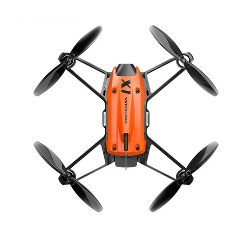
Wingsland X1 User manual

Wingsland
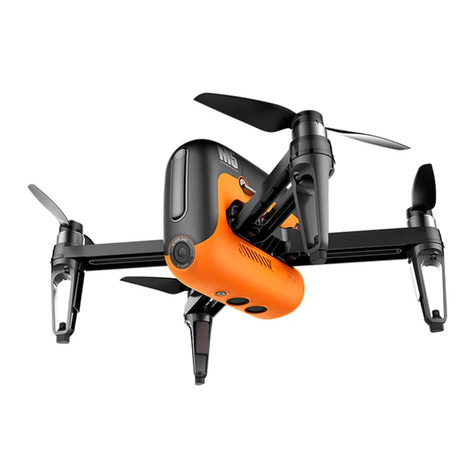
Wingsland M5 User manual

Wingsland
Wingsland S6 User manual

Wingsland
Wingsland X1 Instruction manual

Wingsland
Wingsland S6 User manual

Wingsland
Wingsland X1 Instruction manual

Wingsland
Wingsland R6 User manual

Wingsland
Wingsland S6 User manual

Wingsland
Wingsland Miinivet User manual