5. Cleaning and sterilizing:
Allow sufficient time for burner orifice (7, 7a) to cool down before disassembling or cleaning
the burner head. Check the unit is disconnected and that the gas supply is turned off at the
mains. The burner can be cleaned with customary commercial disinfectants. Additionally, it
is possible to remove the burner head and to clean it separately.
The stainless steel and glass construction allow 100% UV-radiation sterilization and short
time surface flame sterilization.
Attention: Because of the connectors at the back of the unit the backside should not be
sterilized with a flame.
5.1 Burner head disassembly and cleaning:
Allow sufficient time for burner orifice (7,7a) to cool down
before disassembling or cleaning the burner head.
Check the unit is turned off, that the gas supply is
turned off at the mains. Clean the burner head with
customary commercial disinfectants, sterilize it in
an autoclave or wash it in a dishwasher. To remove
the burner head proceed as follows:
Unscrew the burner head screw (12) completely with
the included screwdriver. Turn approx. 8 revolutions
to the left. Now remove the burner head from the device
by pulling it upwards. Reinstallation is performed
in the reverse sequence.
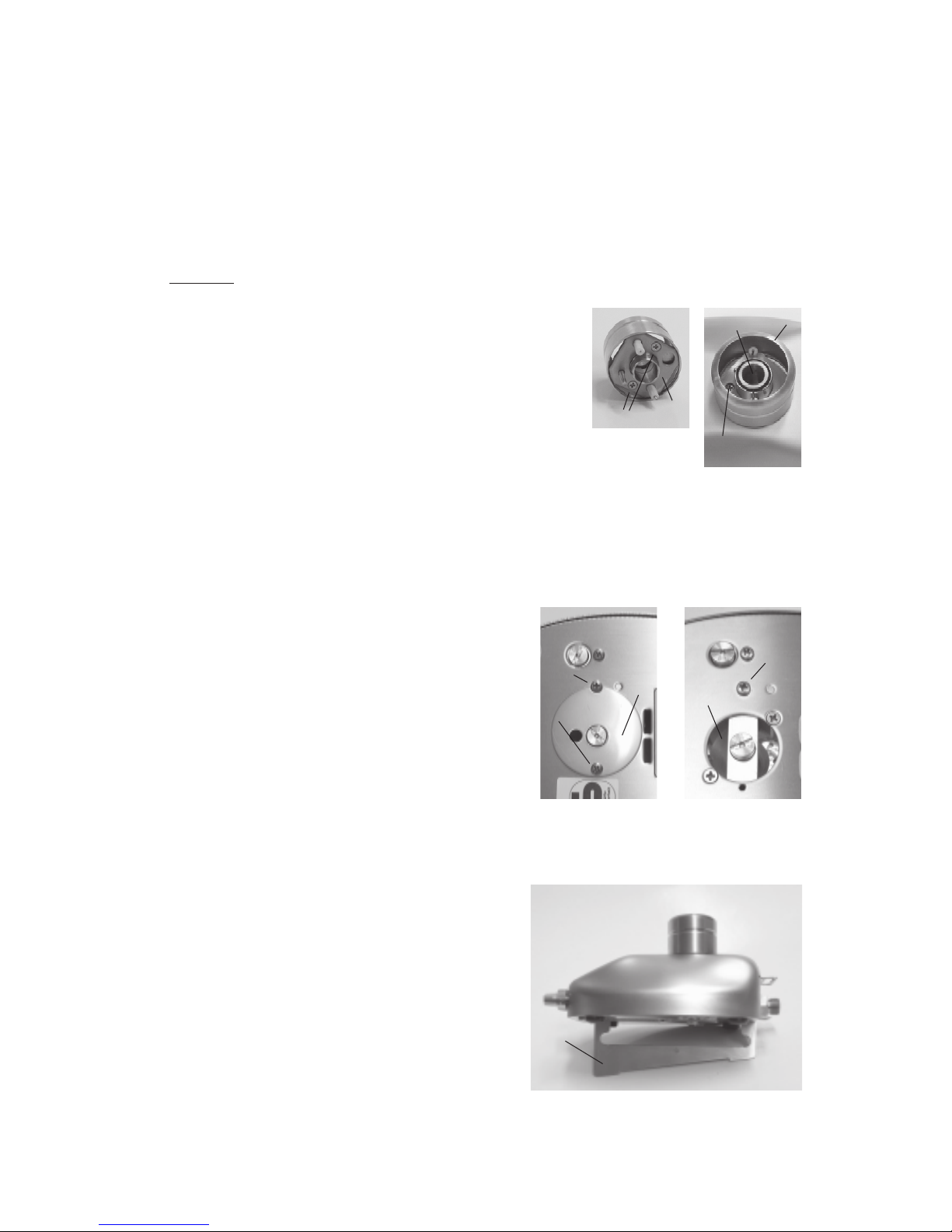
The dismounted burner head can be even dismantled into the individual components for in-
depth cleaning: Unscrew both screws (12a) and take off the base plate (12b) of the burner
head which was fixed by the two screws (12a). After the base plate is removed both electrodes
can be pulled out for seperate cleaning. Reinstallation is performed in the reverse sequence.
5.2 Burner shaft cleaning:
Unscrew the screw (18) completely
with the included screwdriver. Take off the cover (17)
of the burner shaft. Now the burner shaft can
be cleaned or solid substances which have fallen
into the unit can be removed. Reinstallation is
performed in the reverse sequence. Take care that
the notch of the cover fits to the screw (18a).
6. Turbo flame:
If the cover of the burner shaft (17) is removed the
flame is extremely firm and consistent. To take off
the cover of the burner shaft unscrew the screw (18)
completely with the included screwdriver. With an open burner shaft the intensity of the
flame cannot be adjusted by the air knob any longer. During the use of the turbo flame most
of the needed air is taken inside through the open burner shaft. Remounting the cover of
burner shaft. (see paragraph 5.2)
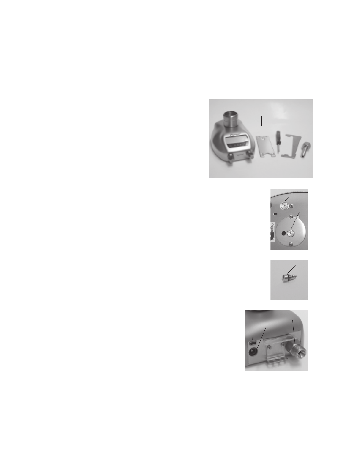
7. Tilt adjustment:
Insert the tilt adjustment (23) into the slots (19)
at the bottom of the unit. The tilt-adjustment can
be used to the left or right side to protect the
burning chamber from contamination when
working with liquids.
23
7a 7
12
12a 12b
18a
17
18
18a open
burner
shaft