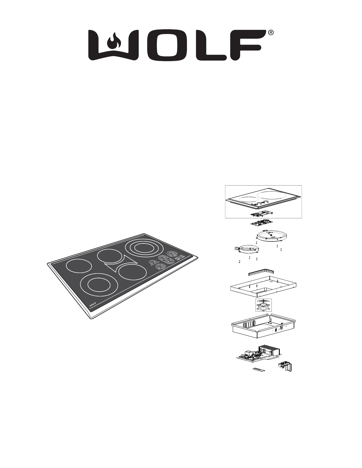
Electric Cooktop -2 General Information
1-3
Section 1 - General Information
Introduction......................................................................... 1-2
Important Safety Information.............................................. 1-2
Technical Assistance.......................................................... 1-2
Table of Contents............................................................... 1-3
Warranty Information.......................................................... 1-4
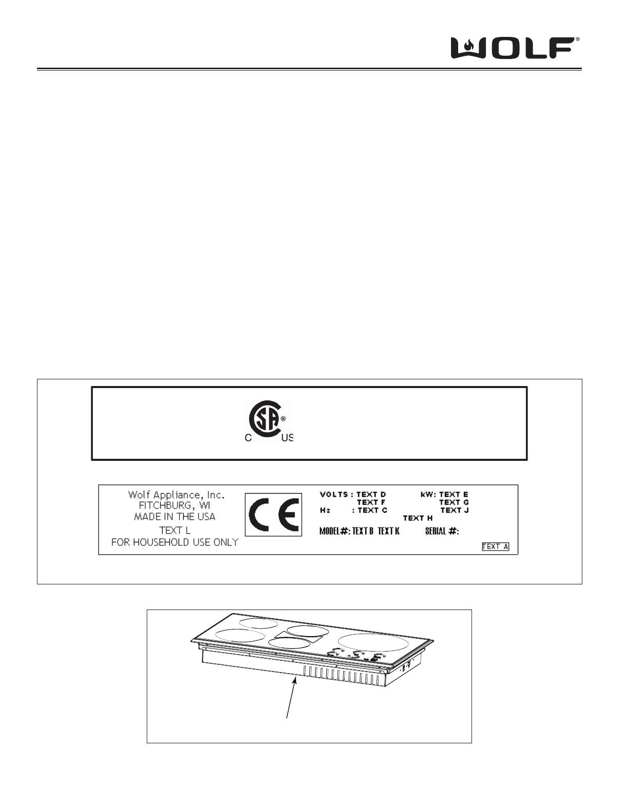
Model Number Key............................................................. 1-5
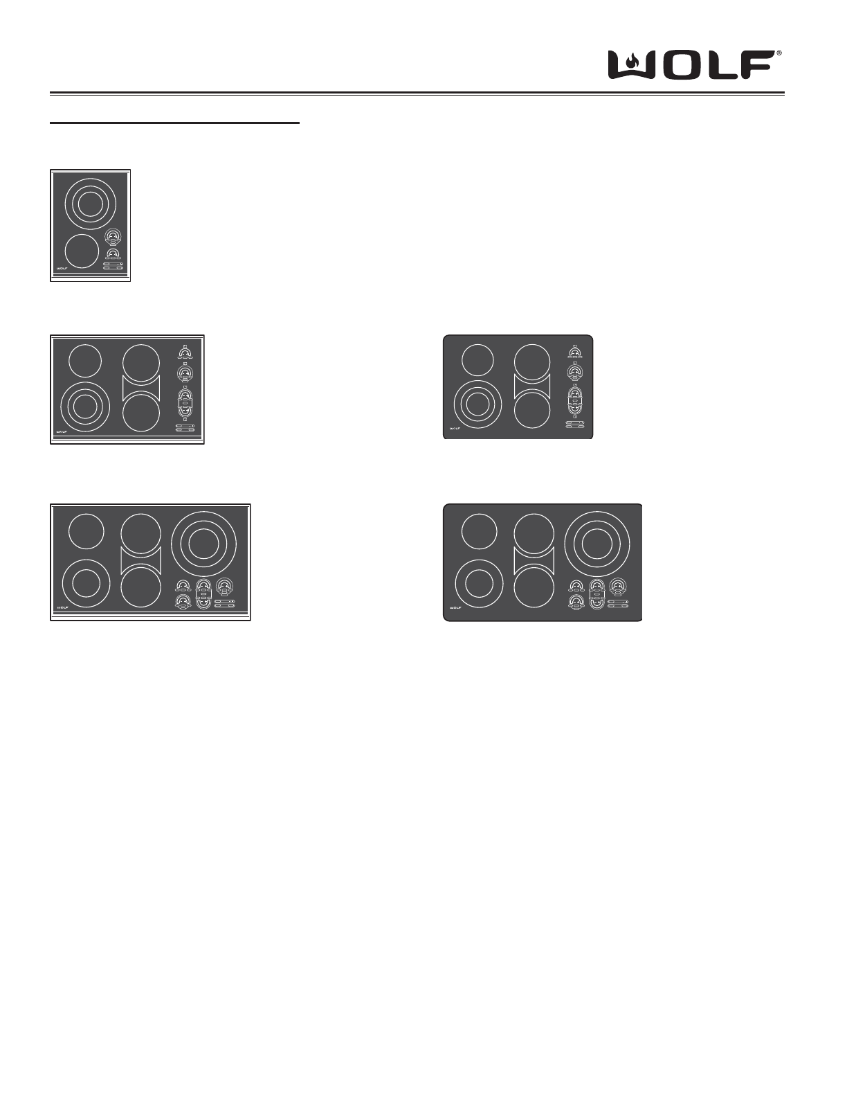
Model Configurations.......................................................... 1-6
Section 2 - Installation Information
Pre-Installation Specifications............................................ 2-2
Electrical Requirements..................................................... 2-2
Counter top Location......................................................... 2-3
Overhead Cabinet Dimensions.......................................... 2-3
Installation Dimensions CT15E........................................... 2-4
Installation Dimensions CT30E........................................... 2-5
Installation Dimensions CT36E........................................... 2-6
Installation Dimensions CT30EU........................................ 2-7
Installation Dimensions CT36EU........................................ 2-8
Installation of Multiple Units............................................... 2-9
Final Installation Procedures.............................................. 2-10
Section 3 - Electronic Control
Electronic Terminology....................................................... 3-2
Cooktop Touch Pads ......................................................... 3-2
CT15E Wattage & Keypad ................................................ 3-3
CT30E, CT30EU & CT30E-208 Wattage & Keypad ......... 3-3
CT36E, CT36EU Wattage & Keypad ................................ 3-4
Universal OFF Key............................................................. 3-5
Control Operation (Modes of Operation) .......................... 3-5
Lock Mode......................................................................... 3-5
Idle Mode........................................................................... 3-5
Showroom Mode................................................................ 3-5
Operation Mode................................................................. 3-6
Element Operation .............................................................. 3-7
Diagnostic Mode................................................................ 3-8
Timer Mode........................................................................ 3-9
Annunciator Setup.............................................................. 3-9
Section 4 - Component Access and Removal
Warnings and Cautions...................................................... 4-2
Major Serviceable Components......................................... 4-2
Glass Top........................................................................... 4-3
Display Board..................................................................... 4-3
Element.............................................................................. 4-4
Upper Pan.......................................................................... 4-4
Power Module.................................................................... 4-4
Cooling Fan (CT30 & CT36).............................................. 4-5
Cooling Fan (CT15)............................................................ 4-5
Generator Assy .................................................................. 4-6
Section 5 -Troubleshooting Guide
Diagnostics Mode.............................................................. 5-2
Diagnostics Tests............................................................... 5-2
Error Mode......................................................................... 5-4
Troubleshooting Chart....................................................... 5-5
TABLE OF CONTENTS
Section 6 - Technical Data
Power Supply Specifications............................................. 6-2
Element Wattage / Resistance .......................................... 6-2
Section 7 - Wiring Diagrams
CT15E Wiring Diagram....................................................... 7-2
CT30E & EU & CT30E-208 Wiring Diagram....................... 7-3
CT36E & EU Wiring Diagram.............................................. 7-4
Section 8 - Parts and Exploded Views
CT15E Parts List................................................................. 8-2
CT15E Exploded Views...................................................... 8-3
CT30E & EU & CT30E-208 Parts List................................ 8-4
CT30E & EU & CT30E-208 Exploded Views...................... 8-5
CT36E & EU Parts List....................................................... 8-6
CT36E & EU Exploded Views............................................. 8-7