5
Dimensions in parentheses are in
millimeters unless otherwise specified.
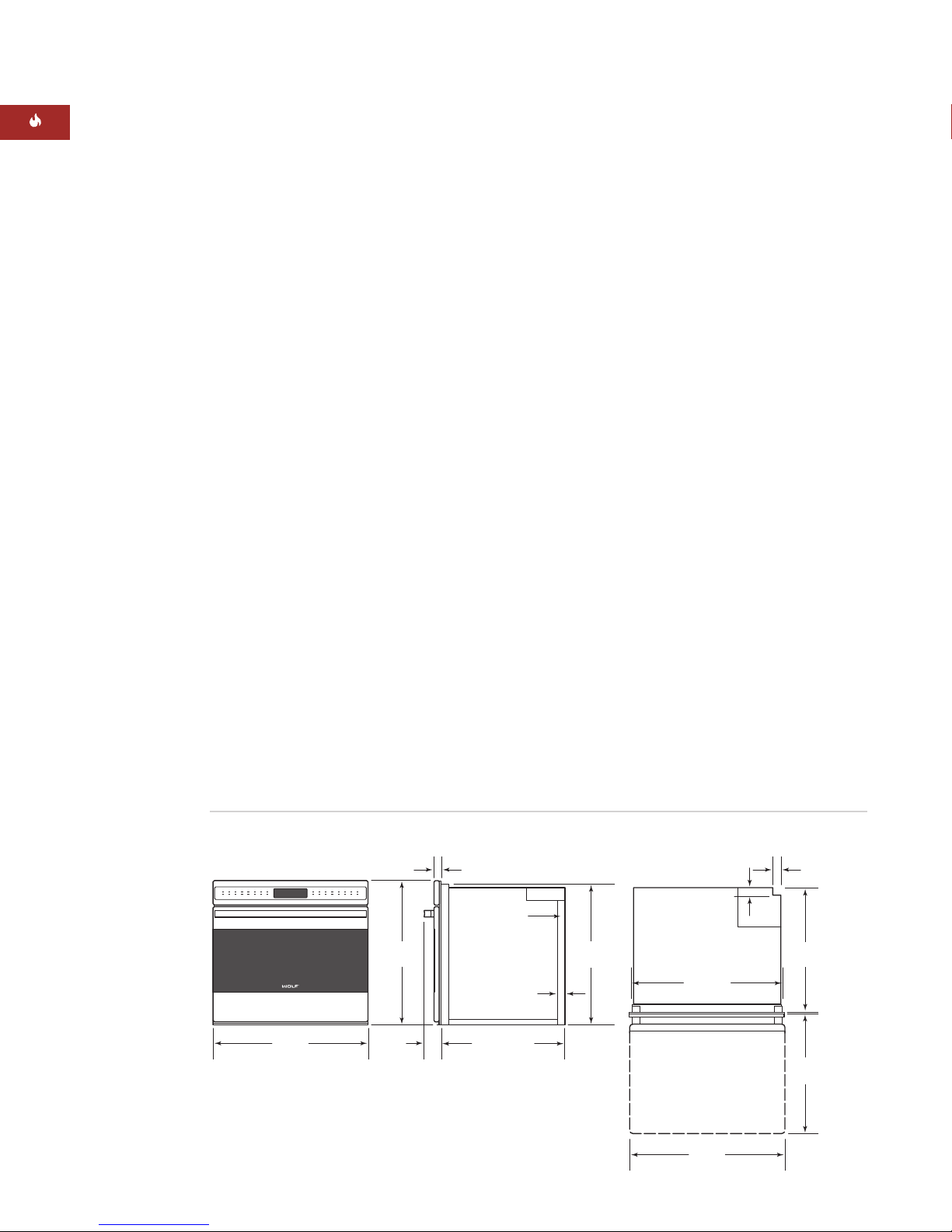
INSTALLATION INSTRUCTIONS
ESERIES BUILT-IN SINGLE OVENS
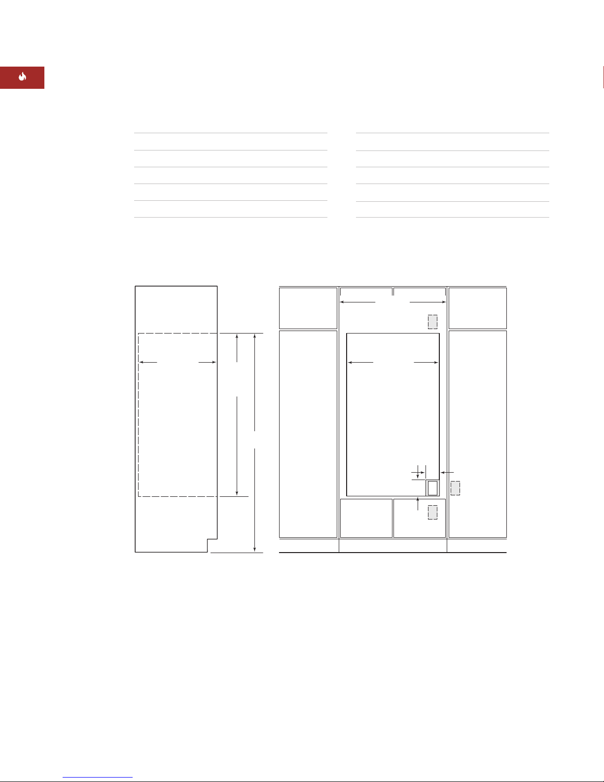
STANDARD INSTALLATION
IMPORTANT NOTE:
For standard installations,
aminimum 24" (610) of usable cabinet depth is
required, or the back panel of the cabinet may
need to be removed for proper installation.
The electrical box must be flush with the back
panel of the cabinet.
For standard installations, the E Series built-in
oven is installed by inserting into cabinetry
from the front. The oven has a face trim on all
four sides and will overlap stiles and rails. The
trim overlaps 1/8"(3) on the bottom, 5/8"(8) on
the top and 3/4"(19) on each side.
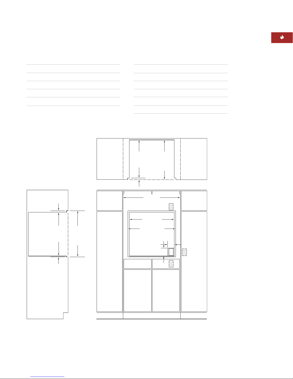
FLUSH INSET INSTALLATION
IMPORTANT NOTE:
For flush inset installa-
tions, a minimum 25" (635) of usable cabinet
depth is required, or the back panel of the
cabinet may need to be removed for proper
installation. The electrical box must be flush
with the back panel of the cabinet.
The flush inset installation requires the built-in
oven to be recessed into the cabinet. A
minimum 33" (838) wide and 25" (635) deep
cabinet is needed if you want the front of the
oven to be flush with surrounding cabinetry.
IMPORTANT NOTE:
For flush inset installa-
tions, the inside edges of the rough opening
must be finished, as they will be exposed
when the oven door is open. These edges
should be stained instead of having a lami-
nated surface, to avoid damage from high
temperatures during self-clean.
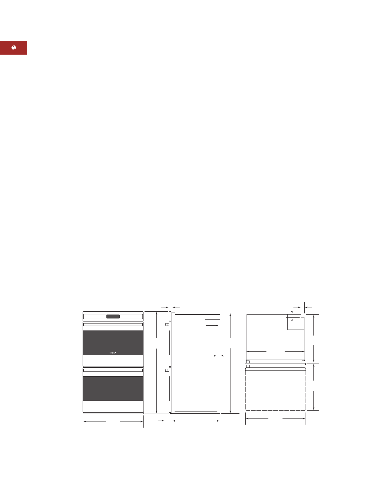
COMBINATION INSTALLATIONS
The Wolf E Series single oven may be installed
below a Wolf 30" (762) induction, electric or
gas cooktop. Unless you are using cabinets
deeper than 24" (610) for a standard installa-
tion or 25" (635) for a flush inset installation,
it is recommended that the electrical supply be
placed in the base cabinet to the right of the
oven. The E Series single oven may also be
installed below a Wolf 36" (914) induction,
electric or gas cooktop.
AWolf E Series single oven may be installed
next to another E Series single oven. You must
allow for a 21/2"(64) space between the oven
rough openings. Also, a separate inner wall is
required for each oven between openings.