Wooden-Gear-Clocks Crescent User manual

The Crescent Clock
Copyright © 2008
Jeffrey A. Schierenbeck

1
Introduction
For hundreds of years, mechanical clocks have served as functional timekeepers. During
that time, clocks have also been treasured for their artistic and aesthetic value. For most clocks,
the artistry involves the shape and ornamentation of the clock’s exterior case. However, these
cases hide the inner beauty of the clock–its mechanical clockworks.
The Crescent clock is a wooden gear clock that is a functional timekeeper with an open
frame which exposes its mechanical elements. All the moving parts are clearly visible. It is
intriguing to watch the seconds and minutes tick away.
It is enjoyable to see and hear this clock running. However, the most enjoyable part of
this clock is the satisfaction gained by assembling the clock yourself, perhaps adding your own
creative touches. And, through the process of building the clock, you will gain an understanding
of the principles that govern how a clock works.
We truly hope you enjoy building your clock. Please contact us if there is any way that
we can help you with your clockmaking project.
Tools and Supplies
Every part necessary to construct your Crescent clock is included in the kit. The
following items will be necessary to build your clock:
• Phillips screwdriver
• small slot screwdriver
• knife
• hammer
• clamps (small spring clamps work well)
• about 4 lbs of metal shot (available from sporting goods or firearms stores)
• wood glue
• sandpaper (150 grit, 220 grit, 400 grit suggested)
• pencil
• 7/16" wrench
Safety
It is your responsibility to use the proper tools and techniques to accomplish this project,
including consulting all owner manuals and label directions for any tools or products used.
This package contains small parts, and should be kept away from young children.
KIT

2
Assembly Tips
1) To remove the parts from the original board, carefully bend the parts out to break the small
sliver of wood that is holding them in place. If necessary, use a knife to free any pieces that were
not completely scored by the laser. Remove any paper or tape from the back of the pieces.
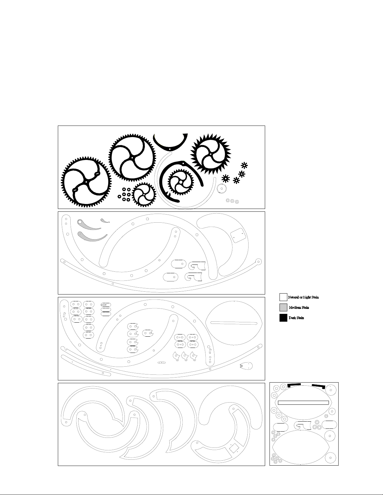
2) You may stain your clock if desired. See the Stain Chart on the next page for a suggested
color scheme. Although it is possible to do all the staining after the clock is assembled (the clock
is easily disassembled), you may find it easier to stain the gears prior to assembly. Since a finish
can hinder glue bond, wait to apply finish to the remaining pieces until the components have
been glued together (suggested sequence for sanding and finishing is included in the step by step
instructions). If you choose to apply a varnish, avoid getting varnish on the contact faces of
the gear teeth and escape lever.
3) A few components require gluing. Glued parts should be clamped while the glue cures.
4) Follow the instructions in order. Carefully complete one step before moving on to the next.
5) Some of the parts might benefit from some light sanding, especially at the breakaway points
where the pieces were attached to the original board. Do not sand the mating surfaces of the gear
teeth. Note that the backsides of some pieces will show residue from the laser cutting operation.
A light sanding will remove this residue, although for nearly all parts this is not necessary
because the residue will not be visible once the clock is assembled. If desired, the edges of the
frame pieces can be sanded to remove the residue left by the laser. The assembly instructions
indicate at what point the various pieces should be sanded.
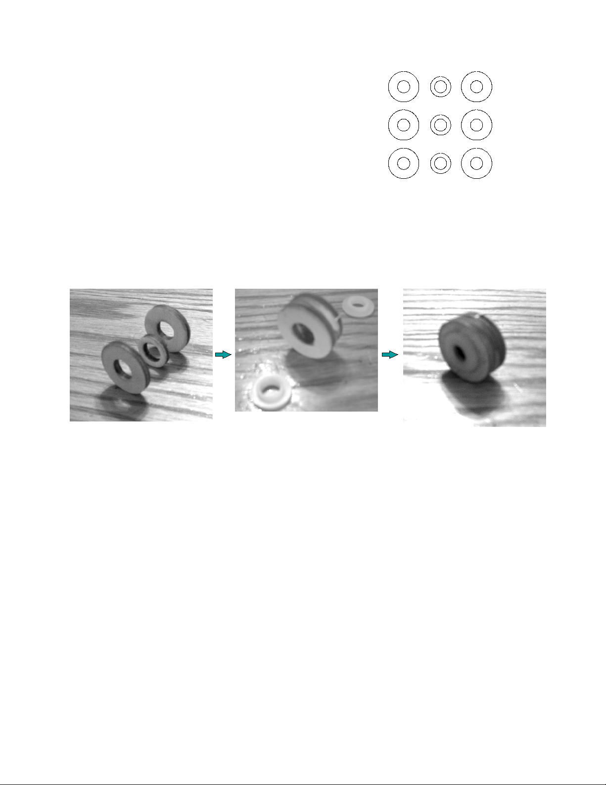
6) It will be beneficial to lubricate a few points with graphite (pencil lead). These points include
the portions of the arbors that spin in the bearings and the contact faces of the escape lever.
7) Some of the parts fit together tightly. It may be necessary to gently tap them together with a
hammer. (Plywood thickness can vary slightly. If the fit seems too tight, some light sanding may
be necessary to insure a proper fit).
8) Once the clock is a assembled and mounted, there will likely be some adjustments required to
get the clock running properly. Follow the suggestions in the ‘Adjusting and Regulating’ and the
‘Troubleshooting’ sections of the instructions.
9) Take your time and enjoy the process!

3
Part List (1 of 3)
1.
64-tooth great wheel
2. 60-tooth middle gear
3. Escape lever
4. Crutch
5. Escape wheel
6. 8-tooth gear [3]
7. 10-tooth gear
8. Minute pipe piece [3]
9. Rachet
10. Dial
11
11. 32-tooth hour gear
12. 30-tooth minute gear
13. Set washer [7]
14. Lower pendulum shaft
15. Front frame inner piece
16. Minute hand
17. Hour hand
18. Second hand
19. Front frame outer piece
20. Weight shell rear face
21. Weight shell cover plate
22. Weight pulley hook piece [2]
23. Weight pulley interior side [2]

4
Part List (2 of 3)
24. Crutch arm
25. Rear frame outer piece
26. Pillar base pieces [8]
27. Rewind pull middle piece
28. Rewind pull outer piece [2]
29. Upper pillar middle pieces [4]
30. Rear frame inner piece
31. Pendulum bob rear piece
32. Pendulum bracket
33. Pillar rear pieces [4]
34. Lower pillar middle pieces [3]
35. Pendulum support plate
36. Upper pillar slotted middle piece
37. Upper pendulum shaft
38. Weight shell front piece
39. Weight shell interior pieces [3]
40. Weight shell front face
41. Weight shell rear piece

5
Part List (3 of 3)
42. Spacer washer [9]
43. Pendulum bob front piece
44. Weight pulley outer piece [2].
45. Weight hook interior piece
46. Pulley wheel side [6]
47. Pendulum bob interior piece
48. Rachet Pawl [2]
49. Weight spool interior divider
50. Weight spool hub
51. Winding spool hub
52. Pulley hub [3]
53. Outer spool sides [2]
1/4" Diameter Dowels
1/2" Pendulum splice pins [2]
3/4" Crutch pin
1" Weight pulley axle
1 1/8" Weight shell rods [2]
2 3/4" Pillar rods [4]
2 15/16" Winding guide axle
2 1/8" Minute arbor
3 5/8" Escape wheel arbor
2 3/4" Escape lever arbor
2 3/4" Middle wheel arbor
4 5/8" Great wheel arbor
Hardware
#4 x ½" screws [6]
#6 x 1" screws [2]
Nylon shoulder washers [16]
19' braided cord
1/4" - 20 x 2 ½" hanger bolt
1/4" - 20 acorn nut
1/4" washer
1/4" x 20 x 1/4" T-nut
drywall anchor
#6 x 1 1/4" screw
#8 washer
1/4" - 20 x ½" thumbscrew

6
Stain Chart
The diagram below indicates which pieces to stain dark if you choose to use a color scheme with darker gears
and lighter frame. Of course, you can use another color scheme, such as light gears and darker frame.
However, you may still find the stain chart helpful for grouping parts together that should be the same color. It
is easiest to stain the gears before they are attached to the arbors. The other pieces (frame, weight shell,
pendulum, etc) can be stained after the necessary components are glued together. The assembly instructions
indicate at which time in the process that finish should be applied to the components.

7
How the Crescent Clock Works
It is helpful to have an understanding of how the Crescent clock works. This insight will be
especially beneficial if troubleshooting is necessary.
The Crescent clock is driven by weight. The weight is hung from a cord that is wound
around the great wheel arbor (shaft). The weight unwinds the cord from the arbor, causing the arbor
to rotate. The gears that are attached to this arbor mesh with a train of other gears, causing them to
rotate as well. When the cord has unwound to a point where the weight has nearly reached the
floor, the clock is “wound” by winding the cord back around the arbor.
The speed at which the weight is allowed to rotate the gear train is regulated by the
pendulum. As the pendulum swings back and forth, it causes the escape lever to rock back and
forth along with the pendulum. The escape lever alternately stops and then releases one of the
wheels in the train (called the escape wheel). These contacts with the escape lever and the escape
wheel teeth generate the “tick-tock” sound of the clock.
The faster the pendulum moves back and forth, the faster the escape wheel (and the entire
gear train) will be allowed to advance. The pendulum swing period is determined by its length (or,
more precisely, the length from its pivot point to its center of gravity). Increasing the pendulum
length increases the time it takes the pendulum to complete its swing. This makes the clock run
slower. Decreasing the pendulum length decreases the time it takes the pendulum to complete its
swing, making the clock run faster. Therefore, adjusting the position of the pendulum bob along the
pendulum shaft controls whether the clock runs fast or slow and provides a means by which the
clock can be made to run “on time.”

8
Pulley Wheel Assembly
Parts (for three identical pulley wheels)
3 - Pulley hubs (#52)
6 - Pulley wheel sides (#46)
6 - Nylon shoulder washers
Assembly Procedure
1) Glue together the three pulley pieces with the smaller diameter hub sandwiched between the two
larger side pieces with all three holes aligned. After the glue has dried, the pulley edges can be sanded
and finish applied. Next, apply a small amount of glue around the rim of the hole in both pulley faces
and insert a nylon shoulder washer. It might be necessary to either press the washer firmly into place
or to tap it into place with a hammer. Be sure the washer seats completely into the hole. Repeat this
process twice to make a total of three identical pulley wheels.

9
Lower Pillar Assembly
Parts 5 - Pillar base pieces (#26 )
3 - Lower pillar middle pieces (#34)
2 - Pillar rear pieces (#33)
2 - 2 3/4" dowels
Pulley wheel (assembled previously)
Assembly Procedure
1) Glue together four of the pillar base pieces (#26). Then glue together the three pillar middle pieces
(#34). Next, glue together the three pillar rear pieces (#26, #33, #33). After the glue is dry, sand the
three pillar subassemblies. Next, glue the three subassemblies together with the two 2 3/4" dowels
inserted through the pillar, making certain that the pieces are oriented as shown below. The dowels
should protrude equally (approximately 1/4") from both faces. Verify that the pulley spins freely.

10
Upper Pillar Assembly
Parts 3 - Pillar base pieces (#26 )
4 - Upper pillar middle pieces (#29 )
1 - Upper pillar slotted middle piece (#36)
2- Pillar rear pieces (#33)
1 - Pendulum support plate (#35)
2 - 2 3/4" dowels
1 - #4 x ½" screw
Assembly Procedure
1) Glue together the ten pillar pieces, in the order shown below (from front to rear,
#26,#26,#29,#29,#36,#29,#29,#26,#33,#33) with the two 2 3/4" dowels inserted through the pillar.
Dowels should protrude equally (approximately 1/4") from both faces.
2) After the glue has dried, sand this completed upper pillar.
3) Attach the pendulum support plate (#35) to the upper pillar with a #4 x ½" screw, centering it in the
recess. The slot in the center pillar piece serves as a pilot hole for the screw.
Slot

11
Frame Assembly
Parts 1 - Rear frame outer piece (#25)
1 - Rear frame inner piece (#30 )
1 - Front frame inner piece (#15)
1 - Front frame outer piece (#19)
10 - Nylon shoulder washers
Upper pillar (assembled previously)
Lower pillar (assembled previously)
Assembly Procedure
1) Glue together front frame pieces (#15, #19). Glue together the rear frame pieces (#25, #30). Make
certain that the pieces are oriented as shown below and that the holes are aligned. Clamp to a flat
surface while glue dries to ensure that the pieces remain flat.
Front Frame Pieces
Rear Frame Pieces

12
2) Sand the frame units.
3) Glue the upper and lower pillars (assembled previously) to the interior side of the front frame.
The protruding dowels engage with the two holes in the frame. Make sure the pillars are oriented as
shown in the photos below.
4) Apply finish to the frame units.
5) With the frame pieces interior face up (as shown below), apply a small amount of glue around the
rim of each of the 3/8" holes in the frames and insert a nylon shoulder washer. It might be
necessary to firmly press into place or to tap in with a hammer. Be sure the washers gets seated
completely into the holes.
Flip the front frame over and likewise insert one shoulder washer into the endmost hole indicated in
the photograph below. Do not insert washers into the remaining holes in the front face of the frame.

13
Crutch Arm Assembly
Parts 1 - Crutch arm (#24 )
1 - 3/4" dowel
Assembly Procedure
Glue the 3/4" dowel into the crutch arm (#24 ). Be sure the crutch arm is oriented as shown below.

14
Pendulum Bob Assembly
Parts 1 - Pendulum bob rear piece (#31)
1 - Pendulum bob front piece (#43)
1 - Pendulum bob interior piece (#47)
1 - T-nut
Assembly Procedure
1) Glue the pendulum interior piece (#47) to the pendulum rear piece (#31), making sure the outer
edges are lined up. Clear any excess glue from the slotted portion. Set the tee-nut in the slot in the
pendulum back with the barrel in the slot and the flat part facing up. Orient the nut so that it falls past
the interior piece and drops all the way down in the slot. Glue the pendulum bob front piece (#43)
onto the interior piece, keeping glue away from the slotted portion. Verify that the T-nut slides freely
along the length of the slot prior to the glue curing.
2) Sand the pendulum bob edges and front face.

15
Pendulum Assembly
Parts 1 - Upper pendulum shaft (#37)
1 - Lower pendulum shaft (#14)
1 - Pendulum bracket (#32)
2 - ½" dowels
1 - 1/2"x 1/4-20 thumbscrew
2 - #4 x ½" screws
crutch arm (assembled previously)
pendulum bob (assembled previously)
Assembly Procedure
1) Sand edges of the two shaft pieces. Glue together the upper and lower pendulum shafts, with the ½"
dowels glued into the holes, pinning the pieces together. Make sure the upper shaft piece (#37) is on
top of the lower shaft piece (#14).
2) Touch up sand the pendulum edges where they overlap..
3) Drive the two #4 x ½" screws into the predrilled holes in the pendulum bracket (#32).
#37
#14

16
4) Sand the pendulum bracket (#32) and glue it into the upper pendulum shaft, with the screw tips
pointing toward the lower portion of the pendulum.
5) Lay the pendulum shaft on top of the crutch arm (assembled previously), aligning the two predrilled
pilot holes. Attach the crutch arm to the pendulum shaft with a #4 x ½" screw. The screw should be
tight enough to hold the crutch arm in place (the exact position will be adjusted later).
5) Flip the pendulum shaft over and rest it on the back side of the pendulum bob (assembled
previously). Attach the shaft with the thumbscrew engaged with the t-nut in the bob. Tighten snugly
enough to keep the bob in place (the exact position will be adjusted later).
6) Apply finish to the pendulum unit.

17
Weight Shell Assembly
Parts 1 - Weight shell front face (#40)
1 - Weight shell front piece (#38)
3 - Weight shell interior pieces (#39)
1 - Weight shell rear piece (#41)
1 - Weight shell rear face (#20)
1 - Weight shell cover plate (#21)
2 - 1 1/8" dowels
2 - #4 x ½" screws
Assembly Procedure
1) Glue the weight shell pieces together. The pieces are ordered from front to back and oriented as
shown below (40,38,39,39,39,41,20), with the two dowels inserted in the holes on either end of the
shell. Note that the cutouts of the interior pieces have a curved end and a straight end; make sure the
ends are oriented as shown below.
2) After the glue is dry, sand and finish the weight shell and cover (#21).
3) Carefully fill the shell with metal shot. As the shot nears the rim, jostle the shell back and forth to
settle the metal shot. Use two #4 x ½" screws to secure the weight shell cover (#21) to the weight
shell.

18
Weight Pulley Assembly
Parts 2 - Weight pulley outer piece (#44)
2 - Weight pulley hook piece (#22)
2 - Weight pulley interior side piece (#23)
1 - Weight hook interior piece (#45)
1 - 1" dowel
pulley wheel (assembled previously)
Assembly Procedure
Glue together the two outer piece pairs. Glue together the three hook pieces. After the glue has dried,
sand these three subassemblies. Next, sand smooth the center portion of the 1" dowel. Insert the
dowel into the pulley wheel; sand more as needed to ensure that the wheel spins freely. Coat the
middle portion of the dowel with graphite (pencil lead). Finally, glue together the three subassemblies
with the pulley dowel engaged into the two holes on the inside faces of the hook unit sides. Verify that
the pulley spins freely. Apply finish to the weight hook. Verify again that the wheel spins freely.

19
Weight Spool Assembly
Parts 1 - Rachet (#9)
2 - Outer spool sides (#53)
1 - Weight spool interior divider (#49)
1 - Weight spool hub (#50)
1 - Winding spool hub (#51)
cord
Assembly Procedure
1) Thread the winding cord through the small hole in spool divider (#49). Pull a few feet of cord
through the hole so that it does not slip back through during spool assembly.
2) Glue the rachet (#9), outer spool sides (#53), spool interior divider (#49), weight hub (#50), and
winding hub (#51) together in the order shown. Be careful to orient the rachet teeth as shown.
Use a piece of 1/4" dowel or a drill bit to help align the pieces and to clear the center hole of excess
glue (remove dowel before glue sets). It is critical that the glue bond between all of the spool
pieces are solid–ensure adequate glue coverage and clamp time.
3) Pull the cord through the spool divider (#49) until there is approximately 12 feet of cord on the
rachet side of the spool divider.
4) If desired, apply finish to the weight spool (if desired, cord can be removed to stain and then
reinserted with tweezers or similar tool).
12'
Table of contents