Worldcast Systems AUDEMAT FM PROBE User manual

AUDEMAT FM Probe 1.2.x User Manual –07/2021
Page 2
WorldCast Systems SAS - 20, avenue Neil Armstrong –33700 Merignac –Bordeaux Métropole (France)
+33 (0)5 57 928 928 –contact@worldcastsystems.com –www.worldcastsystems.com
CONTENTS
1. INTRODUCTION ............................................................................................................................................4
1.1. General information .....................................................................................................................................4
1.1.1. About WorldCast Systems .....................................................................................................................4
1.1.2. About the Audemat FM PROBE .............................................................................................................5
1.2. Options..........................................................................................................................................................5
1.2.1. Software options....................................................................................................................................5
1.3. Before you start ............................................................................................................................................6
1.3.1. Safety warning .......................................................................................................................................6
2. PRODUCT PRESENTATION.............................................................................................................................8
2.1. Specifications ................................................................................................................................................8
2.2. Network configuration................................................................................................................................10
2.3. List of the included accessories ..................................................................................................................11
2.4. Front panel..................................................................................................................................................11
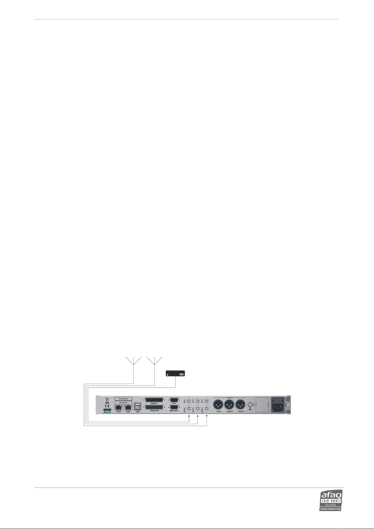
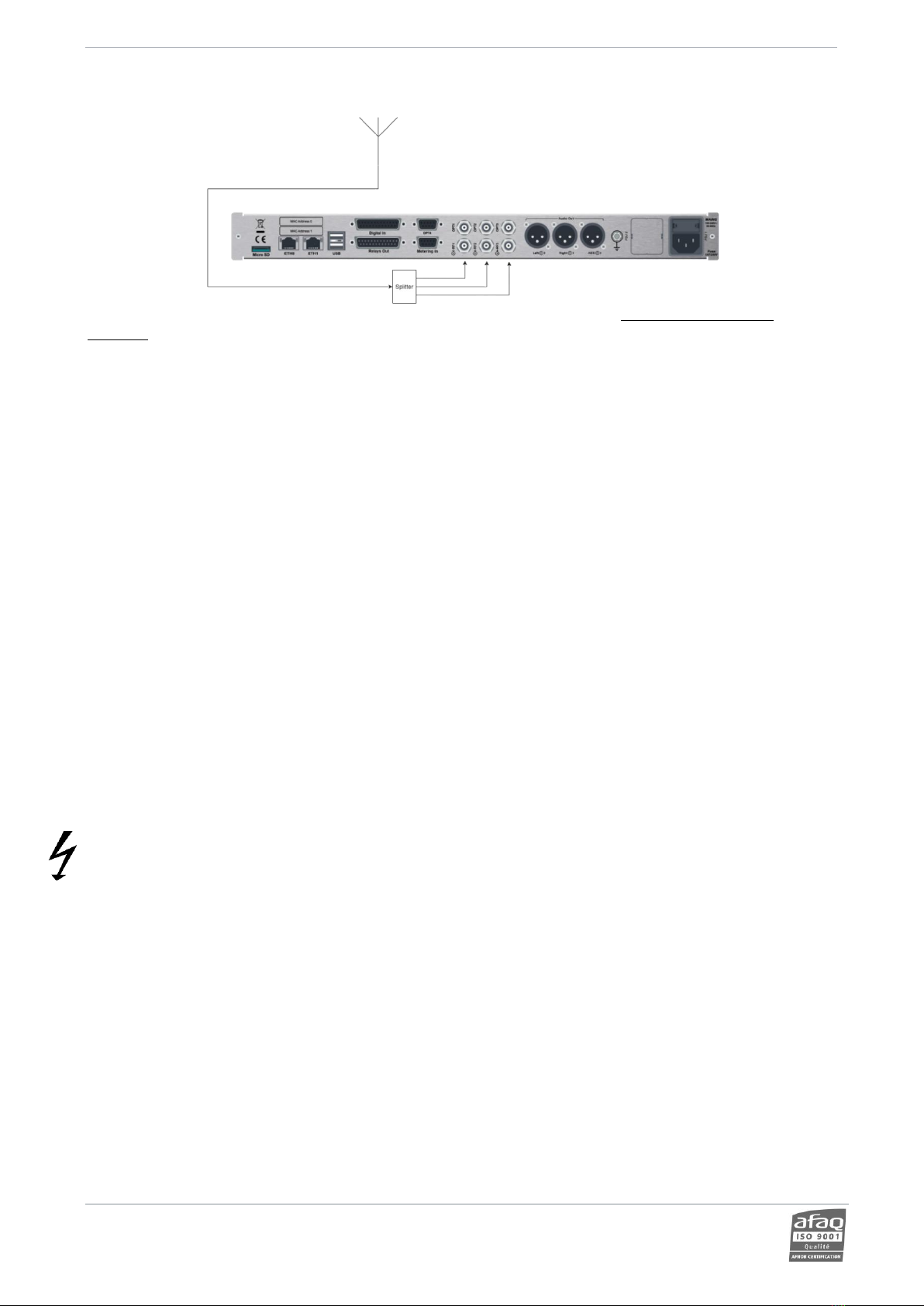
2.5. Rear panel...................................................................................................................................................11
3. GETTING STARTED WITH THE AUDEMAT FM PROBE...................................................................................12
3.1. Connecting to the network.........................................................................................................................12
3.2. Configuring the AUDEMAT FM PROBE using the embedded website ........................................................13
3.2.1. Connecting to the web site..................................................................................................................13
3.2.2. Selecting channels to monitor .............................................................................................................13
3.2.3. Viewing channel status and readings ..................................................................................................14
4. WORKING PRINCIPLE ..................................................................................................................................15
5. FRONT PANEL APPLICATION .......................................................................................................................19
5.1. Presentation................................................................................................................................................19
5.2. Working principle........................................................................................................................................19
5.3. Structure of the menus...............................................................................................................................20
5.3.1. Synoptic view.......................................................................................................................................20
5.3.2. Main Menu ..........................................................................................................................................20
5.3.3. Status Menu.........................................................................................................................................21
5.3.4. Readings Menu ....................................................................................................................................21
5.3.5. Listen to audio Menu...........................................................................................................................21
5.3.6. System Menu.......................................................................................................................................22
5.3.7. About Menu.........................................................................................................................................23
6. THE WEB APPLICATION...............................................................................................................................24
6.1. Warning ......................................................................................................................................................24
6.2. Connecting to the embedded web site.......................................................................................................24
6.3. Application overview ..................................................................................................................................25
6.4. Monitoring ..................................................................................................................................................26
6.4.1. Overview..............................................................................................................................................26
6.4.2. General status and real time readings.................................................................................................27
6.4.3. RDS data...............................................................................................................................................29
6.4.4. History measurements.........................................................................................................................30
6.4.5. Channel setttings .................................................................................................................................31

AUDEMAT FM Probe 1.2.x User Manual –07/2021
Page 3
WorldCast Systems SAS - 20, avenue Neil Armstrong –33700 Merignac –Bordeaux Métropole (France)
+33 (0)5 57 928 928 –contact@worldcastsystems.com –www.worldcastsystems.com
6.5. Managing channels.....................................................................................................................................33
6.6. Real time.....................................................................................................................................................37
6.7. Event log .....................................................................................................................................................38
6.8. System configuration ..................................................................................................................................39
6.8.1. System / Global Settings ......................................................................................................................39
6.8.2. System / IP Settings .............................................................................................................................41
6.8.3. System / SNMP/SMTP..........................................................................................................................43
6.8.4. System / Users .....................................................................................................................................46
7. TELNET COMMANDS...................................................................................................................................47
7.1. Working principle........................................................................................................................................47
7.2. List of commands........................................................................................................................................49
APPENDIX A: HOW TO USE SNMP COMMANDS WITH THE AUDEMAT FM PROBE ..........................................56
A.1. Download the MIB file from the AUDEMAT FM Probe unit .......................................................................56
A.2. Parameters for identification of the Audemat FM Probe...........................................................................57
A.3. RF parameters ............................................................................................................................................58
A.3.1. Channel Table......................................................................................................................................58
A.3.2. Active Alarm table (dynamic) ..............................................................................................................59
A.3.3. Readings ..............................................................................................................................................60
A.3.4. Alarms..................................................................................................................................................62
A.4. Settings .......................................................................................................................................................64
A.5. General configuration.................................................................................................................................72
APPENDIX B: OPTIONAL INPUT / OUTPUT CONFIGURATION ..........................................................................73
B.1. Digital inputs...............................................................................................................................................73
B.2. Relay outputs..............................................................................................................................................76
B.3. Analog inputs (metering)............................................................................................................................77
APPENDIX C: THE SCRIPTEASY SCRIPT.............................................................................................................78
APPENDIX D: FOR FURTHER INFORMATION....................................................................................................80
1.

AUDEMAT FM Probe 1.2.x User Manual –07/2021
Page 4
WorldCast Systems SAS - 20, avenue Neil Armstrong –33700 Merignac –Bordeaux Métropole (France)
+33 (0)5 57 928 928 –contact@worldcastsystems.com –www.worldcastsystems.com
1. INTRODUCTION
1.1. General information
1.1.1. About WorldCast Systems
WorldCast Systems is a leading solution provider with over 60 years of experience in media and broadcast.
Our solutions and services cover the entire broadcast chain from field contribution, to audio/video distribution over
IP, FM transmission, RDS encoding, signal measurement, telemetry, antenna management, and remote monitoring
and control.
With our established brands APT, Ecreso, Audemat, and the NMS solution KYBIO Media, we are trusted by customers
worldwide including large network operators, regulation authorities, national broadcasters and local, community
stations. From product and software supply to full turnkey solutions, we accompany our customers throughout all
phases of their project.
Our team's mission - to help our customers deliver the best service to their audience, while lowering total cost of
ownership and benefiting from the best user experience.
WorldCast Systems is a part of WorldCast Group and employs around 100 people worldwide. With its headquarters in
Bordeaux, France, and offices in Miami and Kuala Lumpur, the group generates more than 85% of its turnover
internationally. Customers also benefit local support through a large network of trusted partners and distributors.
Our In-House Expertise covers:
•Research & Development
•Production & Quality Testing
•Systems Integration
•Turnkey Projects
•Project Engineering & Customer Support
•Training Academy
•Maintenance & Technical Support
Why We're Here
We believe in bringing the most advanced solutions to our customers, enabling them to deliver to their audience
continuous on-air broadcasting of information, music, radio, tv....while at work, on the road, at home.
•Keep Your Audience Loyal by delivering them a great experience with content that is delivered continuously
and with the highest quality.
•Reduce Your Operating Costs with broadcast solutions that are competitive at the time of purchase and that
continue to drive savings throughout our products’ lifespan.
•Protect Your Investment with tools that enable optimum operating conditions of your network infrastructure
and maximum site performance
What We Value
•360° Innovation
oCollegial Management
oDesign Thinking
oFuture-Ready Designs
oAgile Method

AUDEMAT FM Probe 1.2.x User Manual –07/2021
Page 5
WorldCast Systems SAS - 20, avenue Neil Armstrong –33700 Merignac –Bordeaux Métropole (France)
+33 (0)5 57 928 928 –contact@worldcastsystems.com –www.worldcastsystems.com
•Enhancing The Customer Experience
oGreat User Experience
oSimplicity
oProduct and Service Excellence
oQuality ISO 9001
•Sustainable Growth
oProduct Efficiency
oLow Consumption Building
oCharitable Foundation For Local Reforestation
1.1.2. About the Audemat FM PROBE
The Audemat FM PROBE completes the Audemat’s monitoring range.
Audemat FM Probe is THE professional solution for FM signal monitoring at the transmitter site or in the coverage
area.
The unit monitors one FM channel continuously or a list of channels sequentially to ensure that your FM network
complies with both legislation and your expectations.
It also has automation capabilities with the ScriptEasy software.
As standard, the AUDEMAT FM PROBE is supplied with
•Aweb interface, to set the unit, configure monitoring and view readings.
•The ScriptEasy script for automation. The script can be modified with the ScriptEasy application
downloadable on the WorldCast Systems website.
•The MasterView application, a web application to create custom dashboards based on ScriptEasy scripts.
As standard, it is possible to monitor continuously one FM program or to monitor sequentially a list of FM programs.
1.2. Options
1.2.1. Software options
Software options are available to enhance the AUDEMAT FM PROBE.
•Additional receivers: add 2, 4 or 7 receivers, to have up to 8 receivers.
The Audemat FM Probe is fitted with 3 RF tuners. As standard, RF1 is enabled, with the option RF2 and RF3 are
enabled as well.
With up to 3 receivers:
It is possible to monitor continuously 1 FM program or to monitor sequentially a list of FM programs from different
inputs sources on each individual receiver. It allows to monitor and compare the FM signal from several sources like
antennas or transmitter’s monitor output.

AUDEMAT FM Probe 1.2.x User Manual –07/2021
Page 6
WorldCast Systems SAS - 20, avenue Neil Armstrong –33700 Merignac –Bordeaux Métropole (France)
+33 (0)5 57 928 928 –contact@worldcastsystems.com –www.worldcastsystems.com
With 5 or 8 receivers:
In this mode, the 3 receivers can cover the full FM Band and it is possible to monitor continuously up to 8 FM
programs or to combine continuous monitoring of up to 7 programs + sequential monitoring of a list of FM programs
on the remaining receiver(s).
•Watermarking: enables detection and monitoring of Kantar wartermarks.
•ScriptEasy SNMP: allows communication with 10 additional units using the SNMP protocol and the ScriptEasy
software (communication with 10 units is possible as standard).
See section 6.8.1 for software option activation.
1.3. Before you start
1.3.1. Safety warning
This equipment complies with international mechanical and electrical standards. To maintain this compliance, as well
as to ensure proper and safe working conditions and avoid electrical shocks and fire hazards, you must comply with
the following recommendations:
•The device should only be utilized in the conditions described in the user manual.
•The device is designed for industrial usage and must only be operated by qualified personnel.
•The device may be heavy; it must be lifted and handled with care, specifically during unpacking and set up.
•Rackable products must be set in cabinet with 19” rack mounting screws.
Electrical precautions
•Disconnect all sources of power before any intervention.
•Any maintenance, adjustment or repair must be carried out by personnel specifically trained by WorldCast
Systems.
•Before switching on the device, make sure the nominal voltage specified on the device matches the mains
nominal voltage.
•The device should only be operated on a stable electrical network. If the electrical network is not stable, a
power conditioner, such as a UPS, must be used
•The device must only be used with a plug that incorporates a protective ground contact.
•To avoid any risk of electrocution, the protective earthing conductor must not be cut, intentionally or
accidentally, either on the device or on the power cord.
•High quality shielded cables are mandatory.

AUDEMAT FM Probe 1.2.x User Manual –07/2021
Page 7
WorldCast Systems SAS - 20, avenue Neil Armstrong –33700 Merignac –Bordeaux Métropole (France)
+33 (0)5 57 928 928 –contact@worldcastsystems.com –www.worldcastsystems.com
Environmental precautions
•It is necessary to verify that environmental conditions comply with those recommended in the manual.
•Nothing must obstruct the ventilation.
•To avoid any electromagnetic interference, the device must only be used when it is closed, installed in a
cabinet and connected to the earth as per the instructions.
•The device should not be exposed to dripping or splashing and no objects filled with liquids, such as coffee
cups, should be placed on the equipment.
•Connectors may be hot on high power units.
Precautions regarding the lithium battery
This device includes a lithium battery.
If the battery is not correctly replaced, there is a risk of explosion.
Only replace it with a battery of the same type. Contact us before attempting to use another type
•Do not puncture the battery
•Do not throw the battery in fire
•Do not immerse the battery in water
•Do not throw away the used battery, recycle it instead. You may send it back to us if needed.
Perchlorate material –special handling may apply, see https://dtsc.ca.gov/perchlorate/
If these precautions are not followed, the guarantee will be void.

AUDEMAT FM Probe 1.2.x User Manual –07/2021
Page 8
WorldCast Systems SAS - 20, avenue Neil Armstrong –33700 Merignac –Bordeaux Métropole (France)
+33 (0)5 57 928 928 –contact@worldcastsystems.com –www.worldcastsystems.com
2. PRODUCT PRESENTATION
2.1. Specifications
Main characteristics
External dimensions (L H D)
483 (19’’) 42 (1U) 180 mm
Weight
2.35 kg
Main power supply
100-240 V / 50-60 Hz
Power consumption
25 VA
Temperature
•Guaranteed working temperatures
•Storage
0°C - +50°C
-30°C - +80°C
Humidity
10-95% non-condensing relative humidity
Interfaces
RF inputs
1 to 3 depending on version - BNC type
(up to 2 for DAB, 1 for future use)
Audio outputs
analog
2 - XLR type / Left + Right
digital
1 - XLR type / AES
headphone
6.35 mm
Telemetry
Compatible with the ScriptEasy software
Relays
8 - SPDT 1 A - 30 V
Digital inputs
16 - Internal or external power supply
Metering inputs
4 - 0-50 V (4 ranges - ADC: 10 bits)
µSD card slot
1 - For measurement history storage
Screen
1 - OLED type
For network configuration, device information, readings
and alarms
LED indicators
4 –for alarm status and CPU operation
LAN ports
2 - RJ45 ports Base-T 10/100/1000M
Alimentation
1 - IEC type
RF specifications
Frequency range
87.50 to 108.00 MHz
Frequency step
10 kHz
RF input impedance
50 / 75
FM Receiver
Stereo sensitivity (19 kHz pilot)
< 40 dBμV for S/N 60 dB
Input sensitivity
10 to 100 dBµV
Selectivity
Selectivity at ± 120 kHz
> -50 dB
Selectivity at ± 200 kHz
> -55 dB
Selectivity at ± 300 kHz
> -75 dB
Selectivity at ± 400 kHz
> -90 dB

AUDEMAT FM Probe 1.2.x User Manual –07/2021
Page 9
WorldCast Systems SAS - 20, avenue Neil Armstrong –33700 Merignac –Bordeaux Métropole (France)
+33 (0)5 57 928 928 –contact@worldcastsystems.com –www.worldcastsystems.com
Stereo decoder
L/R separation
40 dB Typical
19 kHz suppression
> 30 dB
Distortion
Deviation: 75 kHz Left or Right
< 0.4 % 1 kHz
S/N 1 kHz mono (at 75 kHz deviation and 60 dBµV RF)
RMS 20 Hz-20 kHz
55 dB stereo
QP CCIR
50 dB stereo
Acquisitions
Max. number of monitored stations
40
RF level acquisition range
20 dBµV to 95 dBµV
RF acquisition relative precision
± 2 dB guaranteed
AUDIO signal acquisition range
- 40 dB to + 3 dB
AF acquisition precision
± 1 dB
MPX signal acquisition range
4 kHz to 110 kHz
MPX acquisition precision
± 2 kHz up to 90 kHz
± 5 kHz from 90 to 110 kHz
MPX power acquisition range
-12 dB to + 12dB
MPX power acquisition precision
0.2 dB
PILOT 19 kHz sub-carrier acquisition range
1 kHz to 15 kHz
PILOT 19 kHz acquisition precision
± 1.5 kHz
RDS 57 kHz sub-carrier acquisition range
1 kHz to 10 kHz
RDS 57 kHz acquisition precision
± 1 kHz
Recording and history
Readings with export in CSV format
24h in RAM and 3 months on supplied µSD card
Event log with export in CSV format
10 000 last events
Standards:
Current features development conforms to the following standards:
ITU-R SM.1268-5
ITU BS412-9
ITU-R BS.1770-4
EN 302 018-2
IEC-62106-4

AUDEMAT FM Probe 1.2.x User Manual –07/2021
Page 10
WorldCast Systems SAS - 20, avenue Neil Armstrong –33700 Merignac –Bordeaux Métropole (France)
+33 (0)5 57 928 928 –contact@worldcastsystems.com –www.worldcastsystems.com
2.2. Network configuration
!This unit does not deal with network related security issues. It is up to the user to set it in a secured
environment such as a private network, VPN, behind a firewall…WorldCast Systems cannot be held responsible
for the consequences of a security breach on the operating network.
To successfully communicate with clients and various services, the AUDEMAT FM Probe uses the following ports by
default:
Port 22
SSH –maintenance (WorldCast Systems access only)
Port 23
Telnet –to send Telnet commands
Port 80
HTTP - communication with the client PC
Port 161
SNMP - SNMP commands (to read and write variables)
Port 443
HTTPS - secured web communication
Port 5570
ScriptEasy - visualization of the script in real time
Port 25 or 465
SMTP - to send emails
Port 123
NTP - date/time synchronization
Port 162
SNMP - to send traps and receive acknowledgments
Port 514
Syslog –to send log events
You may need to open these ports on the router or firewall for the AUDEMAT FM Probe to work properly.

AUDEMAT FM Probe 1.2.x User Manual –07/2021
Page 11
WorldCast Systems SAS - 20, avenue Neil Armstrong –33700 Merignac –Bordeaux Métropole (France)
+33 (0)5 57 928 928 –contact@worldcastsystems.com –www.worldcastsystems.com
2.3. List of the included accessories
Check that all items are present in the box:
•1 power supply cable
•1 Ethernet cable
•1 splitter (with 3 or more optional receivers)
•1 folder including 1 quick start notice
2.4. Front panel
* Future use
Indicators:
•CPU LED: blinks to indicate CPU activity
•Critical/Major/Minor LEDs: On when a critical / major / minor alarm is on
2.5. Rear panel
* Future use
OTG port *
Status indicator
Navigation pad
OLED screen
Headset output
Power
Ground
GPIO
Analog and digital audio
outputs
RF inputs: RF1 (standard),
RF2 + RF3 (optional additional receivers)
2 Ethernet ports
USB ports *
µSD card

AUDEMAT FM Probe 1.2.x User Manual –07/2021
Page 12
WorldCast Systems SAS - 20, avenue Neil Armstrong –33700 Merignac –Bordeaux Métropole (France)
+33 (0)5 57 928 928 –contact@worldcastsystems.com –www.worldcastsystems.com
3. GETTING STARTED WITH THE AUDEMAT FM PROBE
3.1. Connecting to the network
See section 5.2 for the front panel application working principle.
Before connecting to the network, check the AUDEMAT FM PROBE’s IP address:
When the unit has not been set yet, the main screen
is blank, press the Return button to display the
menu.
Use the down arrow until you see the System menu
and select it. Press the Check button.
Use the down arrow to select the Network menu
and press the Check button
Use the down arrow to select the Configuration
menu and press the Check button.
If you need to change the IP address:
•Use the Check button to switch to edit
mode
•Use the Left and Right buttons to select the
various groups of digits
•Use the Up and Down buttons or the swipe
around the wheel modify the values
•When the IP address has been modified,
use the Check button to save the new
value.
Proceed the same way to change the mask and gateway if necessary.
You may now connect the AUDEMAT FM PROBE to the network on the ETH0 port using the provided Ethernet cable.

AUDEMAT FM Probe 1.2.x User Manual –07/2021
Page 13
WorldCast Systems SAS - 20, avenue Neil Armstrong –33700 Merignac –Bordeaux Métropole (France)
+33 (0)5 57 928 928 –contact@worldcastsystems.com –www.worldcastsystems.com
3.2. Configuring the AUDEMAT FM PROBE using the embedded website
3.2.1. Connecting to the web site
For remote access, connect to the unit’s embedded web site. Simply open a web browser (Google Chrome
recommended) and enter the unit’s IP address in the address bar (set on the front panel).
Though the web application is compatible with most browsers, performances vary from one browser to another.
For optimal performances, Google Chrome is recommended.
The browser may display a message indicating that the connection is not certified; however, the site is secured
(data is encrypted) and you may proceed to access it. To prevent these potential blocking and warning messages,
WorldCast Systems now supplies certificates for HTTPS browsing, see section 6.8.2 for more information.
Select the language if necessary.
Enter the default user name and password: Admin / admin
3.2.2. Selecting channels to monitor
1. Open the Manage channels page
2. Scan the FM band to detect channels. With 1 or 2 RF inputs, use the Standard scan. With 3 or more inputs,
you may use the fast scan.
3. Drag and drop selected channels from the detected list to one of the receivers of the monitoring list.
Default reference values for a channel are captured after its creation.
2

AUDEMAT FM Probe 1.2.x User Manual –07/2021
Page 14
WorldCast Systems SAS - 20, avenue Neil Armstrong –33700 Merignac –Bordeaux Métropole (France)
+33 (0)5 57 928 928 –contact@worldcastsystems.com –www.worldcastsystems.com
3.2.3. Viewing channel status and readings
1. Select one of the monitored channels in the list
2. For that channel, view:
General channel status and real time readings
RDS real time data
History measurements
Channel monitoring configuration
2
1

AUDEMAT FM Probe 1.2.x User Manual –07/2021
Page 15
WorldCast Systems SAS - 20, avenue Neil Armstrong –33700 Merignac –Bordeaux Métropole (France)
+33 (0)5 57 928 928 –contact@worldcastsystems.com –www.worldcastsystems.com
4. WORKING PRINCIPLE
The unit is designed to automatically monitor FM channels by comparing measurements from an internal tuner to
user-defined thresholds and reference settings. In case of failure, alarms are generated and notifications can be sent
by SNMP Traps, mail and/or syslog. The unit communicates with the outside world via the IP network It comes with a
client-server application serving as graphic user interface that makes it possible to remotely configure the unit, view
measurements and event logs as well as view real time measurements and listen to the audio of a service.
Cyclical monitoring on multiple programs for each receiver
Several receivers (from 1 to 8, depending on license) are available and each works independently of the others.
With multiple programs set on a single receiver, cyclical monitoring is done by setting the tuner successively on each
set frequency for acquisition of measurements and by then comparing the channel reference values with the newly
acquired data. Please note that measurements are collected only once per frequency which explains why a very brief
anomaly will not be detected. Each monitoring element is successively tested according to the hierarchical test order.
With this order; lower level tests will not be performed when a higher level error has been detected. This method also
prevents useless alarms from being sent.

AUDEMAT FM Probe 1.2.x User Manual –07/2021
Page 16
WorldCast Systems SAS - 20, avenue Neil Armstrong –33700 Merignac –Bordeaux Métropole (France)
+33 (0)5 57 928 928 –contact@worldcastsystems.com –www.worldcastsystems.com
RF inputs’ monitoring hierarchy
MONITORING RF LOW2
RF LOW1 RF HIGH
STEREO PILOT LOW PILOT HIGH
MPX LOW MPX HIGH
MPW PWR HIGH MPX PWR LOW
AUDIO LOW AUDIO HIGH
AUX LOW AUX HIGH
RDS
RDS LOW
RDS HIGH
RDS BER
GROUPS
AF LIST
AID
PTY
EON TA PI
PS CODE
PI CODE
CLOCK OFFSET
CLOCK TIME ZONE
TA
EON TA
WATERMARK
PRESENCE
WATERMARK
CHANGE

AUDEMAT FM Probe 1.2.x User Manual –07/2021
Page 17
WorldCast Systems SAS - 20, avenue Neil Armstrong –33700 Merignac –Bordeaux Métropole (France)
+33 (0)5 57 928 928 –contact@worldcastsystems.com –www.worldcastsystems.com
Triggering alarms:
This status is then reevaluated with each monitoring cycle as the tests are performed again. When a measured value is
out-of-tolerance, the state switches to ‘ERROR’, but the alarm is not triggered immediately. For each parameter, the
“timeout before alarm” parameter can be configured: it represents a delay during which an error state is tolerated
before the alarm is triggered. Once this length of time has been reached, the state switches to ‘ALARM’, and
corresponding actions are then taken (notification, placement of the event in the event log…)
Switching from ‘ERROR’ to ‘NO_ERROR’ is immediate; however, it takes 2 confirmations to go from ‘ALARM’ to
‘NO_ERROR’, the test must be error free for 2 consecutive cycles.
The hysteresis is an additional factor to be taken into account before the unit returns to normal state after a ‘level’
type threshold violation. This value adjusts the triggering threshold after an alarm begins so that fluctuations near the
threshold level will not continuously trigger alarms. For instance, if we set the high level threshold at 60 and the
hysteresis at 5, the alarm activates at a level higher than 60, and stays on until the level falls below 55.
Triggering and end of a high threshold alarm
‘Intermittent alarm’ type tests detect short but frequent overshoots. A time window and a number of acceptable
overshoots during this time window must be set. For instance, if we do not want more than 5 overshoots within 2
minutes, a counter will start at the 1st overshoot. At the 6th overshoot within the 2 minute window, an alarm is
declared. The state is reinitialized when the number of overshoots within a 2 minute period is lesser than or equal to
5.
Error duration <
guard time
Detected
error
2 consecutive cycles
with no error
Error duration >
guard time

AUDEMAT FM Probe 1.2.x User Manual –07/2021
Page 18
WorldCast Systems SAS - 20, avenue Neil Armstrong –33700 Merignac –Bordeaux Métropole (France)
+33 (0)5 57 928 928 –contact@worldcastsystems.com –www.worldcastsystems.com
Intermittent alarms with a maximum of 4 events within the set time window
Case of alarms ‘closed by hierarchy’
When an alarm with a high hierarchical level is triggered, the state for each lower hierarchical level alarm changes to
‘CLOSED’ and a notification for ‘closed by hierarchy’ is sent. As an example, if an AFLOW alarm is active and the
RFLOW2 alarm gets triggered, an AFLOW trap is sent with an alarmStatus value of 3 (closed by hierarchy).
Inversely, when the high level alarm ends, the lower level tests that were ‘CLOSED’ return to ‘ALARM’ status.
Multi-channel monitoring
12345678910 11 12 13 14 15 16 17 18 19 20 21 22 23 24 25 26 27
time in
seconds
Channel 1
Channel 2
Channel 3
monitoring time
error before the alarm is triggered
alarm
no issue on the channel
When dealing with a series of channels, each channel is monitored for a set time (5 seconds on the example above,
with a 2 second delay before alarm).
Recorded start and end times depend in part on the monitoring cycle.
Channel 1: the error starts second 2 while the channel is monitored and ends second 16 while the channel is also
monitored. Alarm start and end times match actual times.
Channel 2: the error starts second 6 while the channel is monitored and ends second 11 when the channel is no longer
monitored. An error starts again second 18 and ends second 23. The monitoring unit cannot detect the absence of
error between second 11 and second 18. It is seen as a single error. Alarm start time: second 8; alarm end time second
23.
Channel 3: the error starts second 12 while the channel is monitored and ends second 20 when the channel is no
longer monitored. The monitoring unit detects the absence of error when starting to monitor the channel again.
Alarm start time: second 14; alarm end time: second 25.
It is also important to note that when a channel is not monitored, no measurements can be compiled on that specific
channel, leaving blanks in the recorded measurement curves.
As a rule, be aware that the higher the number of monitored channels, the lesser monitoring time is spent on each.

AUDEMAT FM Probe 1.2.x User Manual –07/2021
Page 19
WorldCast Systems SAS - 20, avenue Neil Armstrong –33700 Merignac –Bordeaux Métropole (France)
+33 (0)5 57 928 928 –contact@worldcastsystems.com –www.worldcastsystems.com
5. FRONT PANEL APPLICATION
5.1. Presentation
The front panel application makes it possible to set network parameters and to view monitoring status, including real
time readings.
5.2. Working principle
The key pad on the right of the screen allows you to browse through the menus:
If the screen is in standby mode, press any key to reactivate it.
Arrows are used for scrolling
through menus, selecting
parameters and adjusting
values.
LEDs indicate possible
directions, for instance, only
up and down arrows are
available when scrolling
through main menus.
When adjusting values, press
on the top or down button for
small increments or swipe
your fingers around for large
increments
The Check button is used to:
•Access a lower level menu
•Enable the edit mode for
parameters that can be
modified,
•Confirm a new value.
The Return button is used to
•Return to the higher level
screen,
•When in edit mode, go
back to the initial value.
When parameters can be
edited, they are
highlighted when
selected. Press the Check
button to switch to edit
mode
The white scroll bar
indicates there are
additional values. Press
the down button to view
them.

AUDEMAT FM Probe 1.2.x User Manual –07/2021
Page 20
WorldCast Systems SAS - 20, avenue Neil Armstrong –33700 Merignac –Bordeaux Métropole (France)
+33 (0)5 57 928 928 –contact@worldcastsystems.com –www.worldcastsystems.com
5.3. Structure of the menus
5.3.1. Synoptic view
Menus in orange are read-only.
The status screen is the default screen.
Push the Check button to display first level menus.
When the unit has not been set yet, the main screen is blank, press the Return button to display the menu
5.3.2. Main Menu
Status Input/Channel
Monitoring Status
Readings Channel list Levels: RF, MPX, audio, pilot, RDS,
Aux / MPX pwr / Presence:
stereo, RDS / PI code
Listen to audio Channel list Front panel listening
and level adjustment
System
Audio level settings
Network
Network Status MAC / IP / Mask /
Gateway
Configuration IP / Mask / Gateway
Reboot
About Serial number / Software &
Hardware release / MAC
address
Other manuals for AUDEMAT FM PROBE
1
Table of contents
Other Worldcast Systems Conference System manuals